Support » Tic Stepper Motor Controller User’s Guide » 4. Setting up the controller »
4.3. Configuring and testing the stepper motor
This section explains how to configure and test your motor over USB using the Tic Control Center software. It is a good idea to test the motor over USB like this to make sure that the motor is working and that you can get the desired performance out of it before you connect a different kind of input to the Tic and try to use that to control the motor.
If you have changed any of the settings of your Tic, you should probably reset the Tic to its default settings by opening the “Device” menu and selecting “Restore default settings”. Then, go to the “Input and motor settings” tab and make sure the “Control mode” is set to “Serial / I²C / USB” (the default).
The Tic’s motor settings can be found in the “Motor” box. This screenshot shows the default settings for the Tic T825:
 |
The default motor settings for the Tic T825. |
|---|
The different Tic models have different available step modes, current limits, and decay modes. The Tic T249 has additional settings for configuring its Active Gain Control (AGC) feature, and the Tic 36v4 has additional settings that control various driver timing parameters, as described in Section 6.
Setting the current limit
Assuming that you are not limited by the Tic or your power supply, we recommend setting the current limit of the Tic to the rated current of your motor. You should make sure the current limit is not higher than what the Tic can deliver continuously, as shown in this table.
| Tic T500 Tic T834 Tic T825 |
Tic T249 | Tic 36v4 | |
|---|---|---|---|
| Continuous current per phase: | 1500 mA | 1800 mA | 4000 mA |
In addition, make sure the current limit is not higher than half of the rated current of your motor power supply (though this is not always necessary and a higher current limit could work, as explained in Section 4.1). You should also make sure that the Tic’s configured current limit never exceeds the rated current of your stepper motor.
The current limit is specified in the Tic Control Center in units of milliamps (mA), which are one thousandth of an amp (ampere). So if you want to set your current limit to 0.9 A, you should enter “900” in the “Current limit” field. Note that the current limit can only be set to certain specific values. After you type in a current limit, the control center will use the closest valid setting that is less than or equal to the current limit you typed. You can use the up and down arrows to browse through the valid current limit settings. The different Tic models have different sets of allowed current limits.
Tic 36v4 warning: The Tic 36v4 has no meaningful over-temperature shut-off (while the gate driver IC has over-temperature protection, it is the external MOSFETs that will overheat first). An over-temperature condition can cause permanent damage to the motor driver. We strongly recommend you do not increase the current limit setting beyond 4000 mA (or lower in applications with reduced heat dissipation) unless you can first confirm that the temperature of the MOSFETs will stay under 140°C. By default, the Tic will prevent you from setting a current limit above 4000 mA, but you can override this if you check the “Enable unrestricted current limits” checkbox.
Testing the motor for the first time
After setting the current limit, click “Apply settings”. There should be a message at the bottom of the window that says “Motor de-energized because of safe start violation. Press Resume to start.” Click the green “Resume” button to energize the stepper motor. If all goes well, the current you have selected will start flowing through the coils, and the message at the bottom of the screen should change to “Driving”.
If your power supply cannot supply enough current, its voltage might dip when you click the “Resume” button. The Tic will detect that VIN has dropped too low, report a “Low VIN” error, and de-energize the motor. The Low VIN threshold for each Tic is shown in this table.
| Tic T834 | Tic T500 | Tic T249 | Tic 36v4 | Tic T825 | |
|---|---|---|---|---|---|
| Low VIN threshold: | 2.1 V | 3.0 V | 5.5 V | 5.8 V | 7.0 V |
If this is happening in your system, what you will see is that the Tic drives the motor briefly and then switches back to the previous state, where the motor is de-energized because of a safe start violation. You can also look in the “Status” tab to see if the “Low VIN” error has occurred: the count next to that error would be non-zero, and increase every time you click “Resume”. If your power supply voltage is around 2.1 V to 2.3 V or drops to that level when the motor is energized, the Tic T834 might report a “Motor driver error” (caused by the DRV8834’s under-voltage lockout fault) without reporting a “Low VIN” error. An inadequate power supply can also cause other problems, such as disrupting the USB communication or making the Tic reset. If your system is having problems like this, you should try getting a better power supply or lowering the current limit to address these issues before continuing.
Next, go to the “Status” tab and use the “Set target” interface at the bottom of that tab to command your motor to go to different target positions. If the “Set target when slider or entry box are changed” checkbox is checked, you can move the stepper motor by just dragging the scrollbar around. You should make sure that your stepper motor can turn in both directions. If the stepper motor is not moving correctly, you should turn off your motor power, check all of your connections (and soldering joints, if applicable), and try again.
Checking the heat
After you have gotten your motor to move, you might want to let the motor hold position for a while to see how hot the motor and the Tic get. Unlike a DC motor, stepper motors consume power and generate heat while they are not moving. After your system heats up and reaches a steady state, if the motor or the Tic are hotter than you would like them to be, you might consider lowering the current limit.
Warning: This product can get hot enough to burn you long before the chips overheat. Take care when handling this product and other components connected to it.
Setting the step mode
The “Step mode” setting controls the microstepping resolution of the Tic. In the “Full step” and “Full step 100%” modes, the same amount of current is always flowing through both coils, and every time the Tic takes a step, it will reverse the current in one of the coils. There are only four possible coil current states in full-stepping mode, as shown in the diagram below, and if your motor’s documentation says that it has 200 steps per revolution, that means that it takes 200 of these full steps to rotate 360 degrees.
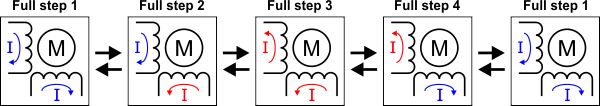 |
Allowed coil current transitions in full step mode. Arrows to the right correspond to one motor rotation direction and arrows to the left correspond to the other. |
|---|
Another way to visualize this is with a graph of the coil currents for each of the four full steps, with one axis representing the phase (or coil) A current and the other axis representing the phase B current. For “Full step” mode, where each coil always has approximately 70% of the configured current limit, that graph looks like this:
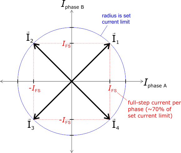 |
Coil currents for the four (4) steps that make up full-step mode (I1-4). |
|---|
In the other available step modes, the Tic uses microsteps instead of full steps to generate magnetic fields that point to places between the full steps. Each microstep corresponds to 1/2, 1/4, 1/8, 1/16, 1/32, 1/64, 1/128, or 1/256 of a full step, depending on what step mode you choose. For example, if you choose 1/32, then it will take 32 microsteps to move the same distance as one full step, and a motor with 200 steps per revolution will require 6400 microsteps to turn 360 degrees. The following graph shows the coil currents for each of the microsteps in 1/4-step mode:
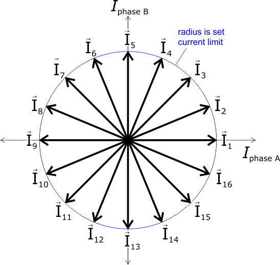 |
Coil currents for the 16 microsteps that make up 1/4-step mode (I1-16). |
|---|
In the above graph, currents I3, I7, I11, and I15 match the four full-step currents, where the magnitude of the current through both coils is equal. All other steps point between these full steps by setting different current limits for the two coils. The most extreme example of this occurs on steps I1, I5, I9, and I13, where the current through one coil is equal to the full current limit setting on the Tic while the current through the other coil is zero.
- The Tic T500 only supports full, 1/2, 1/4, and 1/8 step modes.
- The Tic T825 Tic T834, and Tic T249 support full, 1/2, 1/4, 1/8, 1/16, and 1/32 step modes.
- The Tic T249 supports “Full step 100%” mode instead of normal full step mode, and it additionally supports “1/2 step 100%” mode. In these two “100%” modes, any non-zero coil current is 100% of the rated current instead of 70% (as in the normal full and 1/2 step modes). These modes are sometimes described as “non-circular”.
- The Tic 36v4 supports full, 1/2, 1/4, 1/8, 1/16, 1/32, 1/64, 1/128, and 1/256 step modes.
The Tic’s speed, velocity, acceleration, and deceleration numbers are all denominated in microsteps, which are also called pulses. Therefore, if you change the step mode, you might have to change those other settings to account for the change. For example, the default maximum speed for the Tic is 200 pulses per second. If you change the step mode from full step to half step, you would have to change the speed to 400 pulses per second to maintain the same angular rate of change. Since the step mode affects those other parameters, it is a good idea to set it first.
Setting the decay mode (T825, T834, and 36v4 only)
The Tic T825, Tic T834, and Tic 36v4 have a decay mode setting that affects how fast current through the motor coils decays during each step.
- The Tic T825 has three decay modes: slow, mixed (default), and fast.
- The Tic T834 has five decay modes: slow, mixed 25%, mixed 50% (default), mixed 75%, and fast.
- The Tic 36v4 has six decay modes: slow, slow / mixed, fast, mixed, slow / auto-mixed, and auto-mixed (default).
The decay mode matters most when microstepping is used. Which decay mode is most appropriate depends on many factors specific to a particular stepper motor system, including the motor’s resistance and inductance, the supplied motor voltage, and the desired speed. Generally, using slow decay generates less electrical and audible noise, but it can result in missed microsteps when the coil current is decreasing. Fast decay is much noisier both electrically and audibly, but it creates more evenly sized microsteps. Mixed decay is a combination of both fast and slow decay that tries to minimize noise while keeping microsteps as even as possible. For more information about the decay modes and current control methods of the Tic’s stepper motor driver, refer to the DRV8825 datasheet (1k redirect) for the Tic T825 or the DRV8834 datasheet (1k redirect) for the Tic T834.
The Tic 36v4 is configured to use auto-mixed decay by default. In this mode, the driver automatically selects slow or fast decay based on the actual motor current. This combines some of the advantages of both slow and fast decay, and it should work well in most situations, but you can select a different decay mode if auto-mixed is not optimal for your system. Decay modes with a slash (/) indicate different behavior for increasing- and decreasing-current steps; for example, the “Slow / mixed” setting uses slow decay for steps where the current increases and mixed decay where the current decreases. For more information about the Tic 36v4’s decay modes, as well as the additional timing parameter settings that can affect their operation, refer to its DRV8711 gate driver IC’s datasheet (1k redirect) and to Section 6.
The decay mode of the Tic T500 is not configurable. The Tic T500 features automatic decay mode selection, using internal current sensing to automatically adjust the decay mode as necessary to provide the smoothest current waveform. For more information, see the MP6500 datasheet (1MB pdf).
The decay mode of the Tic T249 is not configurable. The Tic T249 features Toshiba’s Advanced Dynamic Mixed Decay (ADMD) technology, which dynamically switches between slow and fast decay modes based on the actual motor current, providing higher efficiency and smoother steps at high speed than you get with traditional timing-based mixed decay. For more information, see the TB67S249FTG datasheet (533k pdf).
Configuring Active Gain Control (T249 only)
The TB67S249FTG IC on the Tic T249 supports Toshiba’s Active Gain Control (AGC) feature, which automatically reduces the stepper motor current below the set limit based on the actual load on the motor, allowing for reduced unnecessary heat generation and higher peak power when the motor actually needs it. The AGC feature is disabled by default, but you can enable it and configure it using the AGC settings in the “Input and motor settings” tab. For more information about these settings, see Section 6.
Setting the movement parameters
After you have set the motor’s step mode, current limit, decay mode, and AGC settings (if applicable), you should set its maximum speed and maximum acceleration.
The Tic represents speeds (non-negative values indicating the magnitude of a velocity), velocities (signed values indicating speed and direction), and speed limits in units of pulses (microsteps) per 10,000 (ten thousand) seconds. The Tic can send up to 50,000 pulses (microsteps) per second, so the maximum allowed speed setting is 500,000,000. However, your motor might not be capable of moving that fast. If you want to get the maximum speed possible out of your motor, you might have to do some tests to see how fast it can go. To do this, set the max speed to 500,000,000 in the “Input and motor settings” and click “Apply settings”. Then go to the “Set target” box in the “Status” tab, select “Set velocity”, and enter smaller numbers in the boxes at the ends of the scroll bar that determine its range. For example, try entering -4,000,000 and 4,000,000, which would mean the scrollbar can set target velocities between −400 pulses per second and +400 pulses per second, as shown below.
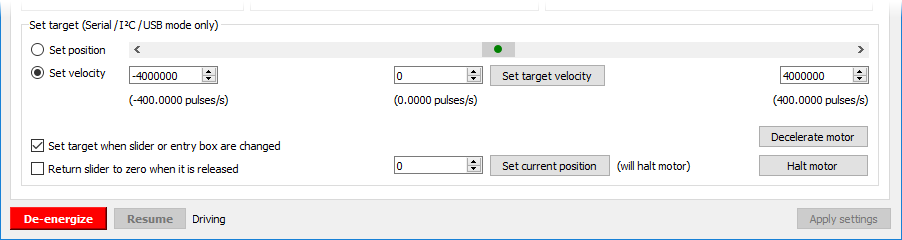 |
The “Set target” box in the Tic Control Center, with its range set to plus or minus 400 pulses per second. |
|---|
Try slowly dragging the scrollbar to both ends of its range. If your motor is able to reach the desired speeds without pausing or skipping, you can increase the range of the scrollbar and try again. By experimenting with the velocity scrollbar, you should be able to get an idea of what your motor can do. Once you have done that, go back to the “Input and motor settings” tab and set the “Max speed” appropriately.
You will probably have to adjust the “Max acceleration” parameter too. The Tic represents acceleration and deceleration limits in units of pulses per second per 100 seconds. The acceleration and deceleration limits specify how much the speed (in units of 10,000 pulses per second) is allowed to rise or fall in one hundredth of a second (0.01 s or 10 ms). To set the acceleration limit, you might consider how much time you want the Tic to spend accelerating from rest to full speed. If you want it to take one second, then set the maximum acceleration to be one hundredth of the maximum speed.
Unlike a DC motor, which will accelerate on its own up to some max speed when a voltage is applied, step rates must be gradually increased by the controller if you want to achieve high maximum speeds. If you just jump abruptly to a high step rate, the inertia of the stationary rotor will prevent it from being able to keep up with the rotating magnetic field and it will get left behind; the result of this is that it will just sit there or vibrate in place (or possibly even start moving backward). The Tic’s max acceleration parameter limits how quickly the step rates will increase, which if set correctly, will give the rotor time to keep up with the magnetic field as it spins faster and faster (up to some maximum speed that is ultimately a function of your specific stepper motor as well as the current limit setting, the supply voltage, and the load on the stepper motor output).
By default, the Tic’s deceleration limit is the same as its acceleration limit. If you want the deceleration rate to be different, you can uncheck the “Use max acceleration limit for deceleration” box.
The “Starting speed” parameter specifies a speed below which deceleration and acceleration limits are not respected. For example, if you set the starting speed to 1000000 (100 pulses per second), then the Tic will be able to instantly change from any velocity in the range of −1000000 to +1000000 to any other velocity in that range. Setting the starting speed might allow you to make your system faster since it will not waste time accelerating or decelerating through low speeds where it is not needed.
Related products


Related categories


Home | Forum | Blog | Support | Ordering Information | Lists | Distributors | BIG Order Form | About | Contact
© 2001–2026 Pololu Corporation
