Support » Tic Stepper Motor Controller User’s Guide » 4. Setting up the controller »
4.1. Choosing the power supply, Tic, and stepper motor
The information in this section can help you select a power supply, a Tic controller, and a stepper motor that will work well together.
Stepper motor configurations
There are different types of stepper motors. The Tic is designed to work with two-phase stepper motors that can be connected in a bipolar configuration. The following diagram shows examples of such stepper motors:
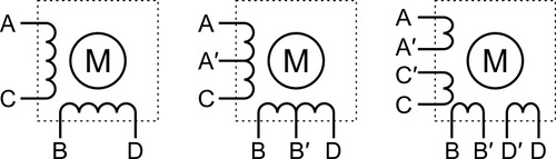 |
The Tic works with two-phase stepper motors that can be controlled in a bipolar configuration. |
|---|
Your stepper motor should have one of the configurations shown above, or else it might not work with the Tic. The next section explains how to connect these stepper motors to your Tic.
Voltage and current ratings
When selecting your power supply, Tic controller, and stepper motor, you must consider the voltage and current ratings of each.
The voltage range of your power supply is the range of voltages you expect your power supply to produce while operating. There is usually some variation in the output voltage so you should treat it as a range instead of just a single number. In particular, keep in mind that a fully-charged battery might have a voltage that is significantly higher than its nominal voltage.
The current limit of a power supply is how much current the power supply can provide. Note that the power supply will not force this amount of current through your system; the properties of the system and the voltage of the power supply determine how much current will flow, but there is a limit to how much current the power supply can provide.
The operating voltage range of a Tic is the range of voltages from which it can be powered. The operating voltages of the different Tic controllers are shown in the table below. The Tic requires a DC power supply.
The continuous current per phase of a Tic is the maximum amount of current that the Tic can continuously provide to each phase of the stepper motor. The continuous current per phase of the different Tic controllers are shown in the table below.
| Tic T500 | Tic T834 | Tic T825 | Tic T249 | Tic 36v4 | |
|---|---|---|---|---|---|
| Operating voltage range: | 4.5 V to 35 V | 2.5 V to 10.8 V | 8.5 V to 45 V | 10 V to 47 V | 8 V to 50 V |
| Continuous current per phase: | 1.5 A | 1.5 A | 1.5 A | 1.8 A | 4 A |
Note: While the Tic T500 can operate down to 4.5 V, power supply voltages under 5.5 V could cause a drop in the logic voltage of the board, potentially down to around 4 V when the power supply is 4.5 V. This logic voltage drop causes the Tic’s VIN voltage measurements to become inaccurate (too high). If you are connecting analog voltages powered from an external source to the Tic, the lower logic voltage will cause the Tic’s analog readings to rise and possibly require recalibration. The logic voltage drop should not affect a potentiometer that is connected to the Tic in the standard way using the GND, SDA/AN, and SCL pins, since the voltage on the potentiometer output will drop by the same percentage as the Tic’s logic voltage.
The rated current of a stepper motor is the maximum amount of current that the stepper motor was designed to have flowing through each phase, and this is typically the current required to achieve the stepper motor’s published performance specifications.
The rated voltage of a stepper motor is how much voltage needs to be applied to a coil of the stepper motor to get the rated current to flow through it. Ohm’s law provides the simple relationship between the rated voltage and the rated current: the rated voltage is equal to the rated current multiplied by the coil resistance.
These are the main constraints you should keep in mind when selecting your power supply, Tic controller, and stepper motor:
- The voltage of your power supply should be greater than or equal to the rated voltage of your stepper motor. Otherwise, the motor will not receive its full rated current and you will not get the full performance that the motor is capable of. It is OK for the power supply voltage to be higher than the rated voltage of the motor because the Tic has active current limiting. (It rapidly switches the power to the motor on and off while measuring the current to make sure it does not go too high.)
- A higher power supply voltage is usually desirable since it allows higher speed and torque. However, if the power supply voltage is extremely high compared to the stepper motor’s rated voltage and you want to use microstepping, you might experience skipped steps.
- The voltage of your power supply should be within the operating voltage range of the Tic. Otherwise, the Tic could malfunction or (in the case of high voltages) be damaged.
- The continuous current per phase of the Tic should be greater than or equal to the rated current of the stepper motor. Otherwise, the Tic will not be able to deliver the full rated current to the motor and you will not get the full performance that your motor is capable of. (However, if you are using USB, serial, or I²C to control the Tic, you might be able to get better performance out of the Tic by dynamically increasing the current limit above the Tic’s continuous current rating whenever you move the motor, and reducing it while the motor is holding position, thus maintaining a low average current.) If the motor’s rated current is substantially more than the Tic’s current, then it is possible that the Tic will not be able to move the motor at all.
- We generally recommend you choose a power supply with a current limit that is at least at least twice the current limit you are planning to use on the Tic as that amount of current should always be safely beyond what the Tic will draw. The current limit you configure on the Tic should generally not exceed the stepper motor’s rated current and should not exceed the continuous current per phase of the Tic. So if you take the smaller of those two currents, and then multiply that current by two, and get a power supply that can provide at least the much current, you can be sure that the power supply’s current will not be the limiting factor in your application. However, please note that you can typically get by with less power supply current than this, especially if your supply voltage is higher than the rated voltage of your stepper motor. In this situation, the Tic’s current control acts as a step-down converter, meaning that a small amount of current from the power supply at a higher voltage can generate a larger amount of current going through the coils at a lower voltage. Also, most Tic controllers never actually drive both coils at the configured current limit at the same time. The total current going through the coils is maximized in the four full-step positions, where the Tic will be sending 71% of the current limit through each coil, for a total current of 142% of the current limit. (The Tic T249 is the only exception; it has two step modes where it will send the full configured current into both coils at the same time.) If you want to know the maximum current draw from your power supply, you can measure this with a multimeter while the stepper motor is energized in full-step mode and not stepping. If your system draws too much current, your power supply might shut down, overheat, produce a lower voltage, and/or be damaged.
It is worth noting again that since the Tic actively limits current through the motor coils, you can safely use power supplies with voltages above the rated voltage of the stepper motor as long as you set the current limit to not exceed the stepper motor’s rated current. For example, this means that the Tic T825 (which has a minimum operating voltage of 8.5 V) can be used with a stepper motor rated for 3.2 V if the current limit is set appropriately.
Related products


Related categories


Home | Forum | Blog | Support | Ordering Information | Lists | Distributors | BIG Order Form | About | Contact
© 2001–2026 Pololu Corporation
