Support » Tic Stepper Motor Controller User’s Guide » 4. Setting up the controller »
4.6. Setting up I²C control
This section explains how to connect a microcontroller to the Tic’s I²C interface so that you can send commands to control the Tic. The Tic Stepper Motor Controller library for Arduino makes it particularly easy to control the Tic from an Arduino or Arduino-compatible board such as an A-Star 32U4.
About the I²C interface
The SCL and SDA/AN pins of the Tic provide its I²C interface. The pins are open drain outputs, meaning that they only drive low and they never drive high. Each pin has a 220 Ω or 470 Ω series resistor protecting it from short circuits. By default, each pin is pulled up to 5 V by the Tic’s microcontroller with a pull-up resistor that is typically around 40 kΩ. When the Tic is reading the SCL or SDA pin as an input, any value over 2.1 V will be considered to be high.
Devices on the I²C bus have two roles: a master that initiates communication, and a slave that responds to requests from a master. The Tic acts as the slave. The Tic uses a feature of I²C called clock stretching, meaning that it holds the SCL line low to delay I²C communication while it is busy processing data from the master.
Connecting an I²C device to one Tic
If you have not done so already, you should follow the instructions in Section 4.3 to configure and test your stepper motor. You should leave your Tic’s control mode set to its default value of “Serial / I²C / USB” and leave the “Device number” set to its default value of 14. The “Device number” specifies the 7-bit address for the Tic to use on the I²C bus.
Next, connect your device’s SCL pin to the Tic’s SCL pin, and connect your device’s SDA pin to the Tic’s SDA pin. You should also connect your device’s GND (ground) pin to one of the Tic’s GND pins. These connections, and some other optional connections, are shown in the diagram below:
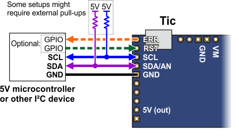 |
Because the Tic considers an input value of 2.1 V on SCL or SDA to be high, you can connect those pins directly to 3.3 V microcontrollers without needing a level shifter. If your microcontroller’s I²C interface is not 5V tolerant, it will usually still have a diode going from each I/O pin to its logic supply. These diodes clamp the voltage on the pins, preventing the Tic’s pull-up resistors from pulling the pins too high. If you want to be extra safe and not rely on the clamping diodes, you can disable the Tic’s pull-up resistors by going to the “Advanced settings” tab in the Tic Control Center, changing the functions of SCL and SDA to “Serial”, and making sure the “Pull-up” checkbox for each pin is not checked.
Depending on your setup, you might need to add pull-up resistors to the SCL and SDA lines of your I²C bus to ensure that the signals rise fast enough. The Tic’s pull-up resistors are enabled by default, and many I²C master devices will have pull-ups too, but that might not be enough, especially if you want to use speeds faster than 100 kHz or have long wires. The I²C-bus specification and user manual (1MB pdf) has some information about picking pull-up resistors in the “Pull-up resistor sizing” section, and trying a value around 10 kΩ is generally a good starting point.
If you are using an Arduino or Arduino-compatible board, you should now try running the I2CSpeedControl example that comes with the Tic Arduino library. If you are using a different kind of microcontroller board, you will need to find or write code to control the Tic on your platform. If you are writing your own code, we recommend that you first learn how to use the I²C interface of your platform, and then use the I2CSpeedControl example as a reference. You should also refer to the sections in this guide about the Tic’s commands (Section 8) and I²C protocol (Section 10).
If your connections and code are OK, you should now see the Tic’s stepper motor moving back and forth. If the stepper motor is not moving, you should check all of your connections and solder joints (if applicable). You should check the “Status” tab of the Tic Control Center to see if any errors are being reported. You can also try slowing down your I²C clock speed to something very slow like 1 kHz or 10 kHz. If slowing down the clock works, then the problem might be due to not having strong enough pull-up resistors on the SDA and SCL lines.
Optional connections
The Tic’s 5V (out) pin provides access to the output of the Tic’s 5V regulator, which also powers the Tic’s microcontroller and the red and yellow LEDs. You can use the Tic’s regulator to power your microcontroller or another device if the device does not draw too much current (see Section 5.8).
The VM pin provides access to the Tic’s power supply after the reverse-voltage protection circuit, and this pin can be used to provide reverse-voltage-protected power to other components in the system if the Tic supply voltage is within the operating range of those components. Note: this pin should not be used to supply more than 500 mA; higher-current connections should be made directly to the power supply. Unlike the 5V (out) pin described above, this is not a regulated, logic-level output.
The ERR pin of the Tic is normally pulled low, but drives high to indicate when an error is stopping the motor. You can connect this line to an input on your microcontroller (assuming it is 5V tolerant) to quickly tell whether the Tic is experiencing an error or not. Alternatively, you can query the Tic’s serial interface to see if an error is happening, and which specific errors are happening. For more information about the ERR pin, see Section 5.4.
The RST pin of the Tic is connected directly to the reset pin of the Tic’s microcontroller and also has a 10 kΩ resistor pulling it up to 5 V. You can drive this pin low to perform a hard reset of the Tic’s microcontroller and de-energize the stepper motor, but this should generally not be necessary for typical applications. You should wait at least 10 ms after a reset to transmit to the Tic.
Controlling multiple Tics with I²C
I²C is designed so that you can control multiple slave devices on a single bus. Before attempting to do this, however, we recommend that you first get your system working with just one Tic as described above.
Next, make sure that the I²C master device and the Tics all share a common ground, for example by connecting a GND pin from the I²C master device to a GND pin on each of the Tics. Make sure that the SCL pins of all devices are connected and that the SDA pins of all devices are connected.
You should use the Tic Control Center to configure each Tic to have a different “Device number”, which specifies the 7-bit I²C address to use. Then you should change your code to use those addresses. If you are using our Tic Arduino library, you can declare one object for each Tic by writing code like this at the top of your sketch, which uses addresses 14 and 15:
TicI2C tic1(14);
TicI2C tic2(15);
The following diagram shows the standard I²C connections described above along with optional connections of the ERR and RST pins:
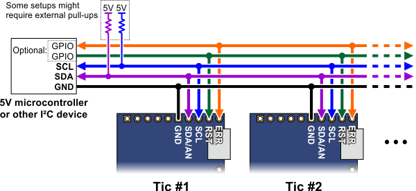 |
The ERR pins can all be safely connected together. In such a configuration, the line will be high if one or more Tics has an error; otherwise, it will be low. Additionally, the Tics are configured by default to treat a high signal on their ERR lines as an error, so an error on one Tic will trigger an error on all other Tics when their ERR lines are connected as shown in the above diagram. This behavior can be disabled by checking the “Ignore ERR line high” box under the “Advanced settings” tab of the Tic Control Center. For more information on the ERR pin and error handling in general, see Section 5.4.
More information about the I²C interface
This user’s guide has more information about the Tic’s commands (Section 8) and I²C protocol (Section 10).
Related products


Related categories


Home | Forum | Blog | Support | Ordering Information | Lists | Distributors | BIG Order Form | About | Contact
© 2001–2026 Pololu Corporation
