Support » Tic Stepper Motor Controller User’s Guide » 4. Setting up the controller »
4.5. Setting up serial control
This section explains what kind of serial interface the Tic has and how to connect a microcontroller or other TTL serial device to it so that you can send commands to control the Tic. The Tic Stepper Motor Controller library for Arduino makes it particularly easy to control the Tic from an Arduino or Arduino-compatible board such as an A-Star 32U4.
About the serial interface
The RX and TX pins of the Tic provide its serial interface. The Tic’s RX pin is an input, and its TX pin is an output. Each pin has an integrated 100 kΩ resistor pulling it up to 5 V and a 220 Ω or 470 Ω series resistor protecting it from short circuits.
The serial interface uses non-inverted TTL logic levels: a level of 0 V corresponds to a value of 0, and a level of 5 V corresponds to a value of 1. The input signal on the RX pin must reach at least 4 V to be guaranteed to be read as high, but 3.3 V signals on RX typically work anyway.
The serial interface is asynchronous, meaning that the sender and receiver each independently time the serial bits. The sender and receiver must be configured to use the same baud rate, which is typically expressed in units of bits per second. The data format is 8 data bits, one stop bit, with no parity, which is often expressed as 8-N-1. The diagram below depicts a typical serial byte:
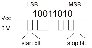 |
Diagram of a non-inverted TTL serial byte. |
|---|
The serial lines are high by default. The beginning of a transmitted byte is signaled with a single low start bit, followed by the bits of byte, least-significant bit (LSB) first. The byte is terminated by a stop bit, which is the line going high for at least one bit time.
Connecting a serial device to one Tic
If you have not done so already, you should follow the instructions in Section 4.3 to configure and test your stepper motor. You should leave your Tic’s control mode set to “Serial / I²C / USB” (the default), and you should also set your desired baud rate.
Next, connect your serial device’s GND (ground) pin to one of the Tic’s GND pins.
If your serial device operates at 5 V, you can directly connect the device’s TX line to the Tic’s RX line and connect the Tic’s TX line to the device’s RX line. The connection to the Tic’s TX line is only needed if you want to read data back from the Tic. These connections, and some other optional connections, are shown in the diagram below:
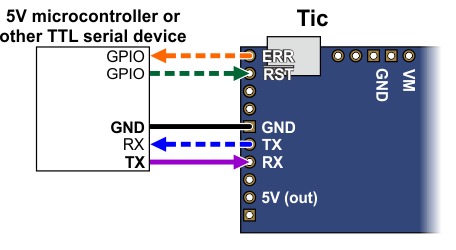 |
If your serial device operates at 3.3 V, then you might need additional circuitry to shift the voltage levels. You can try connecting the device’s TX line directly to the Tic’s RX line; this will usually work, but the input signal on the RX pin must reach at least 4 V to be guaranteed to be read as high. If you want to read data from the Tic, you will need to consider how to connect the Tic’s TX line to your device’s RX line. If your device’s RX line is 5V tolerant, meaning that it can accept a 5 V output being applied directly to it, then you should be able to connect the Tic’s TX line directly to your device’s RX line. If your device’s RX line is not 5V tolerant, you will need to a use a level shifter—a separate board or chip that can convert 5 V signals down to 3.3 V. A voltage divider made with two resistors would work too.
Whenever connecting devices, remember to wire the grounds together, and ensure that each device is properly powered. Unpowered devices with a TTL serial port can turn on or partially on, drawing power from the serial line, which means that extra care must be taken when turning power off and on to reset the devices.
Note: You must use an inverter and level shifter such as a MAX232 or a Pololu 23201a Serial Adapter if you want to interface an RS-232 device with the Tic. Connecting an RS-232 device directly to the Tic can permanently damage it.
If you are using an Arduino or Arduino-compatible board, you should now try running the SerialSpeedControl example that comes with the Tic Arduino library. The library’s README has information about how to get started and which pins of the Arduino to use. If you are using a different kind of microcontroller board, you will need to find or write code to control the Tic on your platform. If you are writing your own code, we recommend that you first learn how to send and receive serial bytes on your platform, and then use the SerialSpeedControl example as a reference. You should also refer to the sections in this guide about the Tic’s commands (Section 8) and serial protocol (Section 9).
If your connections and code are OK, you should now see the Tic’s stepper motor moving back and forth. If the stepper motor is not moving, you should check all of your connections and solder joints (if applicable). You should make sure that the Tic and your device are configured to use the same baud rate. The Tic uses 9600 bits per second by default. You should also check the “Status” tab of the Tic Control Center to see if any errors are being reported.
The SerialSpeedControl example only writes data to the Tic, so it does not test your connection to the Tic’s TX line. If you want to read data from the Tic, you should now try the SerialPositionControl example, which reads the current position of the stepper motor from the Tic.
Optional connections
The Tic’s 5V (out) pin provides access to the output of the Tic’s 5V regulator, which also powers the Tic’s microcontroller and the red and yellow LEDs. You can use the Tic’s regulator to power your microcontroller or other serial device if the device does not draw too much current (see Section 5.8).
The VM pin provides access to the Tic’s power supply after the reverse-voltage protection circuit, and this pin can be used to provide reverse-voltage-protected power to other components in the system if the Tic supply voltage is within the operating range of those components. Note: this pin should not be used to supply more than 500 mA; higher-current connections should be made directly to the power supply. Unlike the 5V (out) pin described above, this is not a regulated, logic-level output.
The ERR pin of the Tic is normally pulled low, but drives high to indicate when an error is stopping the motor. You can connect this line to an input on your microcontroller (assuming it is 5V tolerant) to quickly tell whether the Tic is experiencing an error or not. Alternatively, you can query the Tic’s serial interface to see if an error is happening, and which specific errors are happening. For more information about the ERR pin, see Section 5.4.
The RST pin of the Tic is connected directly to the reset pin of the Tic’s microcontroller and also has a 10 kΩ resistor pulling it up to 5 V. You can drive this pin low to perform a hard reset of the Tic’s microcontroller and de-energize the stepper motor, but this should generally not be necessary for typical applications. You should wait at least 10 ms after a reset to transmit to the Tic.
Connecting a serial device to multiple Tics
The Tic’s serial protocol is designed so that you can control multiple Tics using a single TTL serial port. Before attempting to do this, however, we recommend that you first get your system working with just one Tic as described above.
Next, make sure that the serial device and the Tics all share a common ground, for example by connecting a GND pin from the device to a GND pin on each of the Tics. Make sure that the TX pin on the serial device is connected to the RX pin of each Tic (via a level shifter if needed).
If you attempt to run the SerialSpeedControl example in this configuration, you should see each of your Tic controllers moving their stepper motors in unison. That example uses the Tic’s Compact Protocol, which is only suitable for controlling one device. The Compact Protocol commands do not contain a device number, so every Tic device that sees a Compact Protocol command will obey it. This is probably not what you want.
To allow independent control of multiple Tics, you should use the Tic Control Center to configure each Tic to have a different device number. Then you should change your code to use the Pololu Protocol as described in Section 9. If you are using our Tic Arduino library, you can declare one object for each Tic, and specify the device number of each Tic, by writing code like this at the top of your sketch, which uses device numbers 14 and 15:
TicSerial tic1(ticSerial, 14);
TicSerial tic2(ticSerial, 15);
If you want to read data from multiple Tics, you cannot simply connect all of the Tic TX lines together, because when one of Tics tries to drive its TX line low to send data, the TX lines from the other Tics will still be driving the line high and will prevent the signal from going all the way to 0 V. Instead, you will need to connect an external AND gate. The TX line of each Tic should be connected to an input line of the AND gate. The output of the AND gate should be connected to the RX line of your serial device (through a voltage divider or level shifter if necessary). The following diagram shows these connections along with optional connections of the ERR and RST pins:
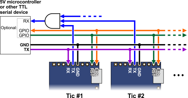 |
The ERR pins can all be safely connected together. In such a configuration, the line will be high if one or more Tics has an error; otherwise, it will be low. Additionally, the Tics are configured by default to treat a high signal on their ERR lines as an error, so an error on one Tic will trigger an error on all other Tics when their ERR lines are connected as shown in the above diagram. This behavior can be disabled by checking the “Ignore ERR line high” box under the “Advanced settings” tab of the Tic Control Center. For more information on the ERR pin and error handling in general, see Section 5.4.
Using I²C instead of serial to read data from multiple Tics does not require an AND gate (see Section 4.6).
More information about the serial interface
This user’s guide has more information about the Tic’s commands (Section 8) and serial protocol (Section 9).
Related products


Related categories


Home | Forum | Blog | Support | Ordering Information | Lists | Distributors | BIG Order Form | About | Contact
© 2001–2026 Pololu Corporation
