Support » Tic Stepper Motor Controller User’s Guide »
9. Serial command encoding
As described in Section 8, the Tic’s serial commands each use one of four formats: quick, 7-bit write, 32-bit write, and block read. This section explains how these four command formats are encoded as sequences of bytes within TTL serial command packets.
The following examples are shown using the compact protocol, which is intended for cases where the Tic is the only device connected to your serial line. Later on, this section also describes the Pololu protocol, which can be used to daisy-chain a Tic on a single serial line with other devices (including additional Tics).
For a reference implementation of these protocols, see the TicSerial class in our Tic Stepper Motor Controller library for Arduino.
Quick
| command |
A quick command sends no data and simply consists of the command byte.
Example: Halt and hold
| command |
| 0x89 |
7-bit write
| command | data |
A 7-bit write command has a single byte of data containing a 7-bit value (the most-significant bit of the data byte is always 0) that comes after the command byte.
Example: Set step mode to 1/8 step
| command | data |
| 0x94 | 0x03 |
32-bit write
| command | MSbs | data 1 | data 2 | data 3 | data 4 |
A 32-bit write command has five data bytes encoding a 32-bit value. Bits 0 through 3 of the first byte contain the most-significant bits (MSbs) for the four data bytes that follow: bit 0 is the MSb for the least-significant data byte and bit 3 is the MSb for the most-significant data byte. The last four data bytes contain the 32-bit value in little-endian order (starting with the least-significant byte), but with the most-significant bit of each byte cleared.
Example: Set target position to 1,234,567,890
| command | MSbs | data 1 | data 2 | data 3 | data 4 |
| 0xE0 | 0x05 | 0x52 | 0x02 | 0x16 | 0x49 |
Write value: 1,234,567,890 = 0100 1001 1001 0110 0000 0010 1101 0010
- MSbs: 0000 0101 = 0x05
- data 1: 0101 0010 = 0x52
- data 2: 0000 0010 = 0x02
- data 3: 0001 0110 = 0x16
- data 4: 0100 1001 = 0x49
Block read
| command | offset | length | → | data 1 | … | data length |
A block read command reads a block of data from the Tic. The offset byte specifies the offset within the data that the response should start at, and the length byte specifies how many bytes of data the response should include. The length must be between 1 and 15. Any multi-byte values contained in the response are in little-endian order (starting with the least-significant byte).
Example: Get variable “target position” (32 bits)
| command | offset | length | → | data 1 | data 2 | data 3 | data 4 |
| 0xA1 | 0x0A | 0x04 | 0xD2 | 0x02 | 0x96 | 0x49 |
Read value: 0x4996 02D2 = 1,234,567,890
Starting with firmware version 1.07, you can set bit 6 of the length byte in order to add 128 to the offset without affecting the length. This allows you to access offsets between 128 and 255, which were previously inaccessible because the offset byte—like any data byte—must be between 0 and 127. In other words, bit 6 of the length byte is now treated as bit 7 of the desired offset, instead of bit 6 of the desired length.
Serial protocols
Like many other Pololu products, the Tic supports two different serial command protocols.
The compact protocol is the simpler of the two protocols; it is the protocol you should use if your Tic is the only device connected to your serial line. The compact protocol command packet is simply a command byte followed by any data bytes that the command requires. All of the examples above use the compact protocol; here is the example for the Set step mode command again (selecting 1/8 step mode):
| command | data |
| 0x94 | 0x03 |
Notice that a command byte always has its most significant bit set (it is in the range 0x80 to 0xFF), while a data byte sent to the Tic always has its most significant bit cleared (it is in the range 0x00 to 0x7F); this is why a 32-bit write command requires five bytes to represent a 32-bit number. Responses from the Tic can contain data bytes of any value from 0x00 to 0xFF.
The Pololu protocol can be used in situations where you have multiple devices connected to your serial line. This protocol is compatible with the serial protocol used by our other serial motor and servo controllers. As such, you can daisy-chain a Tic on a single serial line along with our other serial controllers (including additional Tics) and, using this protocol, send commands specifically to the desired Tic without confusing the other devices on the line.
To use the Pololu protocol, you must transmit 0xAA (170 in decimal) as the first (command) byte, followed by a device number data byte. The default device number for the Tic is 0x0E (14 in decimal), but this is a setting you can change. (The device number is also used as the Tic’s I²C slave address.) Any controller on the line whose device number matches the specified device number accepts the command that follows; all other Pololu devices ignore the command. The remaining bytes in the command packet are the same as the compact protocol command packet you would send, with one key difference: the compact protocol command byte is now a data byte for the command 0xAA and hence must have its most significant bit cleared. Therefore, the same “set step mode” command from above, but using the Pololu protocol, looks like this:
| device # | command | data | |
| 0xAA | 0x0E | 0x14 | 0x03 |
The byte 0x14 is the “Set step mode” command (0x94) with its most significant bit cleared.
The Tic can be configured to respond to an alternative device number. If the alternative device number is enabled, the Tic will respond to commands that are addressed it, in addition to commands addressed to the regular device number. This can be useful if you want to assign your Tics to groups and send a single command to all the Tics in the group, while still being able to individually address each Tic. You can enable the alternative device number by checking the checkbox labeled “Alternative device number” in the “Input and motor settings” tab and then entering the number in the corresponding numeric input. This feature was added in firmware version 1.06.
The Tic can be configured to use 14-bit device numbers. With this option enabled, the device numbers can range from 0 to 16383, instead of the typical range of 0 to 127. After the 0xAA byte, you have to send two device number bytes, both of which are between 0 and 127: the first byte holds the lower 7 bits of the device number, while the second byte holds the upper 7 bits of the device number. You can enable 14-bit device numbers by checking the checkbox labeled “Enable 14-bit device number” in the “Input and motor settings” tab. This feature is useful if you want your system to have more than 128 devices. This feature was added in firmware version 1.06.
The TicSerial class in our Tic Arduino library uses the compact protocol by default if the optional deviceNumber argument is omitted, but you can make it use the Pololu protocol instead by providing a device number. See the library documentation for more details.
The diagram below shows how to connect multiple devices that support the Pololu protocol and control them from the serial interface of a single 5V microcontroller or other serial device. The AND gate is only needed if you want to read data back from more than one device.
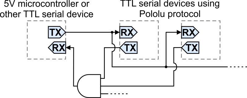 |
Daisy-chaining multiple TTL serial devices that support the Pololu protocol for control by a single microcontroller. |
|---|
Cyclic Redundancy Check (CRC) error detection
For certain applications, verifying the integrity of the data you are sending and receiving can be very important. Because of this, the Tic has optional 7-bit cyclic redundancy checking (CRC). Given a series of bytes, the Tic’s CRC algorithm generates a 7-bit number between 0 and 127 called the CRC byte, which is similar to a checksum but more robust as it can detect errors that would not affect a checksum, such as an extra zero byte or bytes out of order.
The Tic has two options for enabling CRC in the “Input and and motor settings” tab of the Tic Control Center.
The Enable CRC for commands option makes the Tic expect a CRC byte to be added onto the end of every command packet. The CRC byte is computed by applying the CRC algorithm described below to the other bytes of the command packet, including the 0xAA byte and the device number if you are using the Pololu Protocol. If the CRC byte is incorrect, a CRC error will occur and the command will be ignored.
The Enable CRC for responses option makes the Tic append a CRC byte onto the end of any response that it sends. The CRC byte is between 0 and 127, and is computed by applying the CRC algorithm described below to the other bytes of the response. You can check the CRC byte when processing the response from the Tic. The maximum response size supported by the Tic is 15 bytes, so it will not append a CRC byte onto responses that are already 15 bytes long. This behavior might change in future firmware versions. We recommend that you request at most 14 bytes of data when using this option, so that the CRC byte can always be appended. The “Enable CRC for responses” option was added in firmware version 1.06.
A detailed account of how cyclic redundancy checking works is beyond the scope of this document, but you can find more information using Wikipedia. The CRC computation is basically a carryless long division of a CRC “polynomial”, 0x91, into your message (expressed as a continuous stream of bits), where all you care about is the remainder. The Tic uses CRC-7, which means it uses an 8-bit polynomial and, as a result, produces a 7-bit remainder. This remainder is the lower 7 bits of the CRC byte that is tacked onto the end of a message.
The C code below shows one way to implement the CRC algorithm:
#include <stdint.h>

uint8_t getCRC(uint8_t * message, uint8_t length)
{
  uint8_t crc = 0;
  for (uint8_t i = 0; i < length; i++)
  {
    crc ^= message[i];
    for (uint8_t j = 0; j < 8; j++)
    {
      if (crc & 1) { crc ^= 0x91; }
      crc >>= 1;
    }
  }
  return crc;
}
Note that the innermost for loop in the example above can be replaced with a lookup from a precomputed 256-byte lookup table, which should be faster.
For example, a compact protocol “Set step mode” command selecting 1/8 step mode with a CRC byte appended to it would be:
| Compact protocol with CRC: | 0x94 | 0x03 | 0x10 |
7-bit responses
In general, the data sent by the Tic in response to serial commands is arbitrary binary data: the bytes can be anything from 0 to 255. The Tic’s “Enable 7-bit responses” option causes it to encode those responses in a format that only uses values from 0 to 127. This can be useful if you have wired your Tics in such a way that the responses from one Tic will be seen by another Tic, and you do not want those responses to accidentally be interpreted as commands. This feature was added in firmware version 1.06.
The 7-bit encoding performed by the Tic works as follows. First, if the serial response is longer than 7 bytes, the Tic truncates it to be exactly 7 bytes long, throwing away all the bytes after the first 7. This behavior might change in future firmware versions, so we recommend that you do not request more than 7 bytes from the Tic if you have enabled 7-bit responses. Next, the Tic sets the most-significant bit of each byte in the response to 0. The Tic packs the former values of those most significant bits (MSbs) into a single byte and appends it to the response. The bits of that final byte are in the same order as the bytes they correspond to: the least significant bit corresponds to the first byte, while the next bit corresponds to the second byte, and so on. The Tic does this conversion before it computes and appends the optional CRC byte.
Below is some C code you can use to undo the 7-bit encoding and restore the MSbs to their respective bytes. The length argument should be the length of the entire 7-bit response, including the final byte with the MSbs, but not including the CRC byte (if there is one). After this function runs, the byte holding the MSbs is redundant and can be ignored.
void undo7BitEncoding(uint8_t * message, uint8_t length)
{
  uint8_t msbs = message[length - 1];
  for (uint8_t i = 0; i < length - 1; i++)
  {
    if (msbs & 1) { message[i] |= 0x80; }
    msbs >>= 1;
  }
}
Related products


Related categories


Home | Forum | Blog | Support | Ordering Information | Lists | Distributors | BIG Order Form | About | Contact
© 2001–2026 Pololu Corporation
