Motion Control Modules » Stepper Motor Drivers » TB67S579FTG Stepper Motor Driver Carriers »
TB67S579FTG Stepper Motor Driver Carrier - Full Breakout
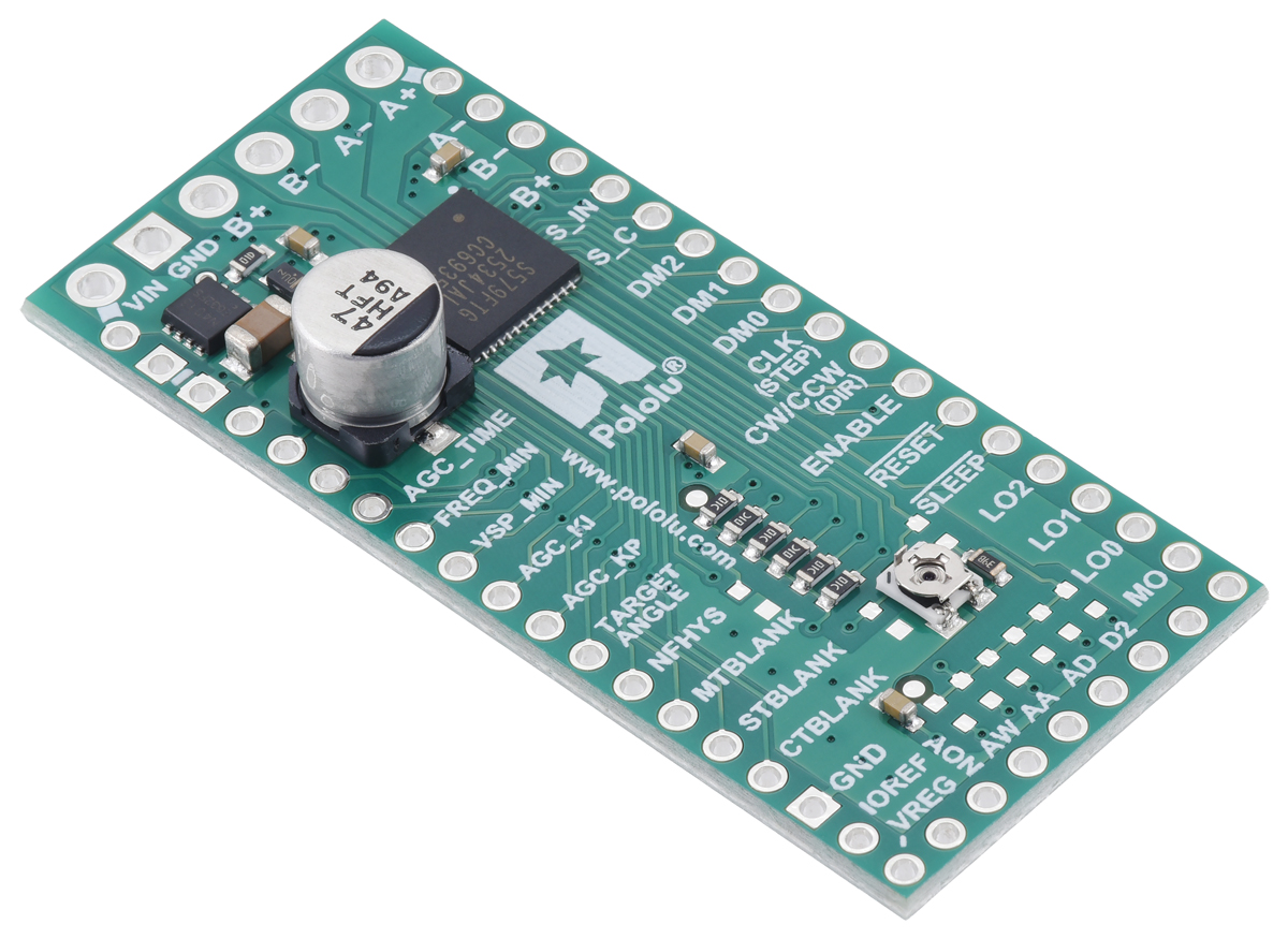
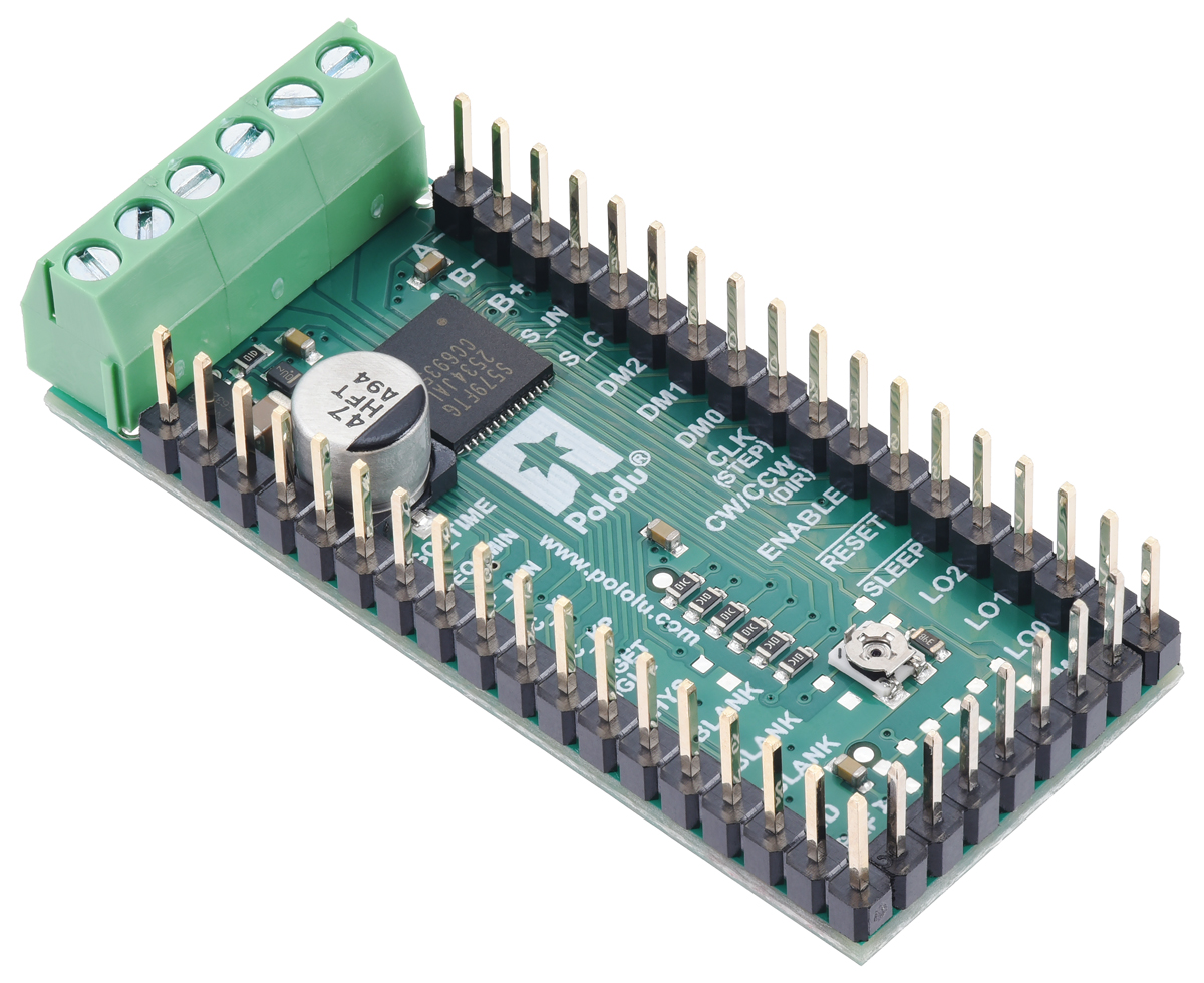
This breakout board for Toshiba’s TB67S579FTG microstepping bipolar stepper motor driver provides access to all of the driver’s pins, enabling use of its many features, including advanced dynamic mixed decay (ADMD), automatic gain control (AGC), and automatic wave generation system (AWGS). The TB67S579FTG has a wide operating voltage range of 4.5 V to 34 V, and our carrier board can deliver approximately 1.2 A per phase continuously without a heat sink or forced air flow (up to 2 A peak). It features built-in protection against over-current and over-temperature conditions.
 Compare all products in TB67S579FTG Stepper Motor Driver Carriers or 16-pin Stepper Motor Drivers.
| Description | Specs (15) | Pictures (12) | Resources (8) | FAQs (4) | On the blog (0) | Distributors (0) |
|---|
Overview
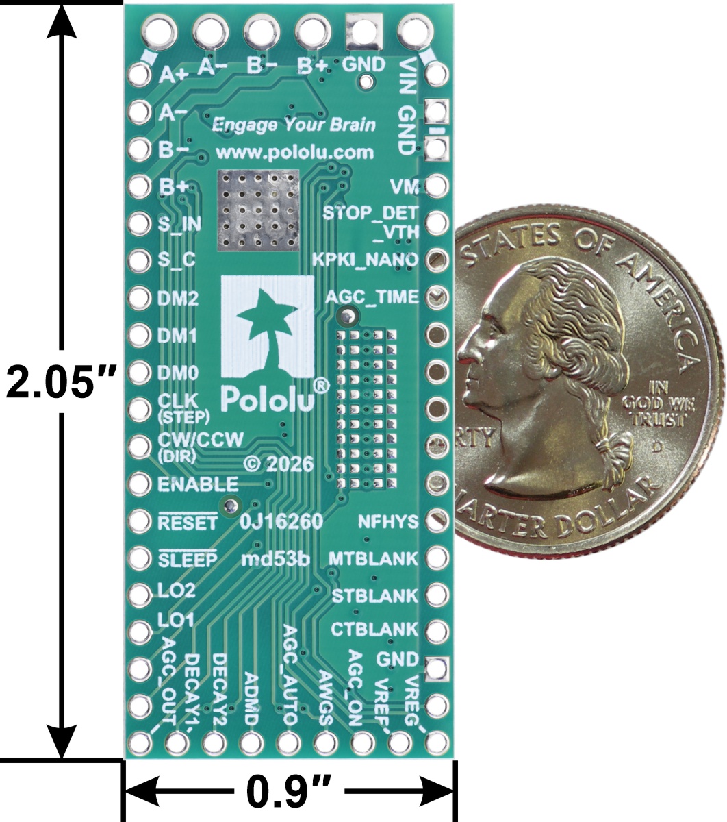 |
This product is a carrier board or breakout board for Toshiba’s TB67S579FTG bipolar stepper motor driver; we therefore recommend careful reading of the TB67S579FTG datasheet (5MB pdf) before using this product. This stepper motor driver lets you control one bipolar stepper motor at up to approximately 1.2 A per phase continuously (2 A peak) without a heat sink or forced air flow (depending on supply voltage; see the Power Dissipation Considerations section below for more information.)
We also have a smaller, TB67S579FTG compact carrier in the popular 16-pin Pololu form factor.
Here are some of the board’s key features and specifications:
- All of the TB67S579FTG inputs and outputs are broken out
- Simple step and direction control interface
- Seven different step modes: full-step, non-circular half-step, circular half-step, 1/4-step, 1/8-step, 1/16-step, and 1/32-step
- Adjustable current control lets you set the maximum current output with a potentiometer, which lets you use voltages above your stepper motor’s rated voltage to achieve higher step rates
- Advanced Dynamic Mixed Decay (ADMD) dynamically switches between slow and fast decay modes by monitoring the state of current decay (not according to fixed timing)
- Configurable Active Gain Control (AGC) can be enabled to automatically reduce drive current to minimize power consumption and heat generation when maximum torque is not needed
- Automatic Wave Generation System (AWGS) can be enabled to generate a pseudo-sine wave sequence of 1/32 microsteps from a full step clock input
- 4.5 V to 34 V (40 V absolute max) supply voltage range
- Can deliver approximately 1.2 A per phase continuously without additional cooling (depending on supply voltage), up to 2 A peak
- Built-in regulator (no external logic voltage supply needed)
- Can interface directly with 3.3 V and 5 V systems
- Under-voltage lockout and protection against over-current and over-temperature
- Reverse voltage protection
- Active-low fault outputs activate for over-temperature, over-current, open-load condition, or motor stall conditions
- Size: 0.9″ × 2.05″
- 2-layer, 2 oz copper PCB
- Exposed solderable ground pad below the driver IC on the bottom of the PCB
This product ships with all surface-mount components—including the TB67S579FTG driver IC—installed as shown in the product picture.
We manufacture these boards in-house at our Las Vegas facility, so we can make these drivers with customized components to better meet the needs of your project, such as by customizing the default driver settings or setting custom fixed current limits. If you are interested in customization, please contact us for a quote.
Schematic diagram
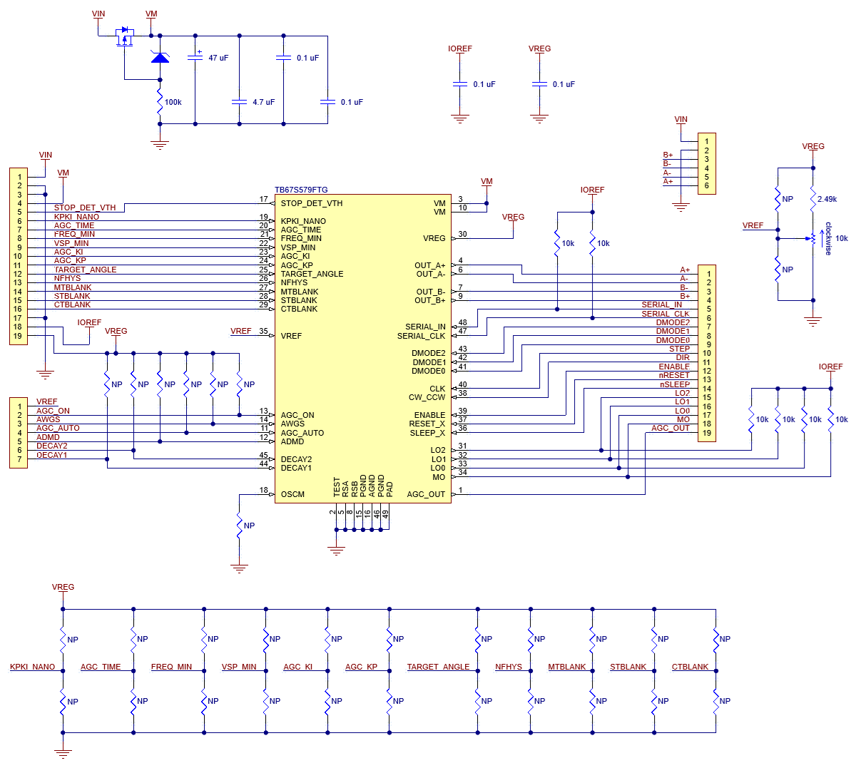 |
Schematic diagram of the TB67S579FTG Stepper Motor Driver Carrier – Full Breakout. |
|---|
Pinout
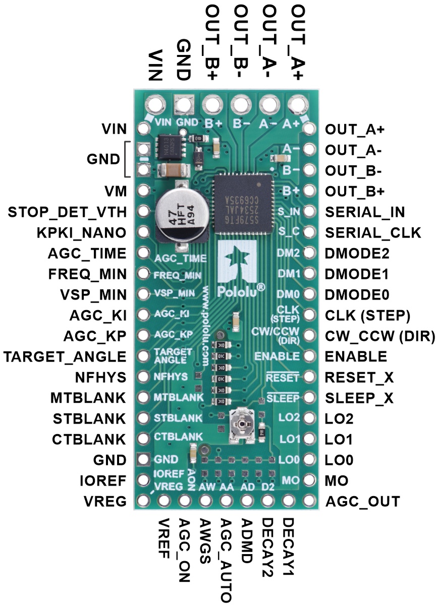 |
The six larger holes along the top edge of the board are the motor and motor power connections. These have a 3.5 mm spacing for compatibility with 3.5mm-pitch terminal blocks (not included), or you can solder wires directly to the board.
The smaller holes along the other sides of the board (which include alternate connection points for the motor and motor power) are all arranged on a 0.1″ (2.54 mm) grid for compatibility with 0.1″ male headers, 0.1″ female headers, solderless breadboards, and other prototyping arrangements that use a 0.1″ grid.
 |
The full-breakout TB67S579FTG Stepper Motor Driver Carrier has smaller through-holes that are compatible with 0.1″ headers and larger motor and power through-holes that work with 3.5mm-pitch terminal blocks (through-hole components not included). |
|---|
Power and motor connections
The driver requires a motor supply voltage of 4.5 V to 34 V to be connected across VIN and GND. This supply should be capable of delivering the expected stepper motor current.
Four, six, and eight-wire stepper motors can be driven by the TB67S579FTG if they are properly connected; a FAQ answer explains the proper wirings in detail.
Warning: Connecting or disconnecting a stepper motor while the driver is powered can destroy the driver. (More generally, rewiring anything while it is powered is asking for trouble.)
Step (and microstep) size
Stepper motors typically have a step size specification (e.g. 1.8° or 200 steps per revolution), which applies to full steps. A microstepping driver such as the TB67S579FTG allows higher resolutions by allowing intermediate step locations, which are achieved by energizing the coils with intermediate current levels. For instance, driving a motor in quarter-step mode will give the 200-step-per-revolution motor 800 microsteps per revolution by using four different current levels.
The resolution (step size) selector inputs (DMODE0, DMODE1, and DMODE2) enable selection from the seven step resolutions according to the table below. These three pins have internal 100 kΩ pull-down resistors, so the driver defaults to full-step mode when these inputs are left disconnected. For the microstep modes to function correctly, the current limit must be set low enough (see below) so that current limiting gets engaged. Otherwise, the intermediate current levels will not be correctly maintained, and the motor will skip microsteps.
| DMODE0 | DMODE1 | DMODE2 | Microstep Resolution |
|---|---|---|---|
| Low | Low | Low | Full step |
| Low | Low | High | Non-circular half step (“A”) |
| Low | High | Low | Circular half step (“b”) |
| Low | High | High | 1/4 step |
| High | Low | Low | 1/8 step |
| High | Low | High | 1/16 step |
| High | High | Low | 1/32 step |
| High | High | High | 1/32 step |
Required control inputs
The rising edge of each pulse to the CLK input corresponds to one microstep of the stepper motor in the direction selected by the CW/CCW pin. These inputs are both pulled low by default through internal 100 kΩ pull-down resistors. For rotation in a single direction, CW/CCW can be left disconnected.
Driver operation is inhibited by default by the internal pull-downs on SLEEP_X, RESET_X, and ENABLE. All three inhibit the driver in different ways, and all three need to be set high before the driver will operate.
For more details on these and the many other inputs and outputs on this driver, refer to the TB67S579FTG datasheet (5MB pdf).
Current limiting
To achieve high step rates, the motor supply is typically higher than would be permissible without active current limiting. For instance, a typical stepper motor might have a maximum current rating of 1 A with a 5 Ω coil resistance, which would indicate a maximum motor supply of 5 V. Using such a motor with 10 V would allow higher step rates, but the current must actively be limited to under 1 A to prevent damage to the motor.
The TB67S579FTG supports such active current limiting, and the trimmer potentiometer on the board can be used to set the current limit:
You will typically want to set the driver’s current limit to be at or below the current rating of your stepper motor. One way to set the current limit is to put the driver into full-step mode and to measure the current running through a single motor coil without clocking the STEP input. The measured current will be equal to the current limit (since both coils are always on and limited to 100% of the current limit setting in full-step mode).
Another way to set the current limit is to measure the VREF voltage and calculate the resulting current limit. The VREF pin voltage is accessible via a small hole that is circled on the bottom silkscreen of the circuit board. The current limit in amps relates to the reference voltage in volts as follows:
``text(Current Limit) = text(VREF) * 0.556 A/V``
or, rearranged to solve for VREF:
``text(VREF) = text(Current Limit) / (0.556 A/V)``
So, the current limit in amps (A) is equal to 0.556 times the VREF voltage in volts (V), and if you a stepper motor rated for 1 A, for example, you can set the current limit to about 1 A by setting the reference voltage to about 1.8 V.
Note: The coil current can be very different from the power supply current, so you should not use the current measured at the power supply to set the current limit. The appropriate place to put your current meter is in series with one of your stepper motor coils. If the driver is in full-step mode, both coils will always be on and limited to 100% of the current limit setting (unlike some other drivers that limit it to about 70% in full-step mode). If your driver is in one of the microstepping modes, the current through the coils will change with each step, ranging from 0% to 100% of the set limit. If Active Gain Control is active, it will also further reduce the actual motor current. See the driver’s datasheet for more information.
Configuration pads
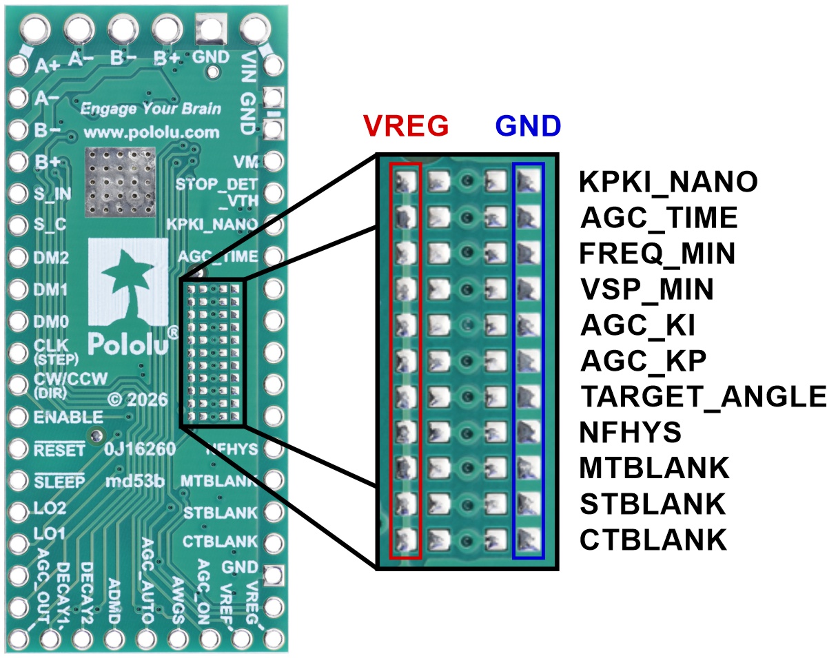
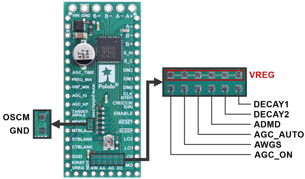
This carrier board includes SMT configuration pads for customizing the default states of some of the pins. The bottom side of the PCB features 0402 pads for setting up voltage dividers for each of the driver’s 11 analog inputs, as shown in the left picture below. The left set of pads is for the top resistor of the voltage divider while the right set of pads is for the bottom resistor, and the pin connects to the middle. Alternatively, if you want to use the serial interface to configure the driver through its internal registers, you can just populate the pull-up resistors (or short across the VREG-side pads).
|
|
Power dissipation considerations
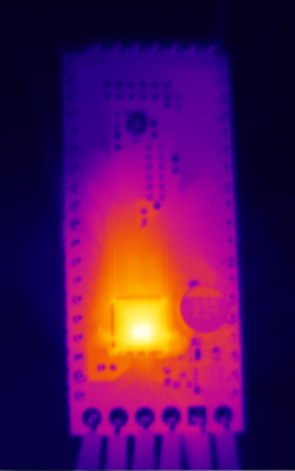 |
Thermal image showing the TB67S579FTG Stepper Motor Driver Carrier – Full Breakout heating up during operation. |
|---|
The TB67S579FTG datasheet states that it can deliver maximum currents up to 2 A per coil, but the actual current you can deliver depends on how well you can keep the IC cool. The carrier’s printed circuit board is designed to draw heat out of the IC, but to supply more than approximately 1.2 A per coil, a heat sink or other cooling method is required. The maximum current also decreases as the supply voltage increases: in our tests, the board could deliver about 1.3 A continuous per coil at 12 V and 1.2 A continuous per coil at 32 V.
This product can get hot enough to burn you long before the chip overheats. Take care when handling this product and other components connected to it.
Please note that measuring the current draw at the power supply will generally not provide an accurate measure of the coil current. Since the input voltage to the driver can be significantly higher than the coil voltage, the measured current on the power supply can be quite a bit lower than the coil current (the driver and coil basically act like a switching step-down power supply). Also, if the supply voltage is very high compared to what the motor needs to achieve the set current, the duty cycle will be very low, which also leads to significant differences between average and RMS currents. Additionally, please note that the coil current is a function of the set current limit, but it does not necessarily equal the current limit setting as the actual current through each coil changes with each microstep.
Related products


Related categories


Coupon Discount
TB67S579FINTRO: Get one or more of #5249 TB67S579FTG Stepper Motor Driver Carrier - Full Breakout at $14.95. This offer is valid through 31 Aug 2026.


Home | Forum | Blog | Support | Ordering Information | Lists | Distributors | BIG Order Form | About | Contact
© 2001–2026 Pololu Corporation