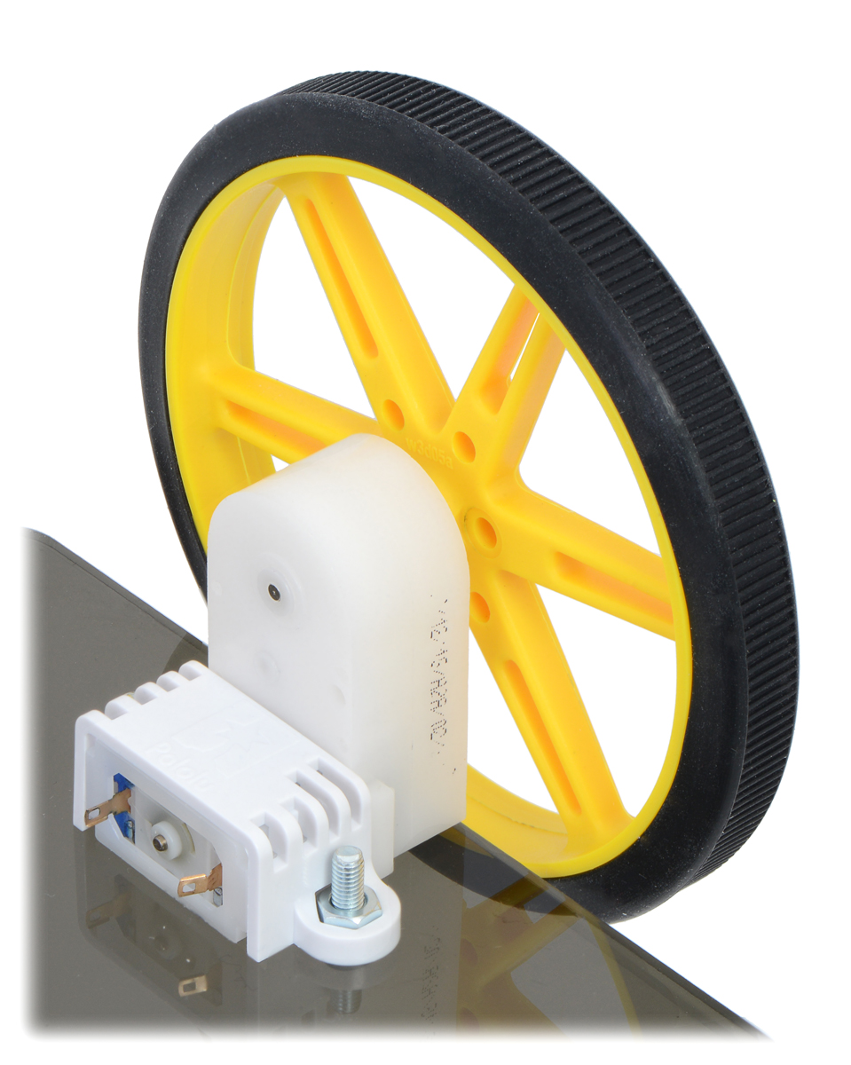
Overview
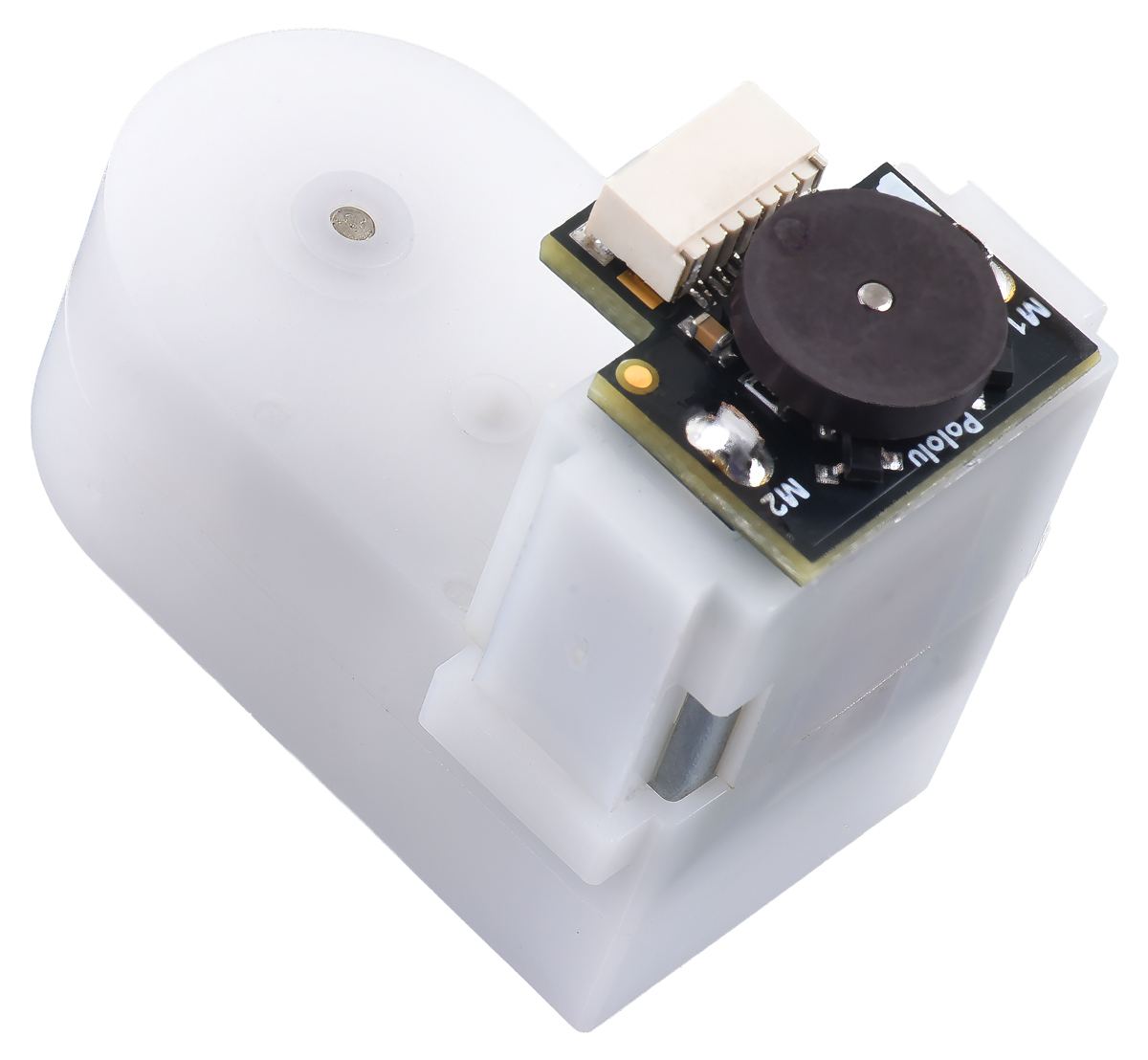
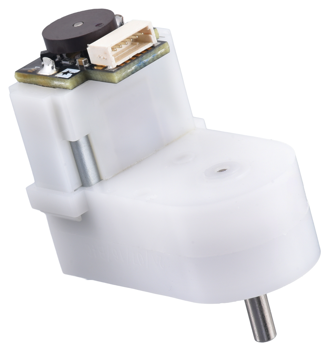
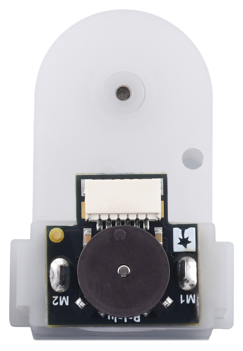
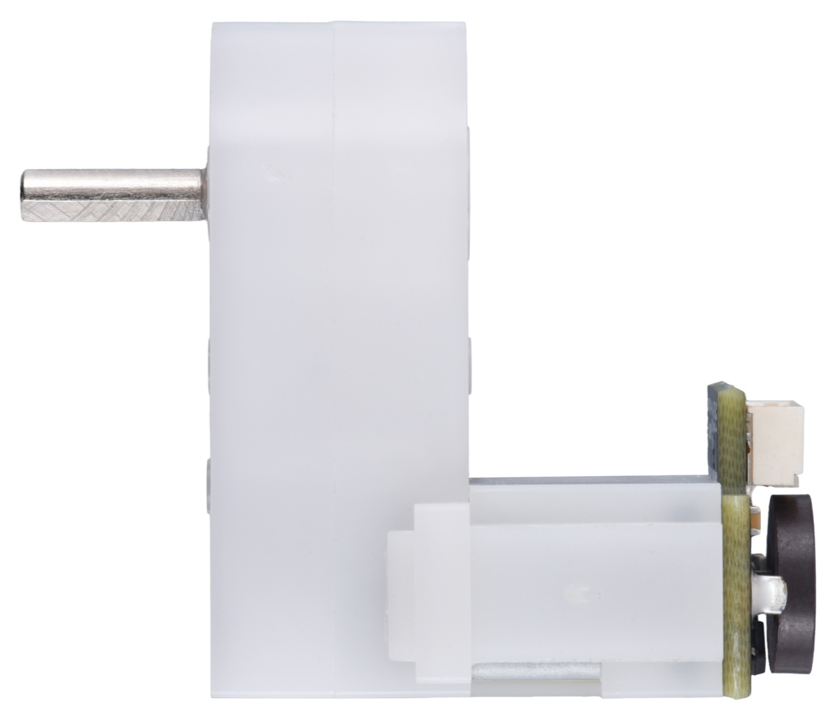
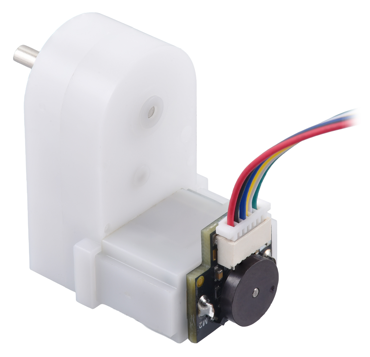
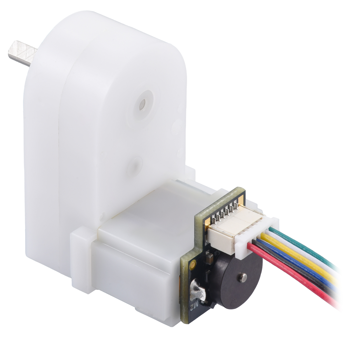
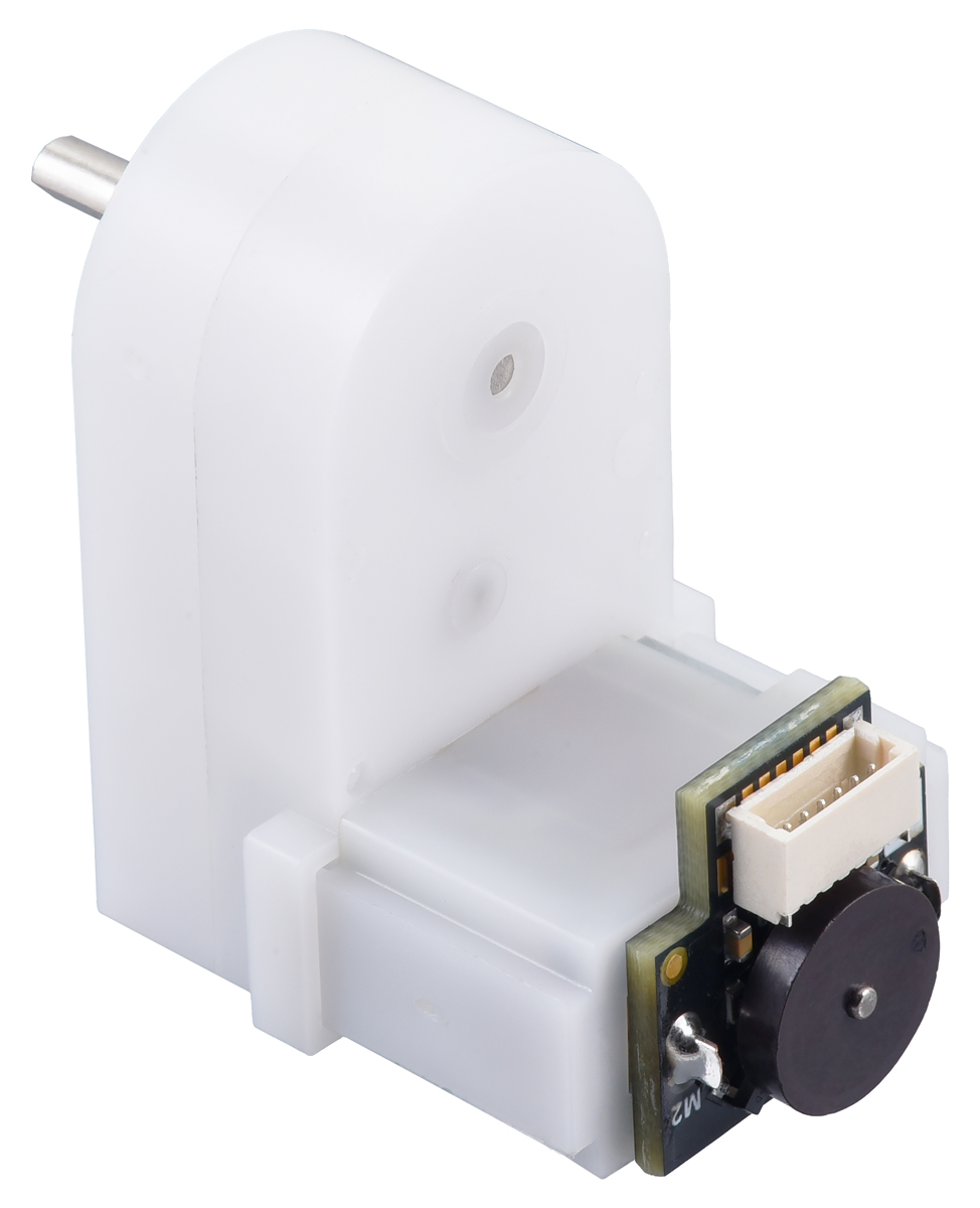
This product is an item #1520 plastic gearmotor (which is the same gearmotor included with our Romi Chassis Kits) with an item #3547 quadrature encoder installed. The encoder senses the rotation of the magnetic disc and provides a resolution of 12 counts per revolution of the motor shaft when counting both edges of both channels, which is corresponds to approximately 1,437 counts per revolution of the gearbox output shaft (i.e., 12 times the gear ratio). The encoder solution fits within the 11.5 mm × 22.5 mm cross section of the motors on three of the four sides, and it extends approximately 5.5 mm past the edge of the fourth side.
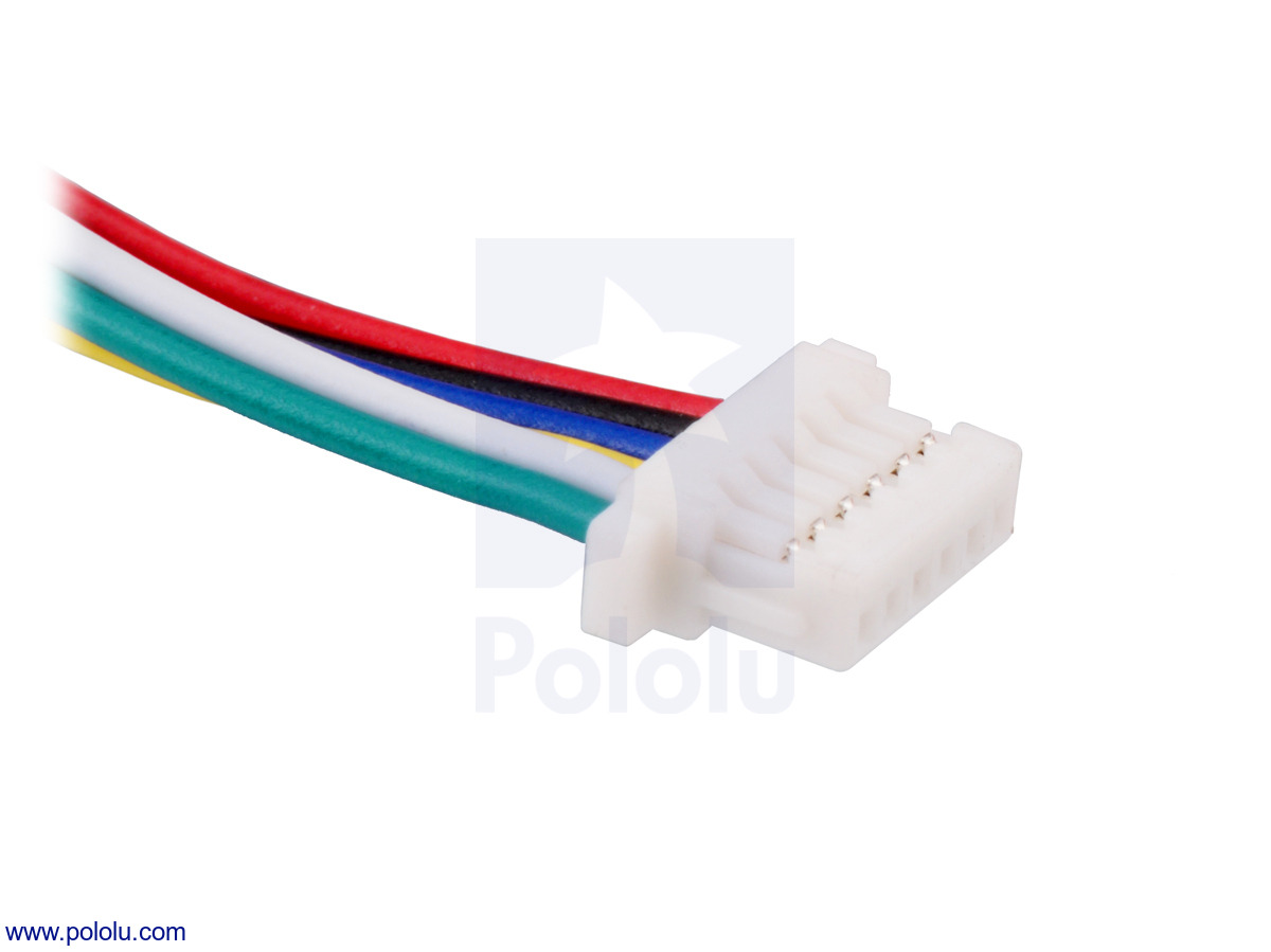
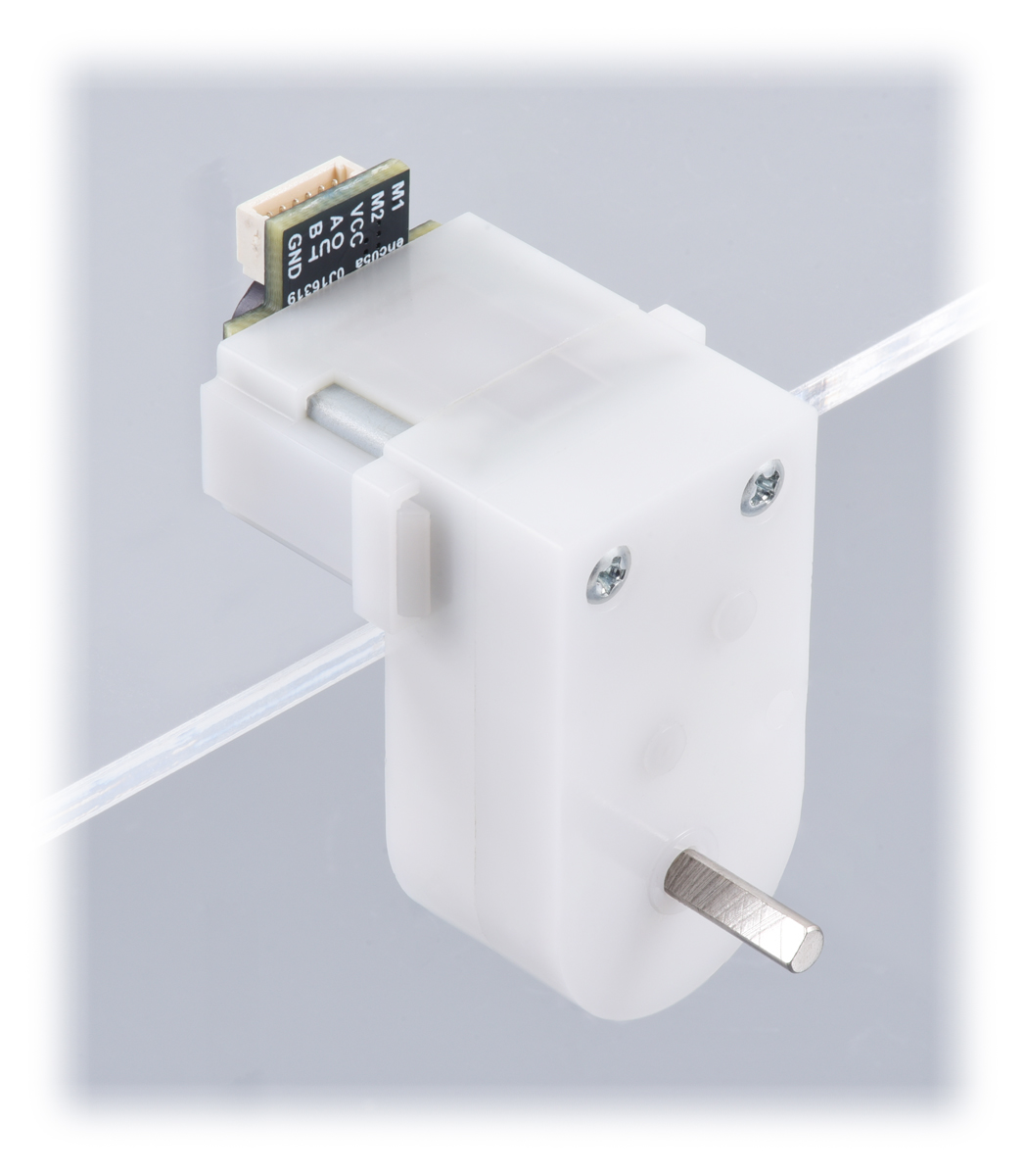
The encoder features a side-entry, 6-pin male JST SH-type connector with a 1mm pitch that is compatible with our 6-pin JST SH-type cables. We also carry a version this gearmotor assembled with a back-entry encoder; the following pictures show a comparison of this side-entry (left) version and the back-entry (right) version:
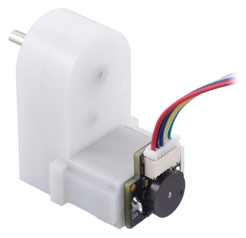 | 120:1 Mini Plastic Gearmotor HP, Offset 3mm D-Shaft Output, with 12 CPR Encoder, Side Connector (cable not included). |
|---|
|
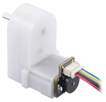 | 120:1 Mini Plastic Gearmotor HP, Offset 3mm D-Shaft Output, with 12 CPR Encoder, Back Connector (cable not included). |
|---|
|
The gearmotor consists of a brushed DC motor with a 120:1 plastic gearbox and a 9.7 mm long, 3 mm diameter “D”-shaped output shaft that is offset from but parallel to the motor shaft. It is intended for use at 4.5 V, though in general, these kinds of motors can run at voltages above and below this nominal voltage, so they should operate comfortably in the 3 V to 6 V range (rotation can start at voltages as low as 0.5 V). Lower voltages might not be practical, and higher voltages could start negatively affecting the life of the motor. The plastic gearbox is protected by a built-in safety clutch that will typically slip before the gear teeth can shear (typically when the load exceeds around 25 oz-in, or 2 kg-cm). Here are the key specifications for the gearmotor at 4.5 V:
| voltage |
no-load performance |
stall extrapolation |
| 4.5 V |
150 RPM, 130 mA |
1.8 kg⋅cm (25 oz⋅in), 1.25 A |
Exact gear ratio: ``(22×38×44×26×30) / (10×11×11×22×9) ~~ bb(119.76)``
Cable options
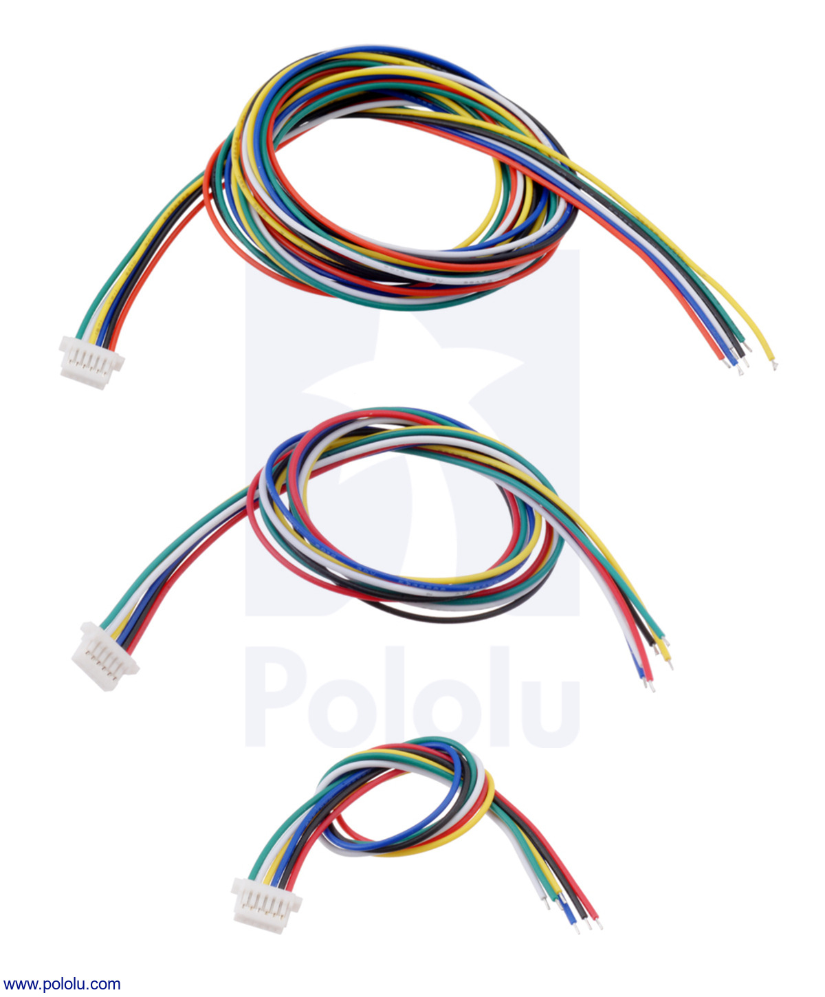
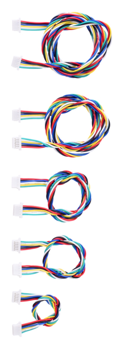
We have two types of cables with matching JST SH-style connectors that can be used with this gearmotor. Single-ended versions have a connector on one end and unterminated wires on the other, while double-ended cables have twisted wires with female connectors on both ends.
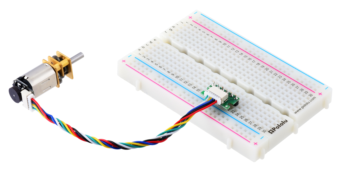
The double-ended cables can be used with our JST SH-style connector breakout boards (available in top-entry and side-entry versions) to easily access the motor and encoder pins on a standard solderless breadboard. The right picture below shows an example of this with our similar micro metal gearmotor encoder.
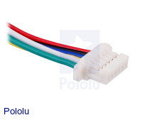 | 6-Pin female JST SH-style connector. |
|---|
|
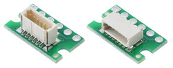 | Top-Entry and Side-Entry Breakout Boards for JST SH-Style Connectors, 6-Pin Male. |
|---|
|
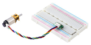 | Side-entry JST SH-style connector breakout board in a breadboard, female-female cable, and encoder with connector mounted on a Micro Metal Gearmotor. |
|---|
|
Pinout
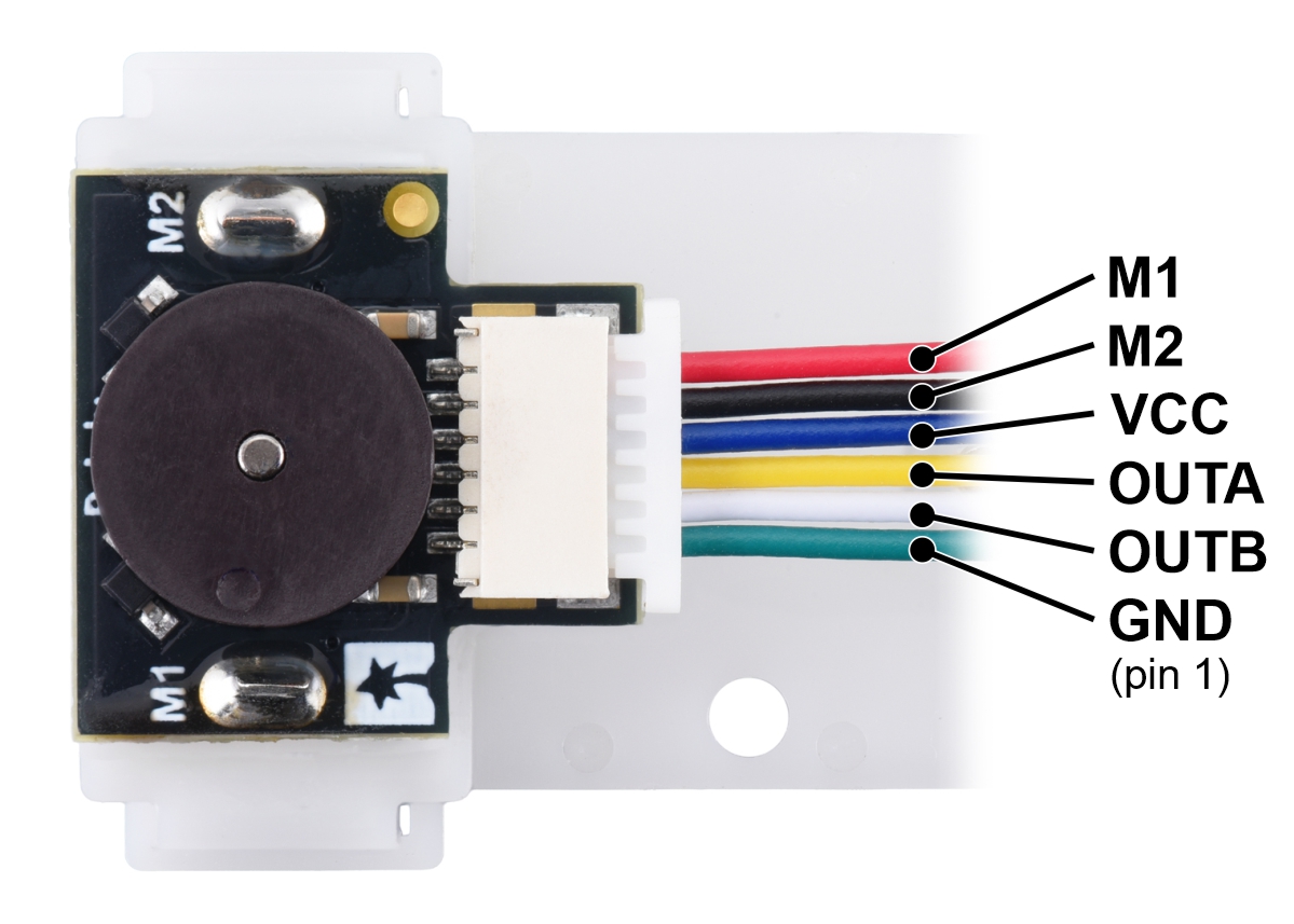
The motor leads are connected to the M1 and M2 connector pins as labeled below, and they can be accessed via the red and black wires when used with our corresponding JST cables. The remaining four connector pins are used to power the sensors and access the two quadrature outputs:
| Pin |
Wire color |
Function |
| 1 |
Green |
encoder GND |
| 2 |
White |
encoder channel B output |
| 3 |
Yellow |
encoder channel A output |
| 4 |
Blue |
encoder Vcc (2.7 V to 18 V) |
| 5 |
Black |
motor power M2 |
| 6 |
Red |
motor power M1 |
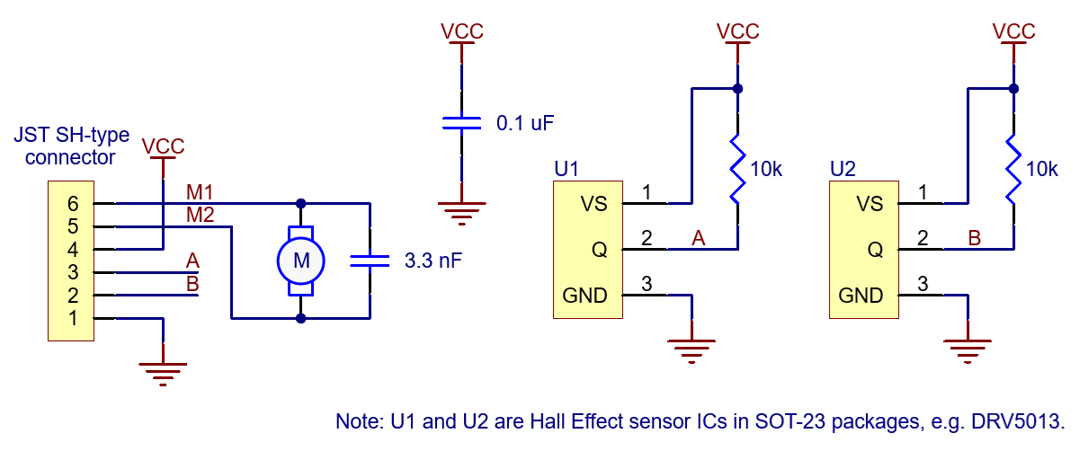
The sensors are powered through the VCC (blue wire) and GND (green wire) pins. VCC can be 2.7 V to 18 V, and the quadrature outputs A and B (yellow and white wires) are digital signals that are either driven low (0 V) by the sensors or pulled to VCC through 10 kΩ pull-up resistors, depending on the applied magnetic field. The sensors’ comparators have built-in hysteresis, which prevents spurious signals in cases where the motor stops near a transition point.
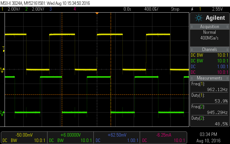 |
Encoder A and B outputs of a magnetic encoder on a high-power (HP) mini plastic gearmotor running at 4.5 V. |
|---|
Encoder schematic diagram
Changing the encoder orientation
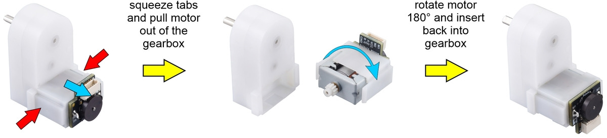
If the encoder location is not convenient for the desired motor mounting orientation, it is possible to remove and rotate the entire motor assembly 180° as shown below:
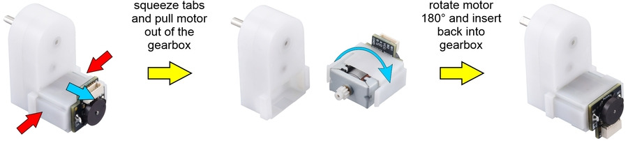 | The motor/encoder can optionally be removed from the gearbox and rotated 180°. |
|---|
|
|
|
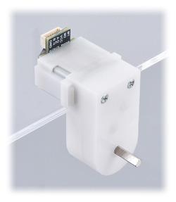 | Rotating the motor/encoder allows alternate motor mounting orientations. |
|---|
|
Available accessories
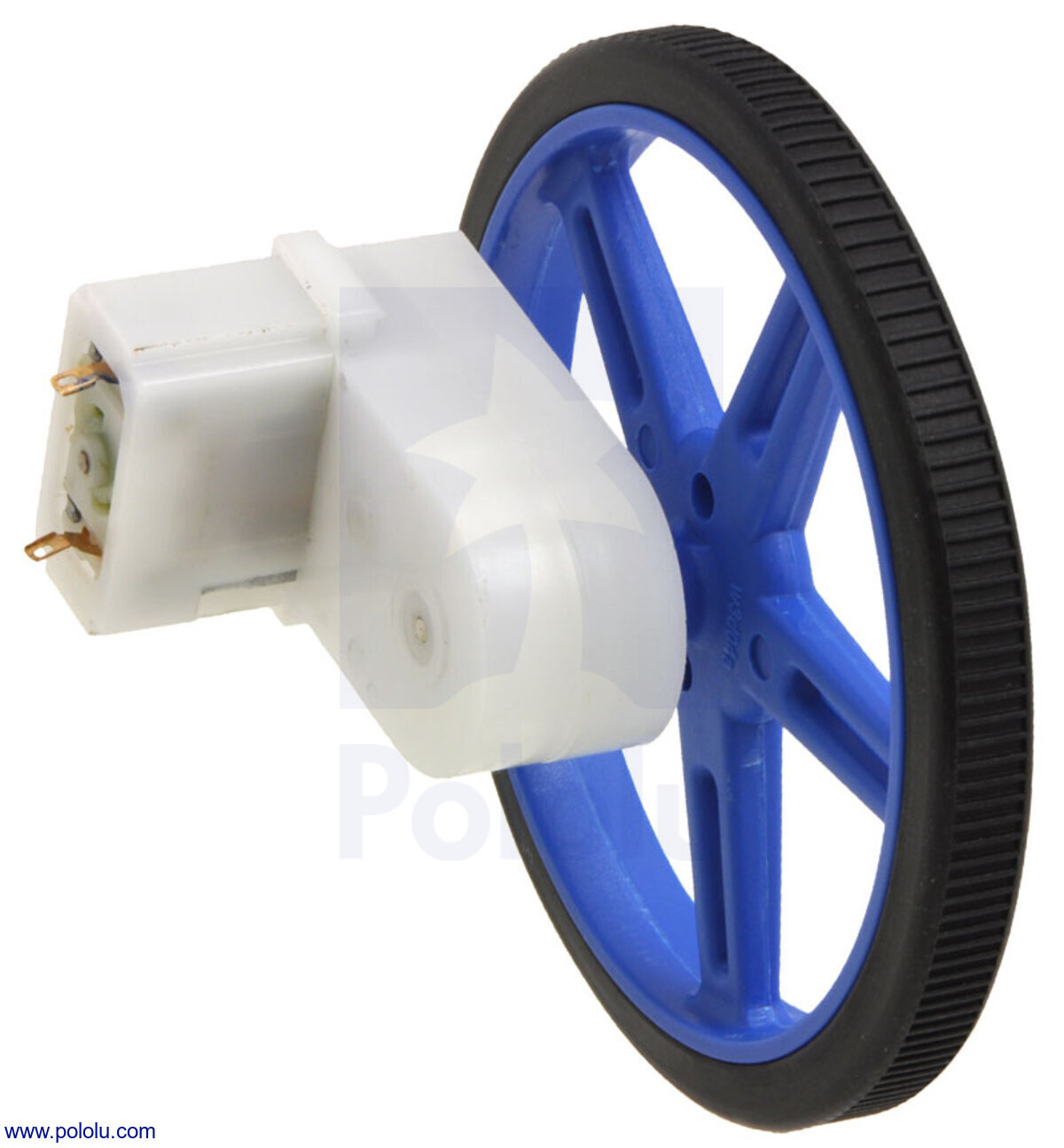
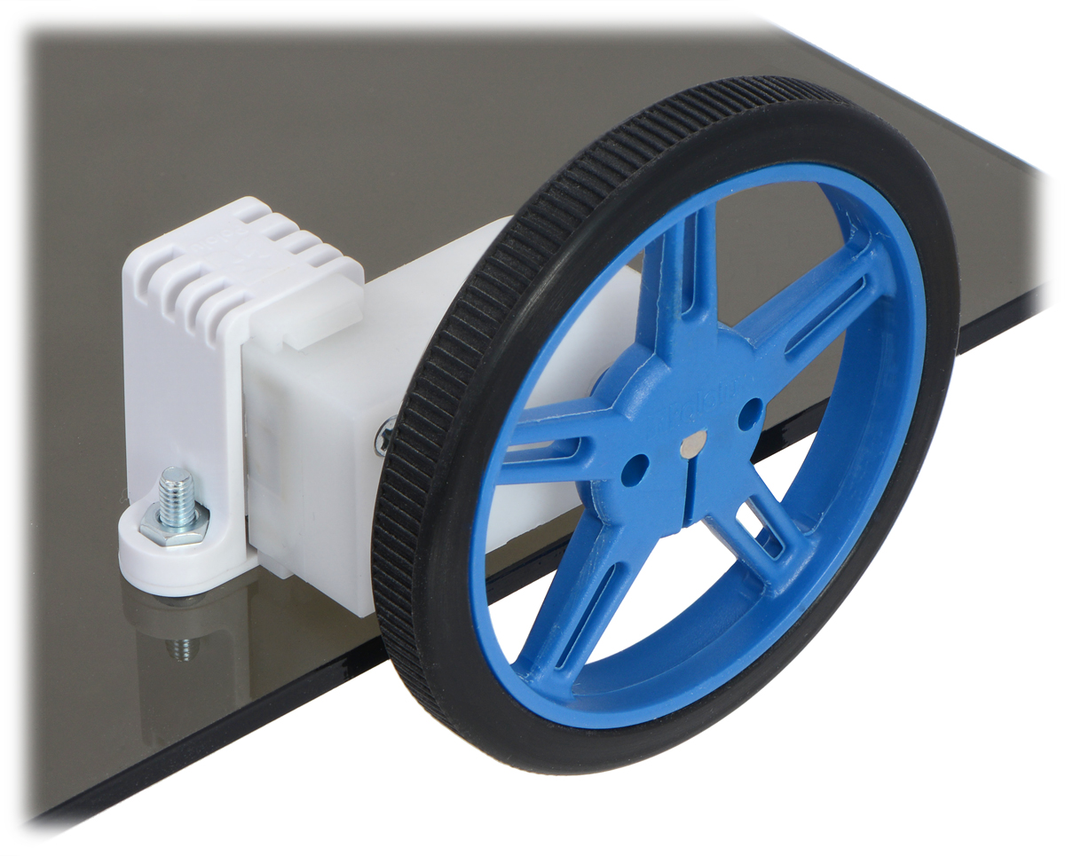
The gearbox’s 3 mm diameter D-shaft output is just like the one on our micro metal gearmotors and is compatible with many Pololu wheels and our 3 mm universal mounting hubs. It is also compatible with our 12mm hex wheel adapter, which enables this motor to be used with many common hobby RC wheels. Wide and tall mounting brackets are also available for securely mounting the gearmotor in different orientations. The pictures below show examples with a different mini plastic gearmotor that has the same relevant dimensions as this product:
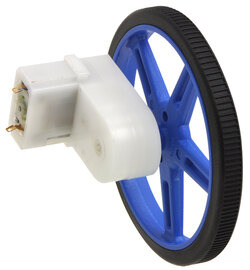 | Mini plastic gearmotor offset 3mm D-shaft output with Pololu wheel. |
|---|
|
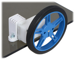 | 60×8mm Pololu wheel and offset mini plastic gearmotor mounted with a tall mini plastic gearmotor bracket (with spacer). |
|---|
|
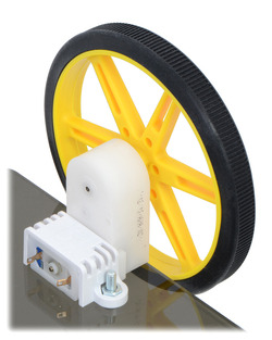 | 80×10mm Pololu wheel and offset mini plastic gearmotor mounted with a wide mini plastic gearmotor bracket. |
|---|
|
 Compare all products in Plastic DC Gearmotors or