Support »
Pololu Motoron Motor Controller User’s Guide
View document on multiple pages.
- 1. Overview
- 2. Contacting Pololu
- 3. Getting started
- 4. Pinout
- 5. LED feedback
- 6. I²C interface
- 7. Serial interface
- 8. Variable reference
- 9. Command reference
- 10. EEPROM settings reference
- 11. Cyclic redundancy check (CRC)
- 12. Reset pin
1. Overview
The Motoron motor controllers are a family of general-purpose modules designed to control brushed DC motors. The Motoron receives commands via I²C or UART serial (depending on which model you have), so only two I/O lines are needed regardless of how many Motorons you connect.
Features and specifications
 |
- Control interface: I²C or UART serial (depending on the model)
- I²C clock speed: up to 400 kHz
- UART serial baud rate: up to 250,000 bps
- Optional cyclic redundancy checking (CRC)
- Configurable motion parameters:
- Max acceleration/deceleration forward/reverse
- Starting speed forward/reverse
- Direction change delay forward/reverse
- PWM frequency: eight options available from 1 kHz to 80 kHz
- Command timeout feature stops motors if the Motoron stops receiving commands
- Configurable automatic error response
- Motor power supply (VIN) voltage measurement
- Two status LEDs
- Motor direction indicator LEDs
- Motoron Arduino library simplifies getting started with an Arduino or compatible controller
- Motoron Python library simplifies using the Motoron with Python or MicroPython
Available versions
 |
The Motoron motor controllers are divided into three different classes with different operating voltage ranges and maximum currents.
- Each Motoron in the 453 class operates from 4.5 V to 44 V and can provide a maximum continuous current of 0.8 A per motor.
- Each Motoron in the 550 class operates from 1.8 V to 22 V and can provide a maximum continuous current of 1.6 A to 1.8 A per motor (depending on the model).
- Each Motoron in the 256 class operates from 4.5 V to 48 V and can provide a maximum continuous current of 1.8 A to 2.2 A per motor (depending on the model).
- Each Motoron in the high-power class has a minimum operating voltage of 6.5 V, can operate up to 30 V or 40 V (depending on the model), and can provide a maximum continuous current of 14 A to 20 A (depending on the model). These high-power models have current sensing and configurable hardware current limiting.
Each of the links in the list above goes to a category on the Pololu website that contains several different Motoron products. Visit the links above to learn the details for each Motoron product, including its operating voltage range, maximum current, control interface, number of channels, and what hardware comes included or soldered.
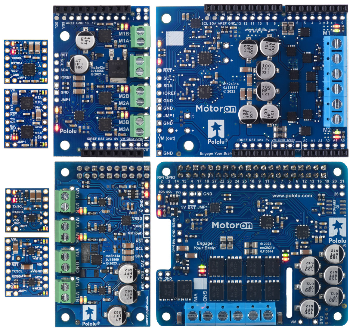
The tables below list the members of the Motoron family and show the key differences among them. Each type is available in several versions to provide different options for the through-hole connectors: they can be purchased as an assembled product with connectors soldered in, as a kit with connectors included but not soldered in, or (for Arduino and Raspberry Pi expansions) as a standalone board without connectors.
| Motoron motor controllers micro versions |
|||||
 M3T453 w/JST connectors  M3T453 w/0.1″ headers |
 M1T550 M1U550 |
 M2T550 M2U550 |
 M1T256 M1U256 |
 M2T256 M2U256 |
|
|---|---|---|---|---|---|
| Control interface: | I²C | I²C or UART serial | |||
| Motor channels: | 3 (triple) | 1 (single) | 2 (dual) | 1 (single) | 2 (dual) |
| Minimum motor supply voltage: |
4.5 V | 1.8 V | 4.5 V | ||
| Absolute max motor supply voltage: |
44 V | 22 V | 48 V | ||
| Recommended max nominal battery voltage: |
32 V | 16 V | 36 V | ||
| Max continuous current per channel: |
0.8 A | 1.8 A | 1.6 A | 2.2 A | 1.8 A |
| Logic voltage range: | 3.0 V to 5.5 V | 3.0 V to 4.9 V(1) | 3.0 V to 5.5 V | ||
| Current sensing: | channels 1 & 2 only | – | – | – | – |
| Current limiting: | – | – | – | – | – |
| Available versions with I²C: |
|||||
| Available versions with UART serial: |
– | ||||
| Price: | $18.95 – $19.95 | $12.49 – $13.49 | $15.95 – $16.95 | $16.95 – $17.95 | $23.95 – $24.95 |
| 1 The M1x550 and M2x550 are not recommended for use with 5V nominal logic. | |||||
| Motoron motor controllers Arduino and Raspberry Pi form factor versions |
||||||
 M3S550  M3H550 |
 M3S256  M3H256 |
 M2S24v14  M2H24v14 |
 M2S24v16  M2H24v16 |
 M2S18v18  M2H18v18 |
 M2S18v20  M2H18v20 |
|
|---|---|---|---|---|---|---|
| Control interface: | I²C | |||||
| Motor channels: | 3 (triple) | 2 (dual) | ||||
| Minimum motor supply voltage: |
1.8 V | 4.5 V | 6.5 V | |||
| Absolute max motor supply voltage: |
22 V | 48 V | 40 V | 30 V | ||
| Recommended max nominal battery voltage: |
16 V | 36 V | 28 V | 18 V | ||
| Max continuous current per channel: |
1.7 A | 2 A | 14 A | 16 A | 18 A | 20 A |
| Logic voltage range: | M3S550 3.1 V to 5.5 V |
3.0 V to 5.5 V | 3.0 V to 5.5 V | |||
| M3H550 3.0 V to 4.9 V(1) |
||||||
| Current sensing/limiting: | – | – | ||||
| Available versions for Arduino: |
M3S550 | M3S256 | M2S24v14 | M2S24v16 | M2S18v18 | M2S18v20 |
| Available versions for Raspberry Pi: |
M3H550 | M3H256 | M2H24v14 | M2H24v16 | M2H18v18 | M2H18v20 |
| Price: | $20.95 – $30.95 | $34.95 – $44.95 | $59.95 – $69.95 | $79.95 – $89.95 | $59.95 – $69.95 | $79.95 – $89.95 |
| 1 The M3H550 is not recommended for use with 5V nominal logic. | ||||||
2. Contacting Pololu
We would be delighted to hear from you about any of your projects and about your experience with the Motoron. If you need technical support or have any feedback you would like to share, you can contact us directly or post on our forum. Tell us what we did well, what we could improve, what you would like to see in the future, or anything else you would like to say!
3. Getting started
3.1. Choosing the power supply and motor
The information in this section can help you select a power supply and motor that will work with the Motoron.
The Motoron is designed to work with brushed DC motors. These motors have two terminals such that when a DC voltage is applied to the terminals, the motor spins.
When selecting the components of your system, you will need to consider the voltage and current ratings of each component:
- The voltage range of your power supply is the range of voltages you expect your power supply to produce while operating. There is usually some variation in the output voltage so you should treat it as a range instead of just a single number. In particular, keep in mind that a fully-charged battery might have a voltage that is significantly higher than its nominal voltage.
- The current limit of a power supply is how much current the power supply can provide. Note that the power supply will not force this amount of current through your system; the properties of the system and the voltage of the power supply determine how much current will flow, but there is a limit to how much current the power supply can provide.
- The operating voltage range of a Motoron is the absolute range of voltages that can be supplied to the Motoron’s VIN and GND pins, which power the motors. The Motoron requires a DC power supply. The operating voltage range of each Motoron is listed on the Motoron category page and on each Motoron’s product page, both in the summary at the top and in the “Specifications” tab.
- The continuous output current per channel of a Motoron is the maximum amount of current that the Motoron can continuously provide to each motor. The output current for each Motoron is listed on the Motoron category page and on each Motoron’s product page, both in the summary at the top and in the “Specifications” tab.
- The rated voltage of a DC motor is the voltage at which the DC motor was designed to run. You can apply voltages to the motor that are higher or lower than its rated voltage, but higher voltages bring a risk of overheating the motor or reducing its lifetime.
- The no-load current of a DC motor is the current that the motor will draw if you apply the rated voltage to the motor while its output is not connected to anything.
- The stall current of a DC motor is the current that the motor will draw if you apply the rated voltage to the motor while forcing its output shaft to remain stationary.
There are guidelines you should be aware of when selecting the components of your system:
- The voltage of your power supply should generally be greater than or equal to the rated voltage of each DC motor. Otherwise, you will not get the full performance that the motor was designed for. If your power supply’s voltage is much higher than the rated voltage of a DC motor, you might account for that by using lower speeds for that motor in your commands to the Motoron.
- The voltage of your power supply should be within the operating voltage range of the Motoron. Otherwise, the Motoron could malfunction or (in the case of high voltages) be damaged. Additionally, we recommend that the voltage of your power supply should be at least 6 V less than the absolute maximum, which leaves a safety margin for ripple voltage on the supply line. Note that a fully-charged battery will have a voltage much higher than the nominal voltage.
- The typical current draw you expect for each motor should be less than the Motoron’s continuous current per motor. Each motor’s typical current draw will depend on your power supply voltage, the speeds you command the motor to move, and the current ratings of the motor. For the Motoron M1T550, M1U550, M2T550, M2U550, M3S550, M3H550, M1T256, M1U256, M2T256, M2U256, M3S256, and M3H256, a motor that draws too much current could trigger the Motoron’s overcurrent or overtemperature faults, which shut down the motor. For the Motoron M2S and M2H, a motor that draws too much current could cause the board to overheat, resulting in permanent damage.
- The current limit of the power supply should be higher than the typical total current draw for all the motors in your system. Furthermore, it is generally good for the current limit to be much higher than that so your system can smoothly handle the times where the motors are drawing more than the typical current, for example when they are accelerating or encountering extra resistance.
3.2. Connecting everything
3.2.1. Connecting a micro Motoron with an I²C interface
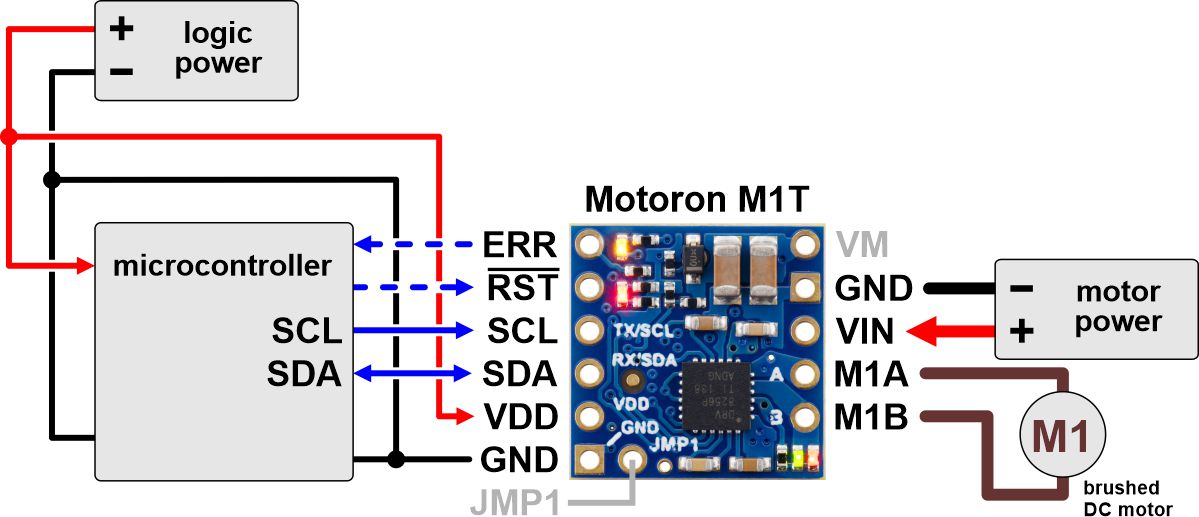
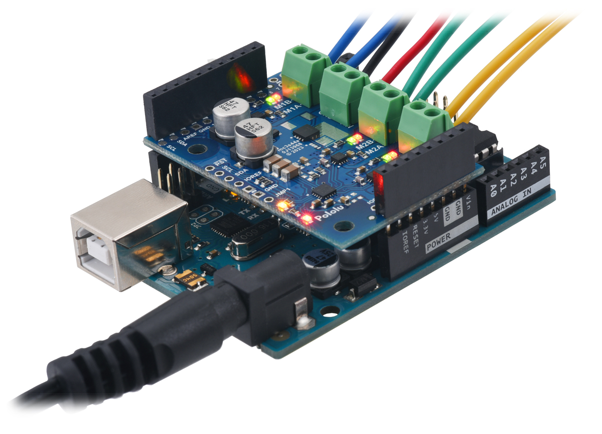
This section explains how to connect motor power, motors, and a microcontroller to the Motoron M1T550, M2T550, M1T256, M2T256, and M3T453, micro-sized controllers with an I²C interface.
 |
Typical wiring diagram for connecting a microcontroller to a Motoron M1T256/M1T550 Single I²C Motor Controller. |
|---|
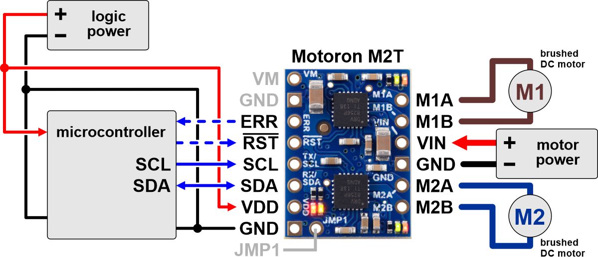 |
Typical wiring diagram for connecting a microcontroller to a Motoron M2T256/M2T550 Dual I²C Motor Controller. |
|---|
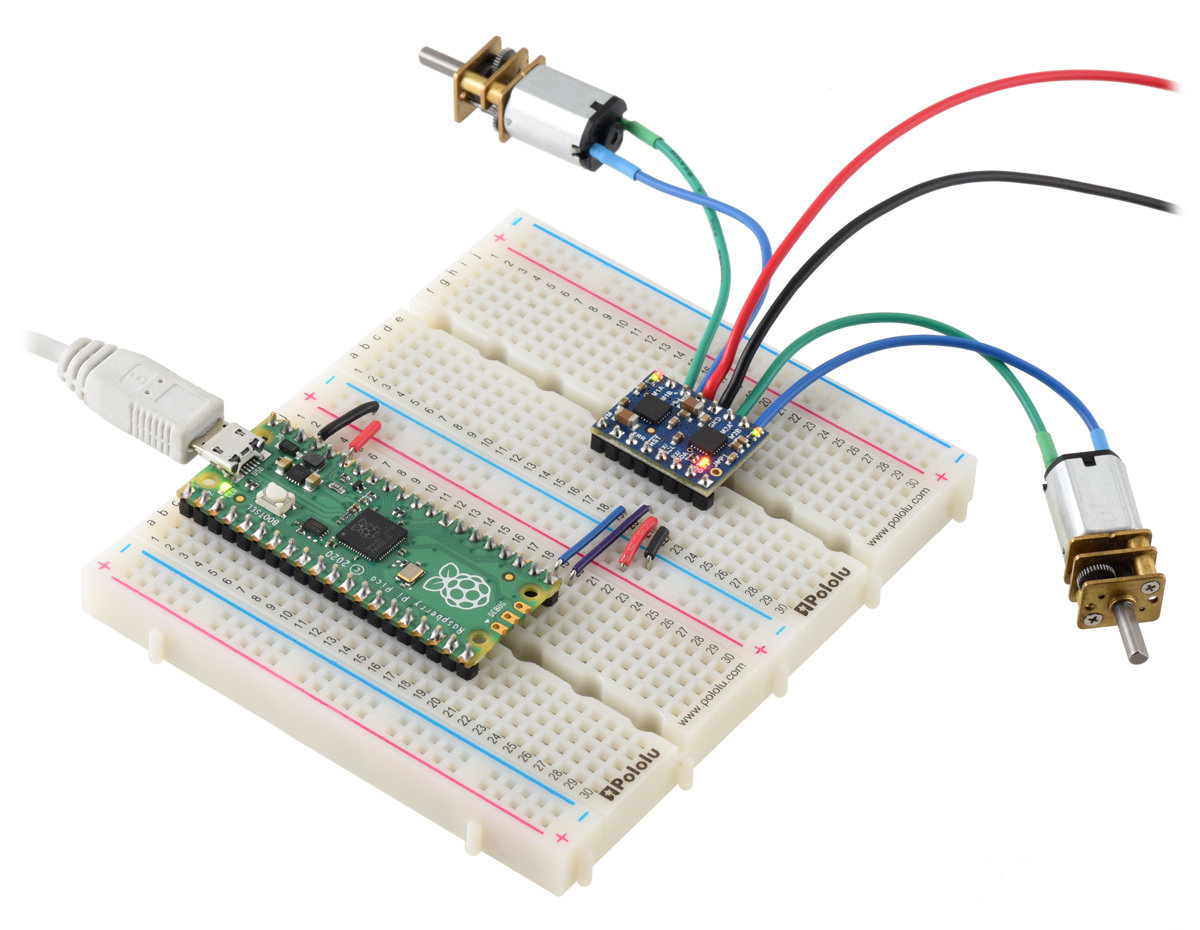 |
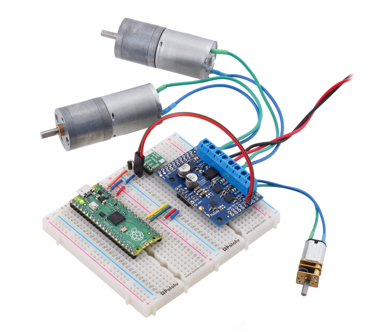
A Raspberry Pi Pico on a breadboard using a Motoron M2T256/M2U256 Dual Motor Controller to control two motors. |
|---|
 |
Typical wiring diagram for connecting a microcontroller to a Motoron M3T453 Triple I²C Motor Controller with JST SH-Style Connectors. |
|---|
 |
Typical wiring diagram for connecting a microcontroller to a Motoron M3T453 Triple I²C Motor Controller with 0.1″-Pitch Through-Holes. |
|---|
Making connections to 0.1"-pitch through-holes
You can buy a version of the Motoron that comes with male header pins already soldered, or you can buy a version with header pins included and do the soldering yourself. After your Motoron has header pins securely soldered to it, you can push the Motoron into a breadboard or connect its pins to jumper wires. Alternatively, you can make connections by directly soldering wires to the board. Regardless of which of these methods you choose, soldering is necessary to make reliable connections.
Making connections to JST SH-style connectors
If your Motoron version has a 4-pin JST SH-style connector, it is compatible with 4-pin JST SH-style cables. This 4-pin connector provides GND, VDD, SDA, and SCL. It is compatible with Sparkfun’s Qwiic and Adafruit’s STEMMA QT and also works with the Pololu Isolated USB-to-I²C Adapter with Isolated Power. If your Motoron has two 4-pin JST SH-style connectors, both connectors provide access to the same nodes you can use them interchangeably. If you are controlling multiple Motorons, you can chain them together using JST cables in order to connect them all to the same I²C bus.
| Pin | Typical wire color | Name | Function |
|---|---|---|---|
| 1 | Black | GND | Ground |
| 2 | Red | VDD | Logic voltage |
| 3 | Blue | SDA | I²C data |
| 4 | Yellow | SCL | I²C clock |
If your Motoron has a 2-pin JST SH-style connector, it is compatible with 2-pin JST SH-style cables. This 2-pin connector provides the power outputs for a single motor. It is compatible with JST SH-Style Connector Boards for Micro Metal Gearmotors.
| Pin | Typical wire color | Name | Function |
|---|---|---|---|
| 1 | Black | M1B, M2B, M3B | Motor output |
| 2 | Red | M1A, M2A, M3A | Motor output |
Connecting motor power and motors
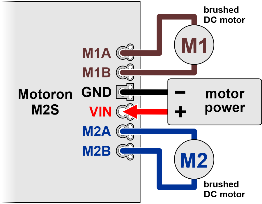
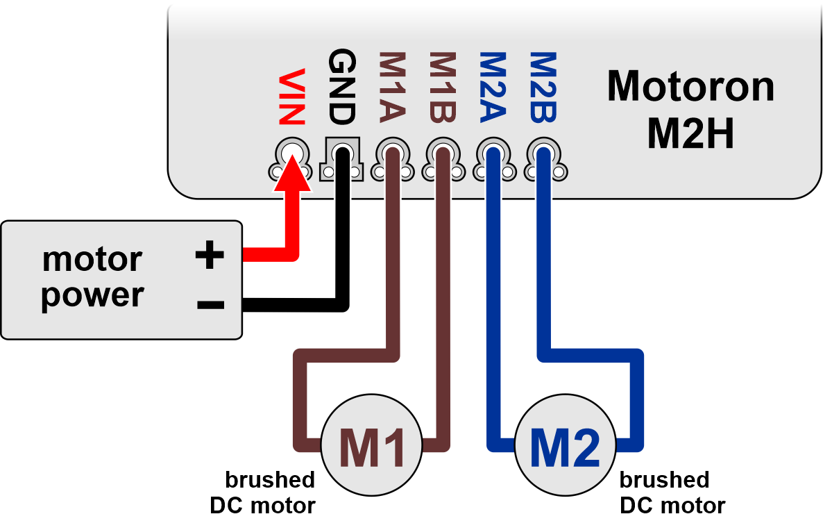
The negative terminal of the motor power supply should be connected to the GND pin on the Motoron that is adjacent to VIN. The positive terminal of the motor power supply should be connected to the VIN pin. Note that connecting power to VIN does not power the Motoron’s microcontroller and does not cause any LEDs to turn on.
Each motor should have one lead connected to an MxA pin (M1A, M2A, or M3A) and the other lead connected to the MxB pin with the matching motor number. The Motoron’s concept of “forward” corresponds to MxA driving high while MxB drives low, so you might consider this when deciding which motor lead connects to which Motoron pin. You can also flip the wires later if you want to flip the direction of motion (assuming one side of the connection does not use a keyed connector).
Connecting a controller or adapter
You will need a controller with an I²C interface to send commands to the Motoron. The Motoron’s GND, SCL, and SDA pins should be connected to the corresponding pins of the controller board, and the Motoron’s logic voltage (VDD) should be connected to the logic voltage supply of the controller board (the allowable logic voltage range can be found in the specifications for your particular Motoron). The Motoron does not supply power to the controller board.
Alternatively, if you want to control the Motoron from a computer via USB, you can use an isolated USB-to-I²C adapter with isolated power which is capable of providing either 3.3 V or 5 V to power the Motoron’s logic voltage. Alternatively, you can use a isolated USB-to-I²C adapter that does not provide power and provide the logic power some other way. Either way, the Motoron’s GND, SCL, SDA, and VDD pins must be connected to the adapter.
Once you make the GND and logic power connections and turn on the logic power, you should see the Motoron’s yellow LED blink. The red LED will also turn on unless something is communicating with the Motoron and causing it to turn the LED off.
You can connect multiple Motorons to the same I²C bus. To control multiple Motorons on the same I²C bus independently, you will need to configure each Motoron to have a unique I²C address, as described in Section 3.5.
3.2.2. Connecting a micro Motoron with a serial interface
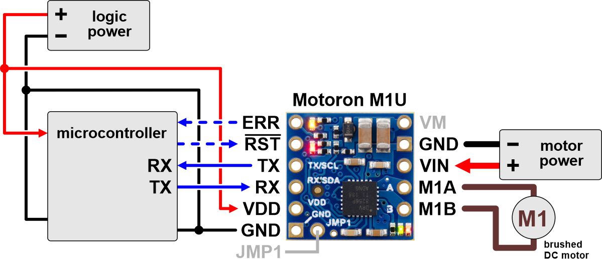
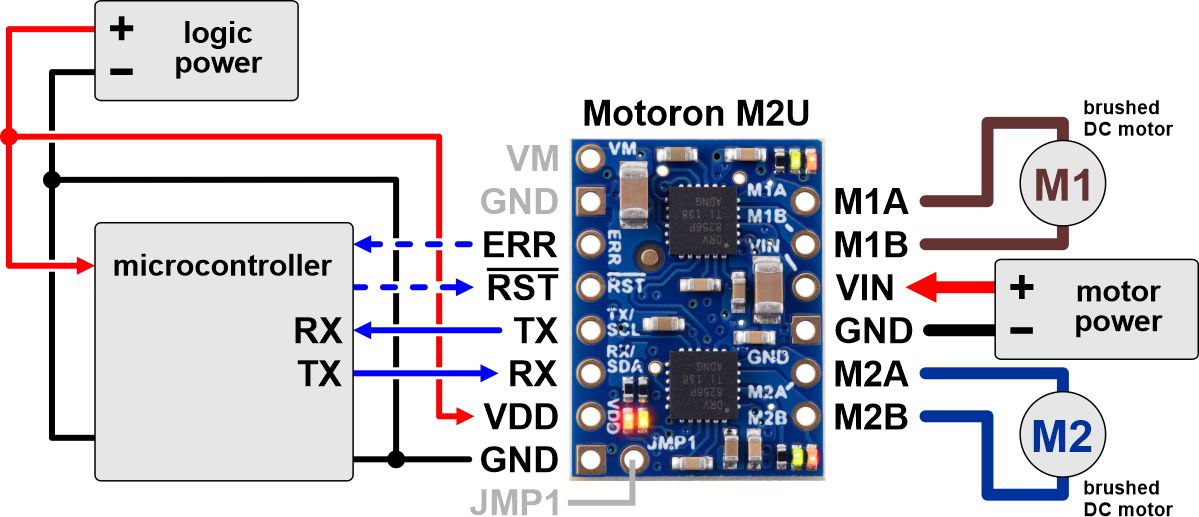
This section explains how to connect motor power, motors, and a microcontroller to the Motoron M1U550, M2U550, M1U256, and M2U256, micro-sized controllers with a UART serial interface.
 |
Typical wiring diagram for connecting a microcontroller to a Motoron M1U256/M1U550 Single Serial Motor Controller. |
|---|
 |
Typical wiring diagram for connecting a microcontroller to a Motoron M2U256/M2U550 Dual Serial Motor Controller. |
|---|
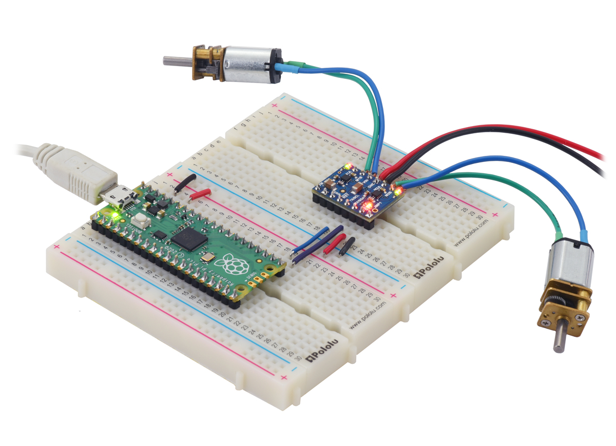 |
A Raspberry Pi Pico on a breadboard using a Motoron M2T550/M2U550 Dual Motor Controller to control two motors. |
|---|
Making connections
You can buy a version of the Motoron that comes with male header pins already soldered, or you can buy a version with header pins included and do the soldering yourself. After your Motoron has header pins securely soldered to it, you can push the Motoron into a breadboard or connect its pins to jumper wires. Alternatively, you can make connections by directly soldering wires to the board. Regardless of which of these methods you choose, soldering is necessary to make reliable connections.
Connecting motor power and motors
The negative terminal of the motor power supply should be connected to the GND pin on the Motoron that is adjacent to VIN. The positive terminal of the motor power supply should be connected to the VIN pin. Note that connecting power to VIN does not power the Motoron’s microcontroller and does not cause any LEDs to turn on.
Each motor should have one lead connected to an MxA pin (M1A or M2A) and the other lead connected to the MxB pin with the matching motor number. The Motoron’s concept of “forward” corresponds to MxA driving high while MxB drives low, so you might consider this when deciding which motor lead connects to which Motoron pin. You can also flip the wires later if you want to flip the direction of motion.
Connecting a controller
You will need a controller with a UART serial interface to send commands to the Motoron. The Motoron’s GND pin should be connected to a ground pin of the controller board. The Motoron’s RX pin should be connected to the TX pin of the controller board. If you want to read data from the Motoron, then the Motoron’s TX pin should be connected to the RX pin of the controller board. The Motoron’s logic voltage (VDD) should be connected to the logic voltage supply of the controller board (the allowable logic voltage range can be found in the specifications for your particular Motoron). The Motoron does not supply power to the controller board.
Once you make the GND and logic power connections and turn on the logic power, you should see the Motoron’s yellow LED blink. The red LED will also turn on unless something is communicating with the Motoron and causing it to turn the LED off.
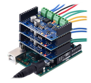
3.2.3. Connecting a Motoron shield for Arduino
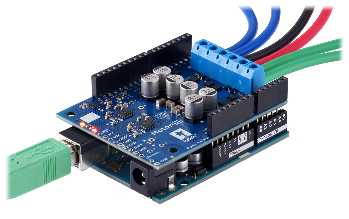
This section explains how to connect motor power, motors, and a microcontroller to the Motoron M3S550, M3S256 and the M2S family, which are designed to be shields for an Arduino.
Connecting terminal blocks
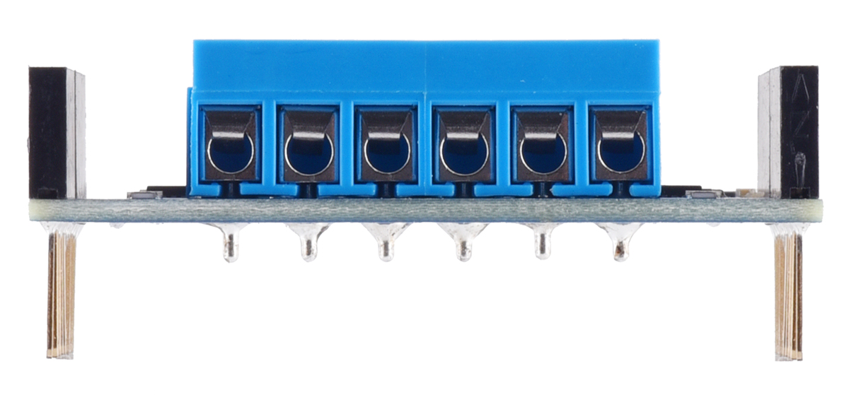
For the Motoron M3S550 and M3S256, we generally recommend using green 3.5mm-pitch terminal blocks for the motor power and motor connections. If you have an assembled version of the Motoron, these terminal blocks come soldered to the board. Otherwise, you will need to solder them yourself. They should be soldered to the larger through holes for board power and motor outputs (GND, VIN, M1A, M1B, M2A …).
You can use blue 5mm-pitch terminal blocks if your current requirements are not too high and you can ensure that there is adequate spacing between any stacked boards in your system to prevent short circuits. This type of terminal block is included with the Motoron M3S550, M3S256, and M2S kit versions and comes soldered to the fully assembled versions of the Motoron M2S controllers. The 5mm blue terminal blocks are rated for 16 A so for higher-current applications we recommend soldering thick wires directly to the board. If you decide to use the 5mm terminal blocks, we recommend using the tabs on the side of the terminal blocks to connect them together before soldering them to the Motoron (see our video about how to install terminal blocks for more information).
We recommend only using the 5mm blue terminal blocks on Motoron shields that are at the top of a stack. Using those terminal blocks on two adjacent boards in a stack is likely to cause short circuits because they are taller than the headers.
|
|
Connecting motor power and motors
|
|
The negative terminal of the motor power supply should be connected to the Motoron’s large GND pin or the smaller pins next to it. The positive terminal of the motor power supply should be connected to the Motoron’s large VIN pin or the smaller pins next to it. These GND and VIN connections are required for each Motoron in a stack of Motorons. Connecting two Motorons via stackable headers does not connect their VIN pins at all, and it does not connect their GND pins in a way that is meant to carry the large currents involved in motor control. Note that connecting power to VIN does not power the Motoron’s microcontroller and does not cause any LEDs to turn on.
Each motor should have one lead connected to an MxA pin (M1A, M2A, or M3A) and the other lead connected to the MxB pin with the matching motor number. The Motoron’s concept of “forward” corresponds to MxA driving high while MxB drives low, so you might consider this when deciding which motor lead connects to which Motoron pin. You can also flip the wires later if you want to flip the direction of motion.
Connecting a controller
|
|
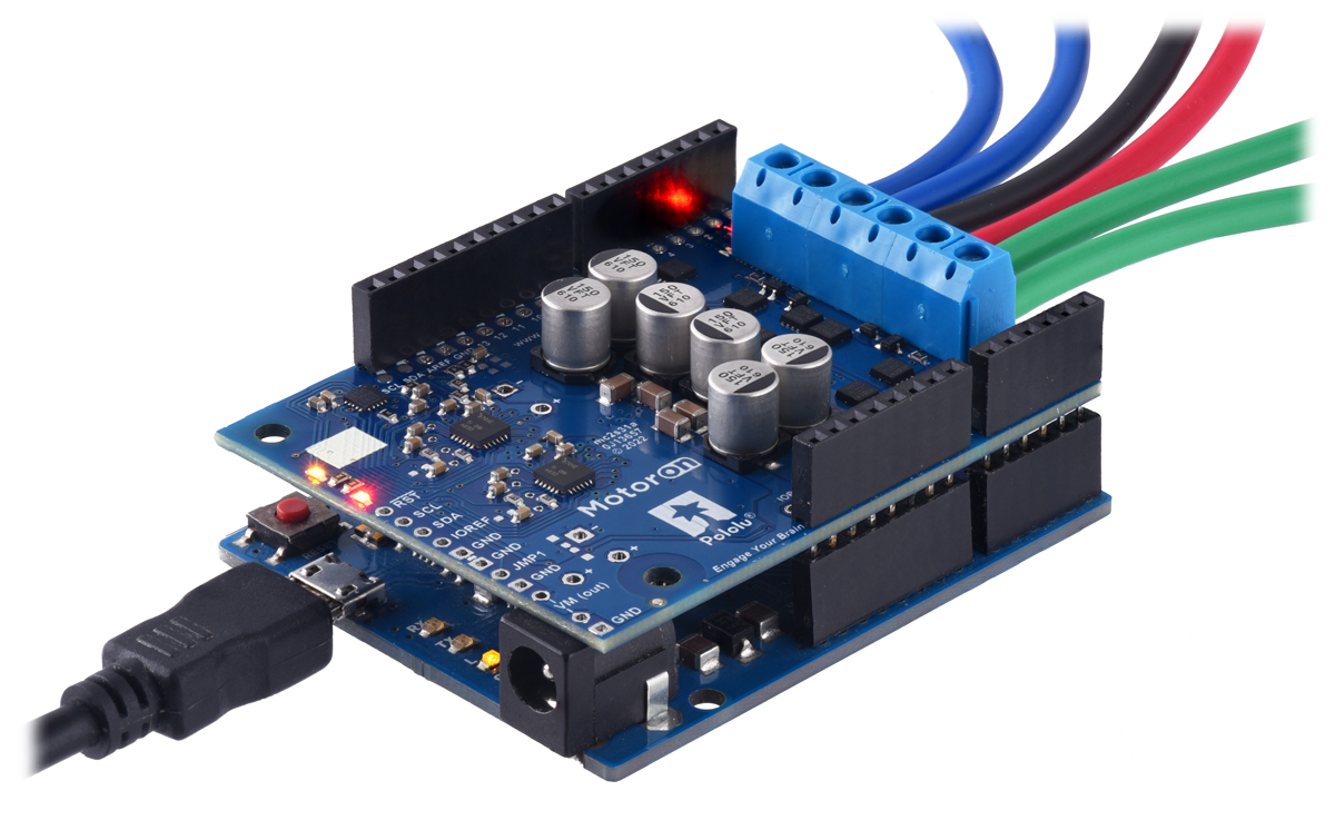
The Motoron shields for Arduino are designed to be plugged into the female headers of an Arduino or Arduino-compatible board that has the shape of the Arduino Leonardo or Arduino Uno R3 using stackable female headers or male headers soldered to the Motoron.
Plugging the Motoron into a controller this way connects the GND, SDA, and SCL pins of both boards, allowing the Arduino to communicate with the Motoron via I²C. It also powers the Motoron’s microcontroller from the Arduino’s IOREF pin. For most Motoron shields, the Motoron’s logic voltage (which powers the microcontroller) comes directly from IOREF. On the Motoron M3S550 shield, the IOREF pin supplies power to a 3.3 LDO regulator and the output of that regulator is the logic voltage.
 |
Motoron M2S shield being controlled by an Arduino Uno. Electrical tape is used on the USB Type-B connector to help prevent shorts. |
|---|
If you plug a Motoron M2S shield directly into an Arduino Uno or similar board, the tall USB connector can touch the Motoron and potentially cause a short circuit. Although that part of the Motoron M2S shield is protected by an insulating solder mask, we recommend adding electrical tape to the top of the USB connector to protect against this, as shown above.
The Motoron does not need to be connected directly to the Arduino: it can be connected through another shield (including other Motoron shields) as long as those boards pass the GND, SCL, SDA, and logic voltage connections through.
You can also connect the Motoron to a controller board that has a different shape as long as you make the same connections. The Motoron’s GND, SCL, and SDA pins should be connected to the corresponding pins on the controller board, and IOREF should be connected to the logic voltage supply of the controller board (the allowable logic voltage range can be found in the specifications for your particular Motoron).
|
|
After you have connected one Motoron shield to a controller, you can connect other Motoron shields to the same controller simply by stacking them above or below the first one.
Once you make the GND and logic power connections and turn on the logic power, you should see the Motoron’s yellow LED blink. The red LED will also turn on unless something is communicating with the Motoron and causing it to turn the LED off.
Powering the Arduino
By default, the Motoron does not supply power to the Arduino, so you will need to power your Arduino separately. However, there are options for powering the controllers, as documented in Section 4.3 for the M3S550/M3S256 and Section 4.5 for the M2S shields.
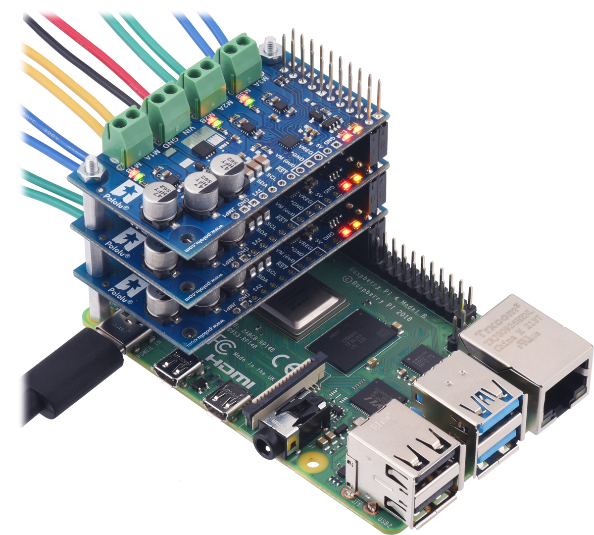
3.2.4. Connecting a Motoron controller for Raspberry Pi
This section explains how to connect motor power, motors, and a microcontroller to the Motoron M3H550, M3H256 and the M2H family, which are designed to be plugged into a Raspberry Pi.
Connecting terminal blocks
For the Motoron M3H550 and M3H256, we generally recommend using green 3.5mm-pitch terminal blocks for the motor power and motor connections. If you have an assembled version of the Motoron, these terminal blocks come soldered to the board. Otherwise, you will need to solder them yourself. They should be soldered to the larger through holes for board power and motor outputs (GND, VIN, M1A, M1B, M2A, …).
You can use blue 5mm-pitch terminal blocks if your current requirements are not too high and you can ensure that there is adequate spacing between any stacked boards in your system to prevent short circuits. This type of terminal block is included with the Motoron M3H550, M3H256 and M2H kit versions and come soldered to the fully assembled versions of the Motoron M2H controllers. The 5mm blue terminal blocks are rated for 16 A so for higher-current applications we recommend soldering thick wires directly to the board. If you decide to use the 5mm terminal blocks, we recommend using the tabs on the side of the terminal blocks to connect them together before soldering them to the Motoron (see our video about how to install terminal blocks for more information).
If you want to stack multiple Motorons using 5mm terminal blocks, should trim the terminal block leads on the bottom side of the board (e.g. using a flush cutter) and use hex nuts in addition to 11mm standoffs (both of which are provided with the assembled and kit versions) between each board to space them out.
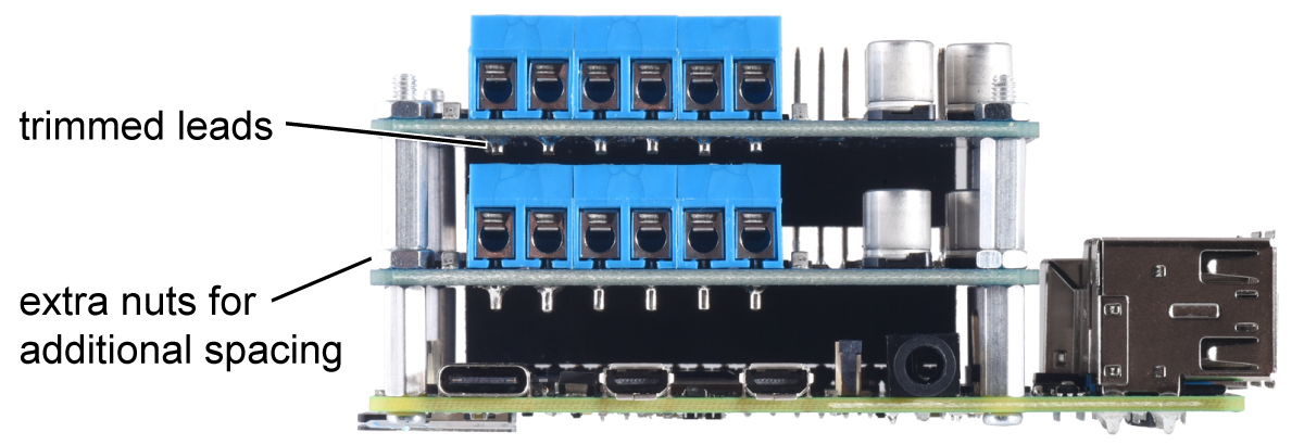 |
Two Motoron M2H boards with terminal blocks can be stacked if you trim the leads on the terminal blocks and space out each board using hex nuts in addition to the 11mm standoffs. |
|---|
Connecting motor power and motors
|
|
The negative terminal of the motor power supply should be connected to the Motoron’s large GND pin or the smaller pins next to it. The positive terminal of the motor power supply should be connected to the Motoron’s large VIN pin or the smaller pins next to it. These GND and VIN connections are required for each Motoron in a stack of Motorons. Connecting two Motorons via stackable headers does not connect their VIN pins at all, and it does not connect their GND pins in a way that is meant to carry the large currents involved in motor control. Note that connecting power to VIN does not power the Motoron’s microcontroller and does not cause any LEDs to turn on.
Each motor should have one lead connected to an MxA pin (M1A, M2A, or M3A) and the other lead connected to the MxB pin with the matching motor number. The Motoron’s concept of “forward” corresponds to MxA driving high while MxB drives low, so you might consider this when deciding which motor lead connects to which Motoron pin. You can also flip the wires later if you want to flip the direction of motion.
Connecting a controller
|
|
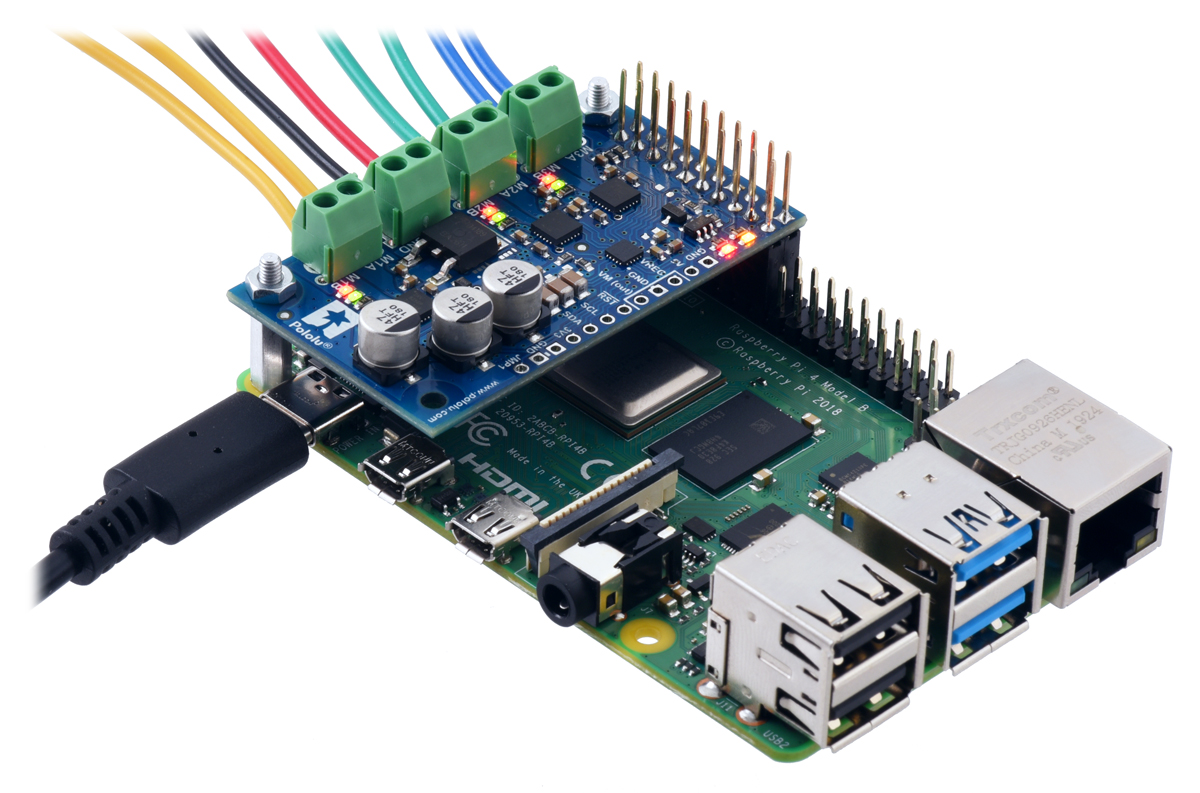
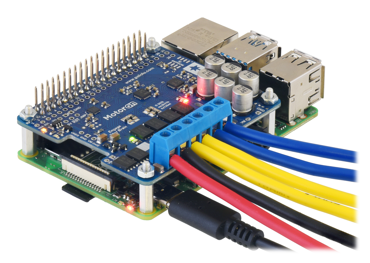
The Motoron M3H256 is designed to be plugged into pins 1 through 20 of a Raspberry Pi using female headers. The Motoron M2H is designed to be plugged into the 40-pin connector of a Raspberry Pi using female headers.
Plugging the Motoron into a controller this way connects the GND, SDA, and SCL pins of both boards, allowing the controller to communicate with the Motoron via I²C. It also powers the Motoron’s microcontroller by connecting the Raspberry Pi’s 3V3 pin to the Motoron’s logic voltage.
The Motoron does not need to be connected directly to the Raspberry Pi: it can be connected through another board (including other Motoron boards) as long as those boards pass the GND, SCL, SDA, and logic voltage connections through.
You can also connect the Motoron to a controller board that has a different shape as long as you make the same connections. The Motoron’s GND, SCL, and SDA pins should be connected to the corresponding pins on the controller board, and the Motoron’s logic voltage (labeled IOREF or 3V3 depending on which type of Motoron you have) should be connected to the logic voltage supply of the controller board (the allowable logic voltage range can be found in the specifications for your particular Motoron).
 |
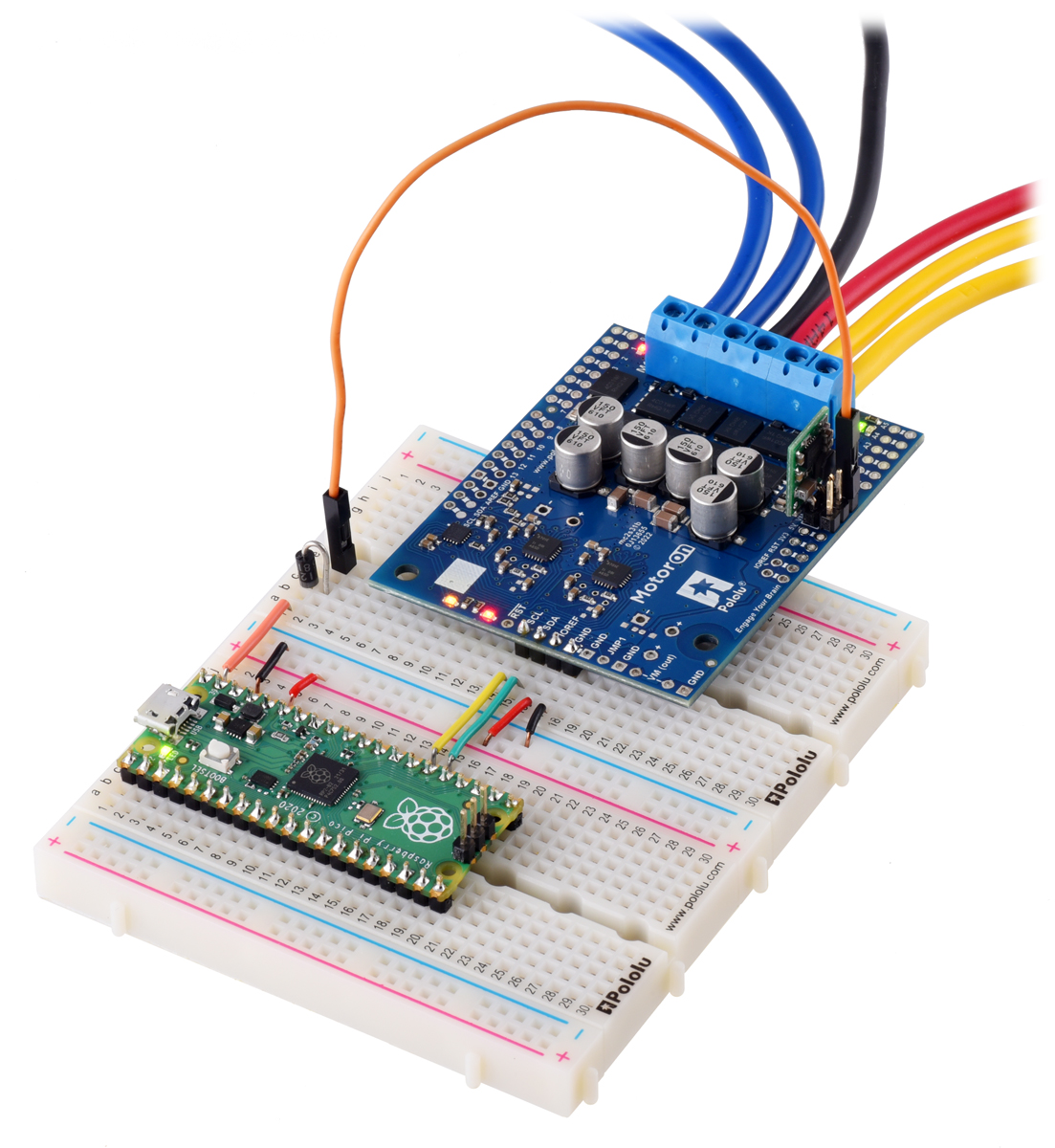
An Arduino Micro on a breadboard using a Motoron M3H256 to control three motors. |
|---|
After you have connected one Motoron to a controller, you can connect other Motorons to the same controller simply by stacking them above or below the first one.
Once you make the GND and logic power connections and turn on the logic power, you should see the Motoron’s yellow LED blink. The red LED will also turn on unless something is communicating with the Motoron and causing it to turn the LED off.
If you are planning to stack multiple Motoron M2H controllers, note that the procedure for setting their I²C addresses (as documented in Section 3.4) requires access to the GND and JMP1 pins, but those pins are in the middle of the board. Therefore, we recommend connecting and setting up one Motoron at a time before connecting the next one.
Powering the Raspberry Pi
By default, the Motoron does not supply power to the Raspberry Pi, so you will need to power your Raspberry Pi separately. However, there are options for powering the Raspberry Pi, as documented in Section 4.4 for the M3H550/M3H256 and Section 4.6 for the M2H controllers.
3.3. Enabling I²C on the Raspberry Pi
This section explains how to enable the correct I²C bus on your Raspberry Pi, make sure that your user has permission to access it, and test your setup.
The Motoron is designed to connect to the I2C1 bus on the Raspberry Pi, which uses GPIO pin 2 for SDA and GPIO pin 3 for SCL. If you are using Raspberry Pi OS, this bus is represented by /dev/i2c-1: that is the name of the device node that programs on your Raspberry Pi will open in order to communicate with the Motoron or any other targets on the bus.
Try typing ls /dev/i2c* to list your system’s available I²C busses. If /dev/i2c-1 is not in the list then you should run sudo raspi-config nonint do_i2c 0 to enable it. You must reboot your Raspberry Pi for this change to take effect.
We recommend adding your user to the i2c group so you can access the Motoron and other I²C devices without using sudo. Run the groups command to see what groups your user belongs to. If i2c is not in the list, then you should add your user to it by running sudo usermod -a -G i2c $(whoami), logging out, and then logging in again.
After you have enabled I²C and connected your Motoron to your Raspberry Pi’s I²C bus, run i2cdetect -y 1. If everything is set up correctly, you should see output like this:
     0  1  2  3  4  5  6  7  8  9  a  b  c  d  e  f
00:                         -- -- -- -- -- -- -- --
10: 10 -- -- -- -- -- -- -- -- -- -- -- -- -- -- --
20: -- -- -- -- -- -- -- -- -- -- -- -- -- -- -- --
30: -- -- -- -- -- -- -- -- -- -- -- -- -- -- -- --
40: -- -- -- -- -- -- -- -- -- -- -- -- -- -- -- --
50: -- -- -- -- -- -- -- -- -- -- -- -- -- -- -- --
60: -- -- -- -- -- -- -- -- -- -- -- -- -- -- -- --
70: -- -- -- -- -- -- -- --
This output means that the Raspberry Pi detected a device at address 16 (0x10 in hex), which is the default I²C address used by the Motoron.
3.4. Setting I²C addresses with a Raspberry Pi
If you have one Motoron and it is the only I²C target device in your system, there is no need to change the Motoron’s I²C address and you can skip this section.
Each device on an I²C bus should have a unique address so that you can communicate with the device without interfering with other devices on the bus. By default, the Motoron uses I²C address 16, so if you have connected two or more Motorons to your bus, or you have another device that uses address 16, you will need to change the I²C addresses of one or more Motorons.
If you need to change your Motoron’s I²C address, the recommended procedure for setting the I²C address of one or more Motorons that are connected to the I²C bus of your Raspberry Pi is:
- Ensure that the JMP1 pin on each Motoron is not connected to anything.
- Download the Motoron Motor Controller Python library, and install its dependencies, as described in the “Getting started” section of its README file.
- In a Terminal, use
cdto navigate into the directory holding the library and its examples. - Run
./i2c_set_addresses_example.py. This utility will print some information and then prompt you for a command. - Perform a scan of the I²C bus by typing “s” and pressing Enter. You should get output that looks like this:
Scanning for I2C devices…
Found device at address 0
Found device at address 16
Done.
The scan detects that a device on the bus is responding to address 16 because that is the Motoron’s default address. It also detects a device on address 0 because that is the I²C general call address and all Motorons respond to it by default, in addition to the normal address. We will use address 0 to send commands in later steps, so if the scan does not detect any devices on address 0, those steps will probably fail. - Warning: If you have devices on your I²C bus that are not Motorons, the steps below could cause undesired behavior by sending commands to them that are intended for the Motorons. You might consider removing those devices from your bus temporarily.
- Connect the JMP1 pin of one Motoron to GND. If you have not soldered headers to the JMP1 pin and its adjacent GND pin, you can connect those two pins together using a wire, test clip, or with a shorting block attached to a 1×2 male header. Connecting JMP1 to GND is how we select which Motoron’s address will be changed in the next step. Only one Motoron at a time should have its JMP1 pin connected to GND.
- Set the address of the selected Motoron by typing “a”, followed by the address (in decimal), and then pressing Enter. We recommend picking an address between 8 and 119 that is not in use by any other devices on your bus (numbers outside that range could work too, but they are reserved for other uses by the I²C specification). For example, type “a17” to set the address of the Motoron to 17. Alternatively, you can just send “a” by itself in order to have the program automatically pick an address for you, starting at 17 and skipping addresses that are already in use on the bus.
This sends a “Write EEPROM” command to all of the Motorons using address 0, but the command will only have an effect on the one Motoron whose JMP1 line is low. That Motoron will record the address in its non-volatile EEPROM memory, but will not start using it yet. - Disconnect the JMP1 pin from GND.
- Repeat the last three steps for every Motoron whose address you wish to change.
- Type “r” to make the new addresses take effect. This sends a “Reset” command to all of the Motorons using address 0. Alternatively, you can power cycle the system or use the RST pin to reset the Motorons.
- Perform another scan of the I²C bus by typing “s”. Check that a device is now found on each of the addresses that you assigned.
- Please note that most of the example code we provide is configured to use address 16. If you have assigned a different address to your Motoron, you will need to configure any code you run to use that same address. For example, when using the Python library, write
mc = motoron.MotoronI2C(address=17)to create a MotoronI2C object that uses address 17.
3.5. Setting I²C addresses with an Arduino
If you have one Motoron and it is the only I²C target device in your system, there is no need to change the Motoron’s I²C address and you can skip this section.
Each device on an I²C bus should have a unique address so that you can communicate with the device without interfering with other devices on the bus. By default, the Motoron uses I²C address 16, so if you have connected two or more Motorons to your bus, or you have another device that uses address 16, you will need to change the I²C addresses of one or more Motorons.
If you need to change your Motoron’s I2C address, the recommended procedure for setting the I²C address of one or more Motorons that are connected to the I²C bus of your Arduino is:
- Ensure that the JMP1 pin on each Motoron is not connected to anything.
- Install the Motoron Arduino library using the Arduino library manager. You can open the Library Manager from the “Tools” menu by selecting “Manage Libraries…”. If necessary, see the library’s README for more information about how to install it.
- Upload the I2CSetAddresses example to your Arduino. If the Motoron library is installed properly, you can find this example under Files > Examples > Motoron > I2CSetAddresses.
- Open the Arduino IDE’s Serial Monitor, which you can find in the “Tools” menu.
- Perform a scan of the I²C bus by typing “s” in the box at the top of the Serial Monitor and pressing Enter. You should get output that looks something like this:
Scanning for I2C devices…
Found device at address 0
Found device at address 16
Done.
The scan detects that a device on the bus is responding to address 16 because that is the Motoron’s default address. It also detects a device on address 0 because that is the I²C general call address and all Motorons respond to it by default, in addition to the normal address. We will use address 0 to send commands in later steps, so if the scan does not detect any devices on address 0, those steps will probably fail. - Warning: If you have devices on your I²C bus that are not Motorons, the steps below could cause undesired behavior by sending commands to them that are intended for the Motorons. You might consider removing those devices from your bus temporarily.
- Connect the JMP1 pin of one Motoron to GND. If you have not soldered headers to the JMP1 pin and its adjacent GND pin, you can connect those two pins together using a wire, test clip, or with a shorting block attached to a 1×2 male header. Connecting JMP1 to GND is how we select which Motoron’s address will be changed in the next step. Only one Motoron at a time should have its JMP1 pin connected to GND.
- Set the address of the selected Motoron by typing “a” in the box at the top of the Serial Monitor, followed by the address (in decimal), and pressing Enter. We recommend picking an address between 8 and 119 that is not in use by any other devices on your bus (numbers outside that range could work too, but they are reserved for other uses by the I²C specification). For example, type “a17” to set the address of the Motoron to 17. Alternatively, you can just send “a” by itself in order to have the sketch automatically pick an address for you, starting at 17 and skipping addresses that are already in use on the bus.
This sends a “Write EEPROM” command to all of the Motorons using address 0, but the command will only have an effect on the one Motoron whose JMP1 line is low. That Motoron will record the address in its non-volatile EEPROM memory, but will not start using it yet. - Disconnect the JMP1 pin from GND.
- Repeat the last three steps for every Motoron whose address you wish to change.
- Send “r” using the Serial Monitor to make the new addresses take effect. This sends a “Reset” command to all of the Motorons using address 0. Alternatively, you can power cycle the system or use the RST pin to reset the Motorons.
- Perform another scan of the I²C bus by sending “s”. Check that a device is now found on each of the addresses that you assigned.
- Please note that most of the example code we provide is configured to use address 16. If you have assigned a different address to your Motoron, you will need to configure any code you run to use that same address. For example, when using the Arduino library, write
MotoronI2C mc(17);to create a MotoronI2C object that uses address 17.
3.6. Changing serial settings with an Arduino
The Motoron’s default settings are sufficient for most applications consisting of one Motoron and one serial controller. If you do not have a specific reason to change a setting, you can skip this section.
Each Motoron with a UART serial interface has several settings for its serial interface that are stored in its non-volatile EEPROM memory and documented in Section 7. If you want to independently control multiple Motoron controllers from a single serial transmit line, you will need to assign a unique device number to each device using the procedure below. Another common reason to use the procedure below is if you want to use a baud rate other than the default rate of 115200 bps (bits per second).
If you need to change the settings in the EEPROM of a Motoron with a UART serial interface, the recommended procedure is:
- Connect a single Motoron to an Arduino or Arduino-compatible controller so that it can receive serial commands and send serial responses back to the Arduino. If you are not sure how to do this, refer to the Motoron library’s README.
- To successfully follow this procedure, you will need to know what baud rate your Motoron is using. It also helps if you know whether it is configured to use 7-bit responses and whether it is configured to use 14-bit device numbers. If you are not sure about the values the Motoron is currently using for any of those serial settings, then power cycle it (or reset it) while its JMP1 pin is shorted to GND. This causes the Motoron to use 9600 baud, 8-bit responses, and 7-bit device numbers until the next time it is reset.
- Install the Motoron Arduino library using the Arduino library manager. You can open the Library Manager from the “Tools” menu by selecting “Manage Libraries…”. If necessary, see the library’s README for more information about how to install it.
- Open the SerialSetup example. If the Motoron library is installed properly, you can find this example under Files > Examples > Motoron > SerialSetup.
- Find the line near the top of the code that defines
assignBaudRateand other parameters. If you want your Motorons to be configured to use a baud rate other than 115200 bps, or if you want them to use non-default values for any of the other settings defined in this area of the code, then you should change the definitions there to match what you want. - Upload the sketch to your Arduino.
- Open the Arduino IDE’s Serial Monitor, which you can find in the “Tools” menu. The top of the serial monitor contains a box where you can type commands and send them to the Arduino by pressing Enter.
- If your Motoron is currently using a baud rate other than the default of 115200 bps, use the Serial Monitor to send “b” followed by the baud rate in decimal (for example, “b9600”). This configures the Arduino to use the same baud rate so the Arduino can communicate with the Motoron.
- If your Motoron is currently using 7-bit responses or 14-bit device numbers, you should change the sketch to use the same settings so the sketch can detect the Motoron in the next step. To do this, type “o” and press Enter until the sketch reports the correct settings.
- To check your connections and configuration, send “i”. You should get output that looks something like this:
Identifying Motoron controllers (115200 baud, 7-bit device number, 8-bit responses)…
 16: product=0x00CF version=1.02 JMP1=off EEPROM=10 00 00 00 00 8B 00 00
Done.
This particular output shows that a Motoron M2U256 with device number 16 was detected and its EEPROM still contains factory settings. Note that the “i” command can take several minutes if you are using 14-bit device numbers, because the code checks each device number, one at a time. - Connect the JMP1 pin of the Motoron to GND. If you do not do this, the Motoron will ignore all commands that write to its EEPROM. This connection does not have to last for long, so it is OK to just hold it in place with your hand.
- Type “a” followed by the device number you want to assign to the Motoron, and optionally followed by the alternative device number you want to assign. This will write to the Motoron’s EEPROM, setting its device number, setting (or disabling) its alternative device number, and applying all the hardcoded settings that you set up step 5. For example send “a 17” to assign device number 17 and disable the alternative device number.
- Disconnect the JMP1 pin from GND.
- Send “r” using the Serial Monitor to reset the Motoron and make the new settings take effect. Alternatively you can power cycle the Motoron or reset it with its reset pin.
- To make sure the steps above worked and the Motoron is using the expected settings, you might want to send the “k” command followed by the “i” command. The “k” command tells the sketch to use the hardcoded serial settings that are being written to the Motorons, and “i” is the command to identify connected Motorons (as we already used above).
- Please note that most of the example code we provide is configured to use 115200 bps, use the Compact protocol (so all devices respond to the commands regardless of their device number), and use default values for all of the Motoron’s serial settings. If you change the serial settings of your Motoron, you will most likely need to configure your code to use the same settings. The documentation of the Motoron Arduino library (and in particular the MotoronSerial class) has information about the functions you can call to do that. The baud rate your code uses is not controlled by the Motoron library: it is controlled by the argument you pass when calling
begin()on the serial port object.
3.7. Writing code
This section documents what you need to know to get started writing code to control the Motoron.
To control the Motoron, you need to send commands to it using its I²C or UART serial interface (whichever one it has). The commands are sequences of bytes (8-bit numbers from 0 to 255) and some of them generate responses which are also sequences of bytes. The details of what commands are supported and how to encode them in bytes are documented in Section 3.7. The details of the Motoron’s I²C interface are documented in Section 6, and the details of its UART serial interface are documented in Section 7. Numbers prefixed with “0x” here are written in hexadecimal notation (base 16), and they are written with their most significant digits first, just like regular decimal numbers.
Arduino library and examples
If you are controlling the Motoron from an Arduino or Arduino-compatible board, we recommend that you install our Motoron Arduino library and use one of the examples that comes with it as a starting point for your code. The library comes with these beginner-friendly examples, which you can find in the Arduino IDE under Files > Examples > Motoron.
- I2CSimple and SerialSimple: Show how to control the Motoron in the simplest way.
- I2CCareful and SerialCareful: Show how to shut down the motors whenever any problems are detected.
- I2CRobust and SerialRobust: Show how to ignore or automatically recover from problems as much as possible.
Each of these examples just controls one Motoron. If you are using multiple Motorons, you can create an additional MotoronI2C or MotoronSerial object for each controller, and pass the device number (address) of each Motoron to the constructor for each object. This can be done for any of the examples listed above, and the library comes with a examples named I2CSimpleMulti and SerialSimpleMulti which show how to control multiple Motorons this way.
Python library and examples
If you are controlling the Motoron from Python or MicroPython, you might consider downloading our Motoron Python library and using one of the examples that comes with it as a starting point for your code. The Python library was designed to have the same features and behave nearly the same as the Arduino library. However, one major difference is that it generally throws an exception whenever there is a communication error, whereas the Arduino library only reports errors via its getLastError() method.
Like the Arduino library, the Python library comes with these beginner-friendly examples:
- *_simple_example.py: Show how to control the Motoron in the simplest way.
- *_careful_example.py: Show how to shut down the motors whenever any problems are detected.
- *_robust_example.py: Show how to ignore or automatically recover from problems as much as possible.
Each of these examples just controls one Motoron. If you are using multiple Motorons, you can create an additional MotoronI2C or MotoronSerial object for each controller, and pass the device number (address) of each Motoron to the constructor for each object. This can be done for any of the examples listed above, and the library comes with a examples named *_multi_example.py which show how to control multiple Motorons this way.
The library also comes with examples named *_simple_no_library_example.py which are equivalent to the corresponding simple examples, but do not use the Motoron library. These examples are meant to be used as a reference for people trying to get started with the Motoron from a different programming environment, since it is easier to see exactly what bytes are being sent.
Initialization sequence
This is a sequence of commands you can run near the beginning of your code to help you get started with controlling the Motoron.
Description: Reinitialize
Bytes: 0x96 0x74
This command resets the Motoron to its default state. We recommend doing this when starting up to ensure that the behavior of your system will only depend on the code you are currently running, instead of being affected by settings that you might have set previously in an old version of your code. The bytes shown above are the command byte for the “Reinitialize” command followed by a cyclic redundancy check (CRC) byte.
Description: Disable CRC
Bytes: 0x8B 0x04 0x7B 0x43
This command disables the cyclic redundancy check (CRC) feature of the Motoron (documented in Section 11). The CRC feature is enabled by default to make the Motoron less likely to execute incorrect commands when there are communication problems. Disabling CRC makes it easier to get started writing code for the Motoron because you do not have to implement the CRC computation or append CRC bytes to each command you send. Once you have gotten your system to work, you might consider implementing CRC and removing this command to make things more robust. This is an example of the more general “Set protocol options” command, and the last byte shown above is a CRC byte.
Description: Clear reset flag
Bytes: 0xA9 0x00 0x04
This command clears (sets to 0) a bit in the Motoron called the “Reset flag”. This flag gets set to 1 after the Motoron powers on or experiences a reset, and with the default configuration it is considered to be an error, so it prevents the motors from running.This is an example of the more general “Clear latched status flags” command, and there is no CRC byte appended because we disabled the CRC feature above.
The reset flag exists to help prevent running motors with incorrect settings. In case the Motoron itself gets reset while your system is running, the Reset flag will be set and the motors will not run.
Initialization sequence (with CRC)
This is similar to the initialization sequence above, except it leaves CRC enabled.
Description: Reinitialize
Bytes: 0x94 0x74
Description: Clear reset flag
Bytes: 0xA9 0x00 0x04
The bytes at the end of each command are CRC bytes. Instead of hard coding those bytes, you should be able to calculate each one by applying the CRC algorithm to the command and data bytes immediately before it.
Command timeout
By default, the Motoron will turn off its motors if it has not received a valid command in the last 1.5 seconds. The details of the command timeout feature are documented in Section 8. This means that the motors will stop running if your microcontroller crashes, goes into programming/bootloader mode, or stops running your motor control code for any other reason. You can send a “Set variable” command to configure the timeout period or disable the feature altogether. Change the “Command timeout” variable if you want to change the amount of time it takes for the Motoron to time out, or change the “Error mask” variable if you want to disable the command timeout. The “Set variable” command and all other commands are documented in Section 9.
Current limit
The Motoron M2S and M2H controllers have configurable hardware current limiting and the default value of the current limit is generally lower than what the controller is capable of, so you might need to set the current limit to get the desired performance of your system. However, note that the current limit should be set carefully because these high-power controllers do not have meaningful over-temperature protection. For more information see the “Current limit” variable in Section 8 and see the I2CCurrentSenseCalibrate example that comes with the Arduino library.
Motion parameters
You can send a “Set variable” command (documented in Section 9) to configure how the motors move and other settings. In particular, you can set acceleration and deceleration limits for each motor and each direction of motion, which helps to reduce sudden current spikes or jerky motions.
The Motoron only stores a few settings in its non-volatile EEPROM memory. Most settings, including the motion parameters and command timeout, get reset to their default values whenever the Motoron powers on, resets, or receives a “Reinitialize” command.
Motor control
Once you have taken care of the initialization and configuration described above, you are ready to run some motors! See the “Set speed” and “Set all speeds” commands in Section 9.
4. Pinout
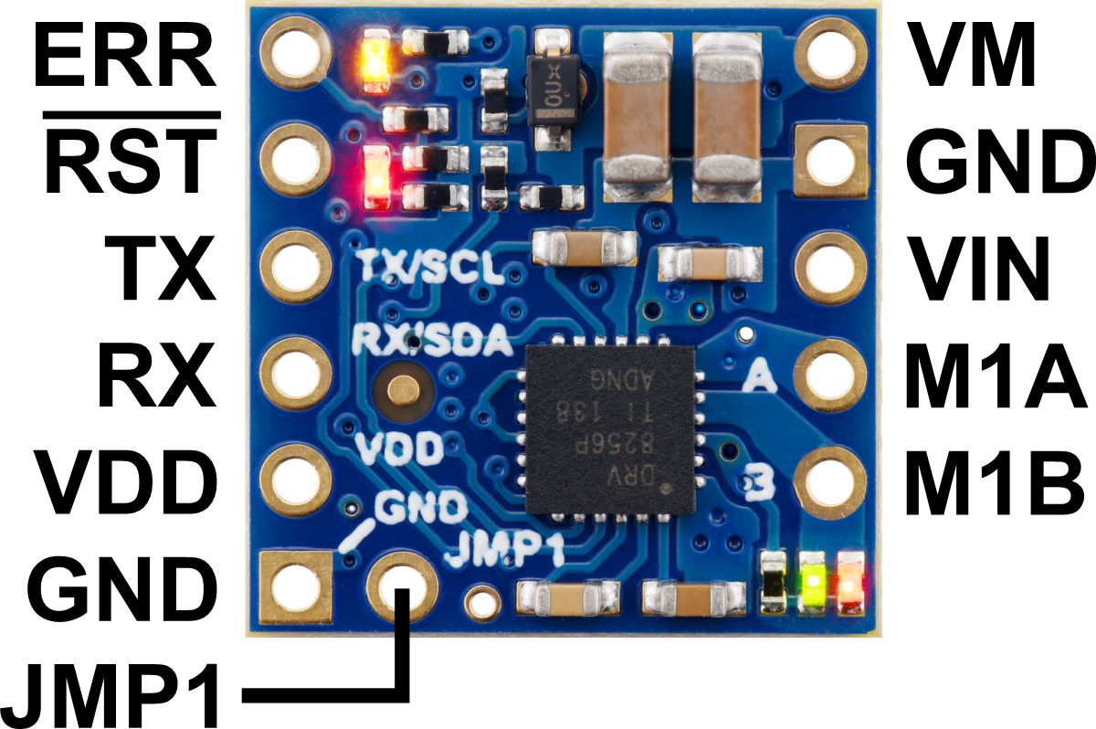
4.1. Motoron M1T550, M2T550, M1T256 and M2T256 pinout
|
|
||||
|
|
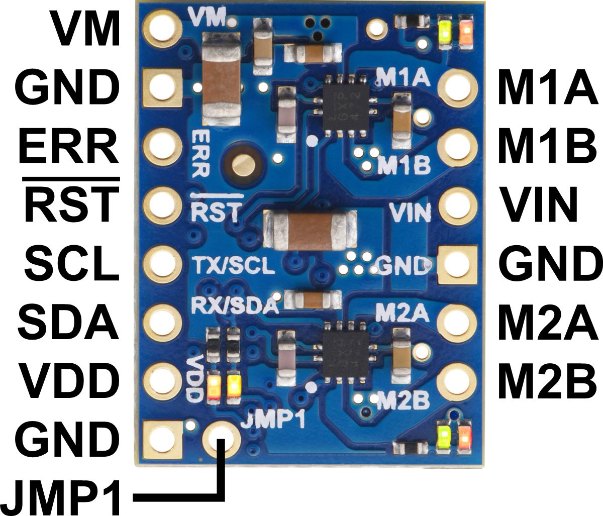
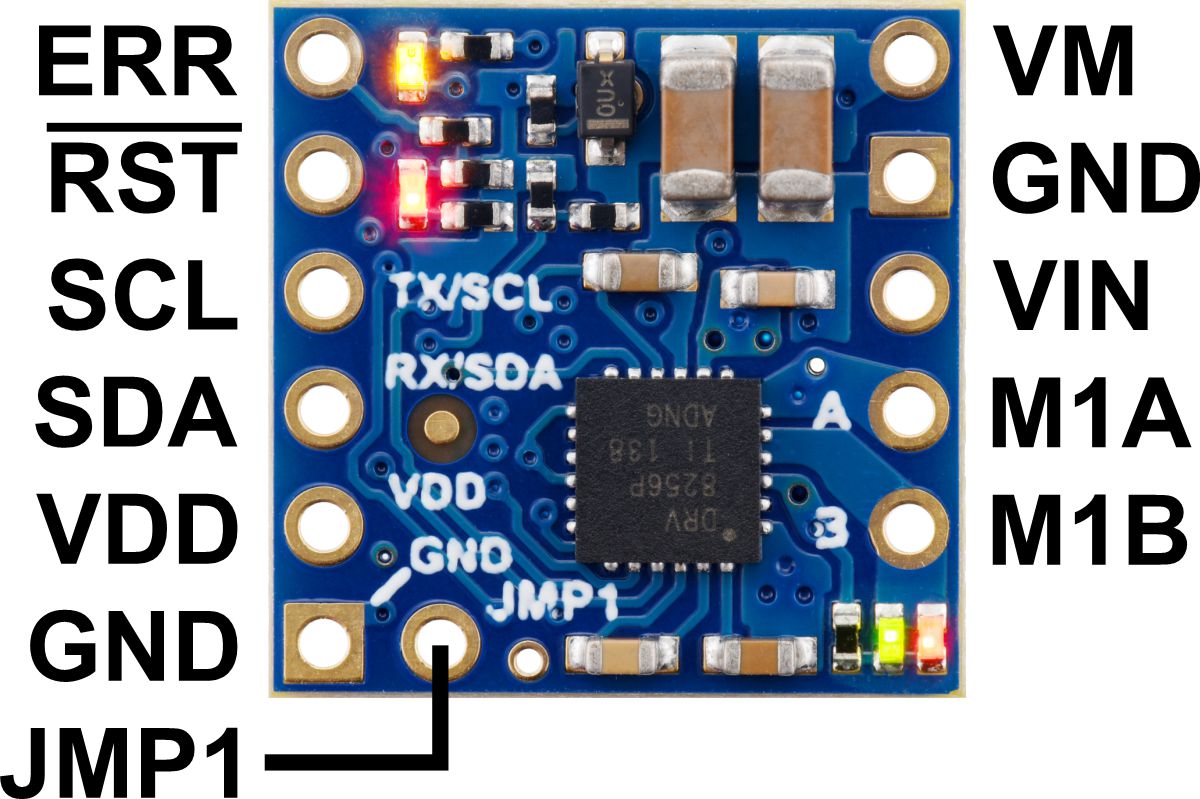
The diagrams above identify the control and power pins on the Motoron M1T550, M2T550, M1T256 and M2T256. Section 3.2.1 explains how to connect motor power, motors, and a microcontroller.
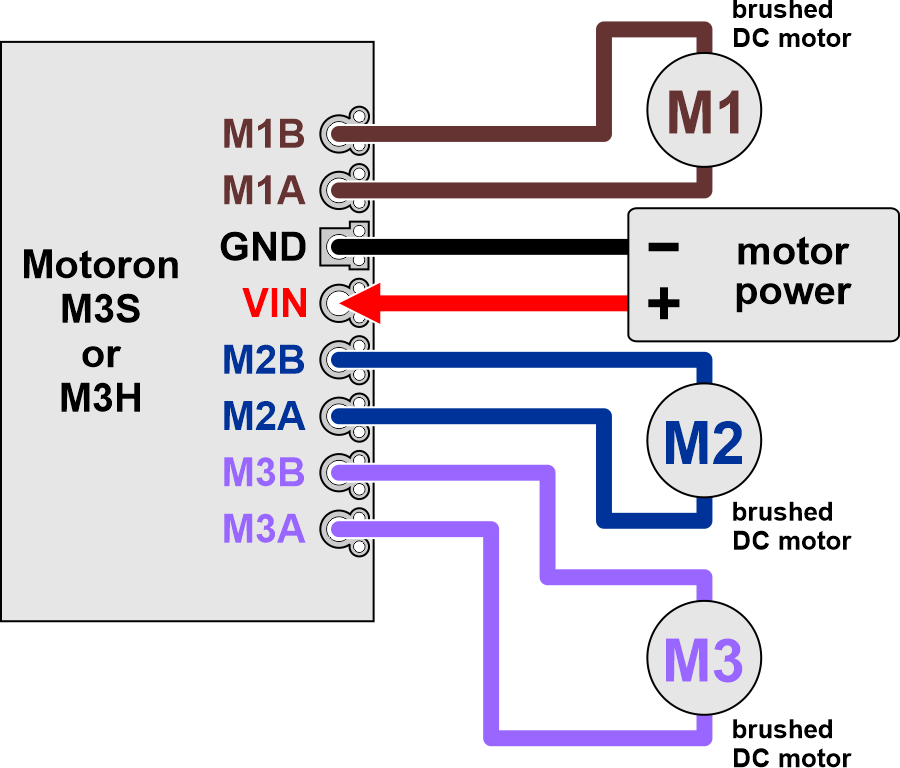
The motor power supply should be connected to the VIN pin and adjacent GND pin, and a motor can be connected to each pair of MxA and MxB pins (e.g. M1A and M1B). For more information on choosing a power supply and motors, see Section 3.1.
The Motoron’s logic is powered from the VDD pin, and it is controlled via I²C through the SCL and SDA pins (see Section 6). Additional GND pins provide a common ground reference between the Motoron and device controlling it.
The VM pin provides access to the reverse-protected motor supply voltage.
The ERR pin drives high when the red LED is on, which usually indicates an error as described in Section 5. The ERR pin is protected by a 220Ω series resistor. When the red LED is not on, the ERR pin is pulled down weakly.
The RST pin can be driven low to reset the Motoron; see Section 12 for more details.
The JMP1 pin can be shorted to the adjacent GND pin to allow the Motoron’s I²C address to be changed, as detailed in Section 3.5. Also, shorting JMP1 to GND at startup causes the Motoron to ignore the address configured in EEPROM and use 15 as its I²C address instead.
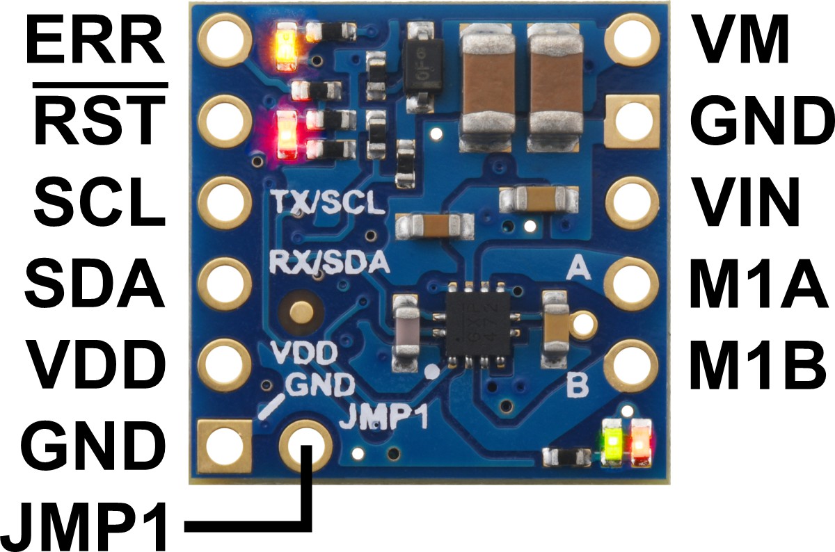
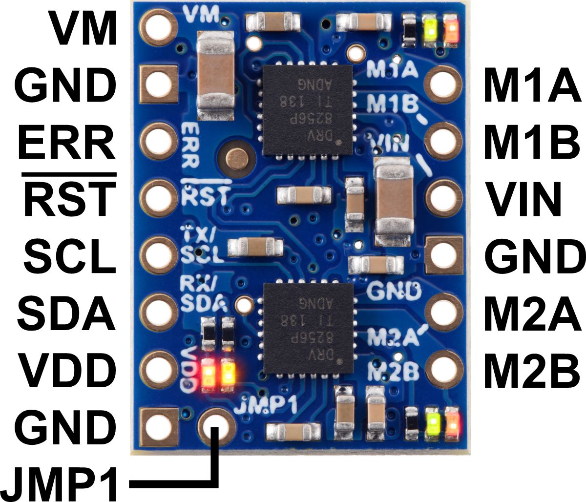
4.2. Motoron M1U550, M2U550, M1U256 and M2U256 pinout
|
|
||||
|
|
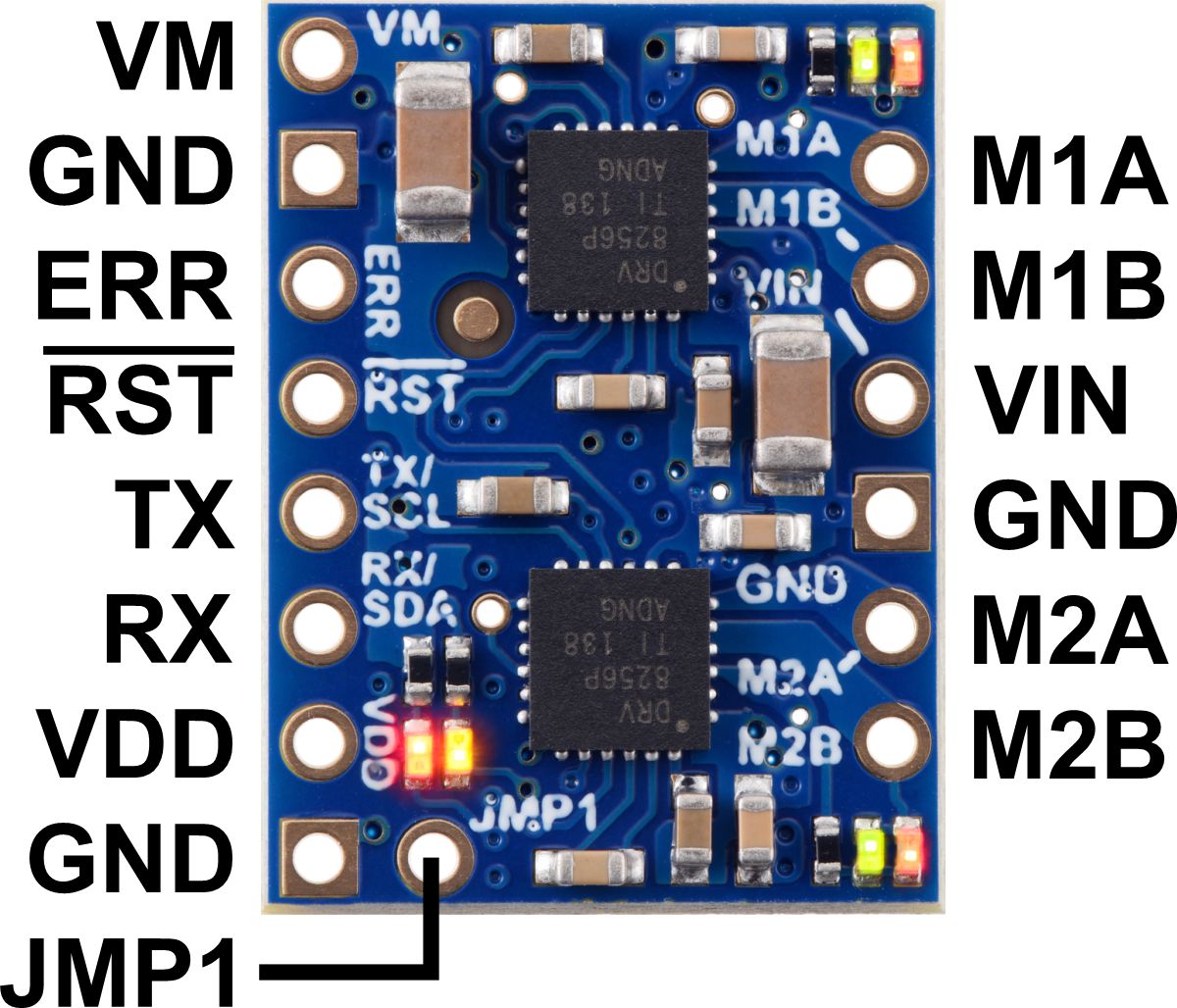
The diagrams above identify the control and power pins on the Motoron M1U550, M2U550, M1U256 and M2U256. Section 3.2.2 explains how to connect motor power, motors, and a microcontroller.
The motor power supply should be connected to the VIN pin and adjacent GND pin, and a motor can be connected to each pair of MxA and MxB pins (e.g. M1A and M1B). For more information on choosing a power supply and motors, see Section 3.1.
The Motoron’s logic is powered from the VDD pin, and it is controlled via UART serial through the TX and RX pins (see Section 7). Additional GND pins provide a common ground reference between the Motoron and device controlling it.
The VM pin provides access to the reverse-protected motor supply voltage.
The ERR pin drives high when the red LED is on, which usually indicates an error as described in Section 5. The ERR pin is protected by a 220Ω series resistor. When the red LED is not on, the ERR pin is pulled down weakly.
The RST pin can be driven low to reset the Motoron; see Section 12 for more details.
The JMP1 pin can be shorted to the adjacent GND pin to allow the Motoron’s serial settings to be changed, as detailed in Section 3.6. Also, shorting JMP1 to GND at startup causes the Motoron to ignore the serial settings configured in EEPROM and use safe default settings instead (see Section 10).
4.3. Motoron M3S550 and M3S256 pinout
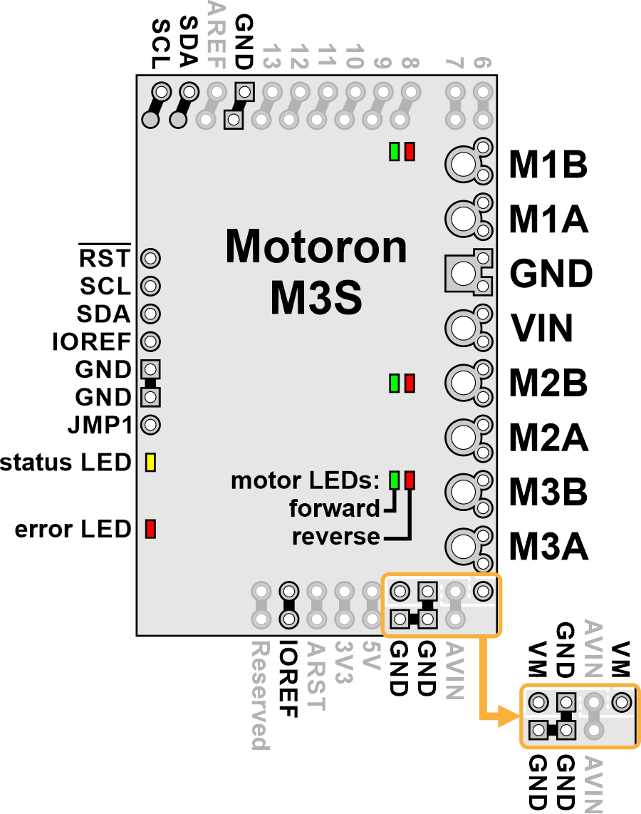 |
The diagram above identifies the control and power pins on the Motoron M3S550 and M3S256. Pins that are used by the motor controller are indicated in black, while pins that are not connected to anything by default are gray (these mostly serve as extra access points for the Arduino’s pins if the Motoron is plugged in as a shield). Section 3.2.3 explains how to connect motor power, motors, and a microcontroller.
The motor power supply should be connected to the VIN pin and adjacent GND pin, and a motor can be connected to each pair of MxA and MxB pins (e.g. M1A and M1B). For more information on choosing a power supply and motors, see Section 3.1.
The Motoron’s logic is powered from the Arduino by the IOREF pin. On the Motoron M3S256, the Motoron’s logic voltage (which powers its microcontroller) comes directly from IOREF. On the Motoron M3S550, the IOREF pin supplies power to a 3.3 LDO regulator, and the output of that regulator powers the Motoron’s microcontroller and is called the logic voltage.
The Motoron is controlled via I²C through the SCL and SDA pins (see Section 6). Additional GND pins provide a common ground reference between the Motoron and Arduino.
The JMP1 pin can be shorted to the adjacent GND pin to allow the Motoron’s I²C address to be changed, as detailed in Section 3.5. Also, shorting JMP1 to GND at startup causes the Motoron to ignore the address configured in EEPROM and use 15 as its I²C address instead.
The RST pin can be driven low to reset the Motoron; see Section 12 for more details.
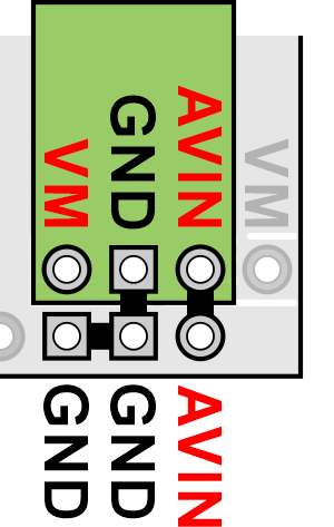
Powering the Arduino
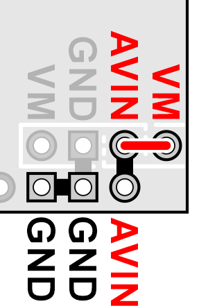
The VM pins near the lower right corner of the board provide access to the reverse-protected motor supply voltage. VM can optionally be used to power the Arduino’s VIN pin (AVIN) either directly or through a regulator.
If the voltage of your motor power supply is within the allowed input voltage range for your Arduino, then you can power the Arduino by connecting the Motoron’s AVIN pin to the nearby VM pin. Doing this supplies power to Arduino’s VIN pin (AVIN) from the reverse-protected motor supply voltage (VM).
Alternatively, you can power the Arduino through a voltage regulator. The Motoron M3S550 and M3S256 have VM, GND, and AVIN pins next to each other which are designed to be connected to a regulator. The regulator should be connected in the correct orientation so that the Motoron’s VM pin is connected to the regulator’s power input and the regulator’s power output is connected to AVIN. The motor power supply must be in the allowed input voltage range of the regulator, and the regulator must produce an output voltage that is within the allowed input voltage range of the Arduino. The regulator must also be able to supply enough current for the Arduino.
To avoid shorting two power outputs together, do not connect anything to the Arduino’s DC power jack while supplying power to AVIN through the Motoron.
|
|
4.4. Motoron M3H550 and M3H256 pinout
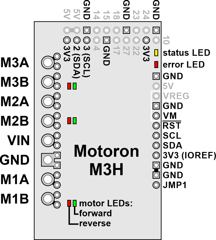 |
The diagram above identifies the control and power pins on the Motoron M3H550 and M3H256. Pins that are used by the motor controller are indicated in black, while pins that are not connected to anything by default are gray. Section 3.2.4 explains how to connect motor power, motors, and a microcontroller.
The motor power supply should be connected to the VIN pin and adjacent GND pin, and a motor can be connected to each pair of MxA and MxB pins (e.g. M1A and M1B). For more information on choosing a power supply and motors, see Section 3.1.
The Motoron’s logic is powered from the 3V3 pin, which connects to the pin of the same name on the Raspberry Pi. The Motoron is controlled via I²C through the SCL and SDA pins (see Section 6). Additional GND pins provide a common ground reference between the Motoron and the Raspberry Pi.
The JMP1 pin can be shorted to the adjacent GND pin to allow the Motoron’s I²C address to be changed, as detailed in Section 3.4. Also, shorting JMP1 to GND at startup causes the Motoron to ignore the address configured in EEPROM and use 15 as its I²C address instead.
The RST pin can be driven low to reset the Motoron; see Section 12 for more details.
The VM pin provides access to the reverse-protected motor supply voltage.
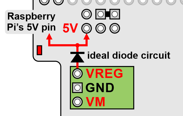
You can optionally power the Raspberry Pi by supplying 5 V to the VREG pin. To help achieve this, the Motoron M3H550 and M3H256 have adjacent VM, GND, and VREG pins which you can connect to a voltage regulator. The regulator should be connected in the correct orientation so that the Motoron’s VM pin connects to the regulator’s power input and the regulator’s power output connects to VREG. The motor power supply must be in the allowed input voltage range of the regulator, and the regulator must output 5 V (or something close enough to be tolerated by the Raspberry Pi). The regulator must also be able to supply enough current for the Raspberry Pi (e.g. 3 A for a Raspberry Pi 4). An ideal diode circuit on the Motoron prevents reverse current from flowing from the Raspberry Pi to the VREG pin if the Raspberry Pi is separately powered (for example, through its USB power receptacle). However, we do not recommend connecting external USB power to the Raspberry Pi while it is powered through the Motoron, since recent versions of the Raspberry Pi (including the 4 Model B and 3 Model B+) do not have a corresponding diode on their USB power input, so it is possible for the Motoron to backfeed a USB power adapter through the Raspberry Pi.
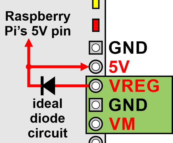 |
Powering the Raspberry Pi’s 5V pin from an external regulator connected to VM on a Motoron M3H550 or M3H256. |
|---|
The 5V pin connects to the pin of the same name on the Raspberry Pi. It is also the output of the ideal diode circuit.
4.5. Motoron M2S pinout
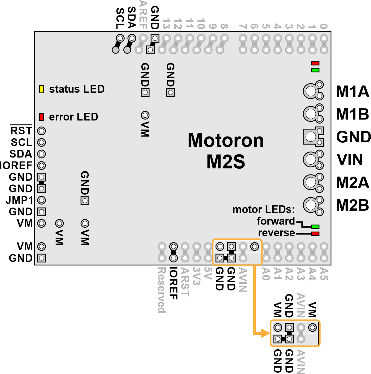 |
The diagram above identifies the control and power pins on the Motoron M2S shields (M2S18v18, M2S24v14, M2S18v20, and M2S24v16). Pins that are used by the motor controller are indicated in black, while pins that are not connected to anything by default are gray (these mostly serve as extra access points for the Arduino’s pins if the Motoron is plugged in as a shield). Section 3.2.3 explains how to connect motor power, motors, and a microcontroller.
The motor power supply should be connected to the VIN pin and adjacent GND pin, and a motor can be connected to each pair of MxA and MxB pins (e.g. M1A and M1B). For more information on choosing a power supply and motors, see Section 3.1.
The Motoron’s logic is powered from the Arduino by the IOREF pin, and it is controlled via I²C through the SCL and SDA pins (see Section 6). Additional GND pins provide a common ground reference between the Motoron and Arduino.
The JMP1 pin can be shorted to the adjacent GND pin to allow the Motoron’s I²C address to be changed, as detailed in Section 3.5. Also, shorting JMP1 to GND at startup causes the Motoron to ignore the address configured in EEPROM and use 15 as its I²C address instead.
The RST pin can be driven low to reset the Motoron; see Section 12 for more details.
Powering the Arduino
The VM pins near the lower right corner of the board provide access to the reverse-protected motor supply voltage. VM can optionally be used to power the Arduino’s VIN pin (AVIN) either directly or through a regulator.
If the voltage of your motor power supply is within the allowed input voltage range for your Arduino, then you can power the Arduino by connecting the Motoron’s AVIN pin to the nearby VM pin. Doing this supplies power to Arduino’s VIN pin (AVIN) from the reverse-protected motor supply voltage (VM).
Alternatively, you can power the Arduino through a voltage regulator. The shield has VM, GND, and AVIN pins next to each other which are designed to be connected to a regulator. The regulator should be connected in the correct orientation so that the Motoron’s VM pin is connected to the regulator’s power input and the regulator’s power output is connected to AVIN. The motor power supply must be in the allowed input voltage range of the regulator, and the regulator must produce an output voltage that is within the allowed input voltage range of the Arduino. The regulator must also be able to supply enough current for the Arduino.
To avoid shorting two power outputs together, do not connect anything to the Arduino’s DC power jack while supplying power to AVIN through the Motoron.
|
|
4.6. Motoron M2H pinout
 |
The diagram above identifies the control and power pins on the Motoron M2H controllers (M2H18v18, M2H24v14, M2H18v20, and M2H24v16). Pins that are used by the motor controller are indicated in black, while pins that are not connected to anything by default are gray. Section 3.2.4 explains how to connect motor power, motors, and a microcontroller.
The motor power supply should be connected to the VIN pin and adjacent GND pin, and a motor can be connected to each pair of MxA and MxB pins (e.g. M1A and M1B). For more information on choosing a power supply and motors, see Section 3.1.
The Motoron’s logic is powered from the 3V3 pin, which connects to the pin of the same name on the Raspberry Pi. The Motoron is controlled via I²C through the SCL and SDA pins (see Section 6). Additional GND pins provide a common ground reference between the Motoron and the Raspberry Pi.
The JMP1 pin can be shorted to the adjacent GND pin to allow the Motoron’s I²C address to be changed, as detailed in Section 3.4. Also, shorting JMP1 to GND at startup causes the Motoron to ignore the address configured in EEPROM and use 15 as its I²C address instead.
The RST pin can be driven low to reset the Motoron; see Section 12 for more details.
The VM pin provides access to the reverse-protected motor supply voltage.
You can optionally power the Raspberry Pi by supplying 5 V to the VREG pin. To help achieve this, the Motoron M2H has adjacent VM, GND, and VREG pins which you can connect to a voltage regulator. The regulator should be connected in the correct orientation so that the Motoron’s VM pin connects to the regulator’s power input and the regulator’s power output connects to VREG. The motor power supply must be in the allowed input voltage range of the regulator, and the regulator must output 5 V (or something close enough to be tolerated by the Raspberry Pi). The regulator must also be able to supply enough current for the Raspberry Pi (e.g. 3 A for a Raspberry Pi 4). An ideal diode circuit on the Motoron prevents reverse current from flowing from the Raspberry Pi to the VREG pin if the Raspberry Pi is separately powered (for example, through its USB power receptacle). However, we do not recommend connecting external USB power to the Raspberry Pi while it is powered through the Motoron, since recent versions of the Raspberry Pi (including the 4 Model B and 3 Model B+) do not have a corresponding diode on their USB power input, so it is possible for the Motoron to backfeed a USB power adapter through the Raspberry Pi.
 |
Powering the Raspberry Pi’s 5V pin from an external regulator connected to VM on a Motoron M2H. |
|---|
The 5V pin connects to the pin of the same name on the Raspberry Pi. It is also the output of the ideal diode circuit.
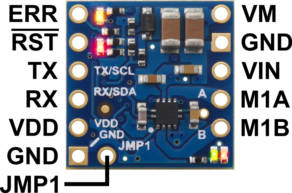
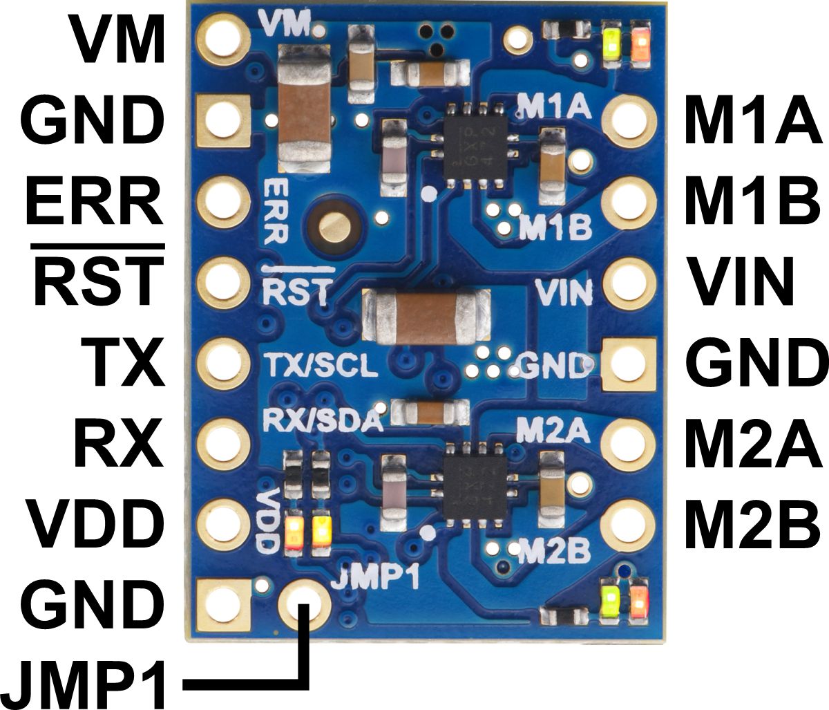
4.7. Motoron M3T453 pinout
 |
Pinout of the Motoron M3T453 Triple I²C Motor Controller with JST SH-Style Connectors. |
|---|
 |
Pinout of the Motoron M3T453 Triple I²C Motor Controller with 0.1″-Pitch Through-Holes. |
|---|
The diagrams above identify the control and power pins on the Motoron M3T453. Section 3.2.1 explains how to connect motor power, motors, and a microcontroller.
The motor power supply should be connected to the VIN pin and adjacent GND pin, and a motor can be connected to each pair of MxA and MxB pins (e.g. M1A and M1B). For more information on choosing a power supply and motors, see Section 3.1.
The Motoron’s logic is powered from the VDD pin, and it is controlled via I²C through the SCL and SDA pins (see Section 6). Additional GND pins provide a common ground reference between the Motoron and device controlling it.
The VM pin provides access to the reverse-protected motor supply voltage.
The ERR pin, which is only available on the version with 0.1"-pitch through-holes, drives high when the red LED is on, which usually indicates an error as described in Section 5. The ERR pin is protected by a 220Ω series resistor. When the red LED is not on, the ERR pin is pulled down weakly.
The RST pin can be driven low to reset the Motoron; see Section 12 for more details.
The JMP1 pin can be shorted to the adjacent GND pin to allow the Motoron’s I²C address to be changed, as detailed in Section 3.5. Also, shorting JMP1 to GND at startup causes the Motoron to ignore the address configured in EEPROM and use 15 as its I²C address instead.
5. LED feedback
The Motoron Motor Controller has several LEDs to indicate its status.
Status LEDs
On the edge of the board, opposite the motor output pins, there are two status LEDs.
The yellow status LED indicates reset events and shows when the motor outputs are enabled.
- During the first half second after the Motoron has powered up or its processor has been reset, the yellow LED blinks 4 times.
- Otherwise, if the Motoron motor outputs are enabled or the Motoron is trying to enable them, the yellow LED is on solid. This corresponds to the “Motor output enabled” bit in the “Status flags” variable, which is documented in Section 8.
- Otherwise, if the Reset bit in the “Status flags” variable is set and it is configured to be an error, the yellow LED blinks for 0.5 s once per second. This is the default state, and it generally indicates that communication has not been established.
- Otherwise, the yellow LED blinks briefly once per second.
The red error LED usually indicates hardware issues or errors that prevent the motors from running.
- If you have a Motoron with a UART serial interface and have enabled the “ERR is DE” option, the red LED will only turn on while the Motoron is transmitting a response on its TX line.
- Otherwise, the red LED will be on solid if a motor fault is happening, motor power has been lost, or if there is a firmware-level error stopping the motors from running. More specifically, the red LED will be on if any of the “Motor faulting”, “No power”, or “Error active” flags documented in Section 8 are 1.
- Otherwise the red LED will be off.
If the red LED is off, it does not necessarily mean that the VIN power voltage is high enough for the Motoron to drive motors.
Motor direction LEDs
On the side of the board with the motor output pins, each motor has two direction indicator LEDs.
The green direction LED indicates that the voltage on the MxA pin is high while the voltage on the MxB pin is low. This direction is called forward and corresponds to a positive speed numbers.
The red direction LED indicates that the voltage on the MxB pin is high while the voltage on the MxA pin is low. This direction is called reverse and corresponds to a negative speed numbers.
Both direction LEDs get brighter if the absolute value of the speed increases, or if the motor power supply (VIN) increases.
6. I²C interface
To control the Motoron M1T550, M2T550, M3S550, M3H550, M1T256, M2T256, M3S256, M3H256, M3T453, M2S, or M2H, you will need to use the Motoron’s I²C interface.
I²C is a specification for a bus that can be used to connect multiple devices. The bus uses two signal lines: SDA is the data line and is used to transmit and receive data, while SCL is the clock line is used to coordinate the flow of data. There are two types of devices that can connect to an I²C bus: a controller is a device that initiates transfers of data, generates clock signals, and terminates transfers, while a target is a device that is addressed by a controller. The Motoron acts only as a target.
I²C voltage levels
The voltages on the Motoron’s SDA and SCL lines must not exceed 6.5 V (they are 5 V tolerant). Each of these lines is pulled up with an on-board 10 kΩ pull-up resistor. On the Motoron shields for Arduino, the pull-ups connect to IOREF. On Motoron controllers for Raspberry Pi, the pull-ups connect to the 3V3 pin. On other Motorons the pull-ups connect to the VDD pin. For the signals on SDA and SCL to be read properly by the Motoron, the low level must be less than 30% of the Motoron’s logic voltage, and the high level must be more than 70% of the Motoron’s logic voltage.
I²C clock speed
The Motoron’s I²C interface supports clock speeds up to 400 kHz. It uses clock stretching to slow down the transfer of data when bytes are written faster than it can handle, or if a read transfer is started before data is available.
If your I²C controller does not support clock stretching properly, you can avoid clock stretching by limiting your write transfers to be at most 31 bytes long and delaying for 1 millisecond after each write transfer to give the Motoron time to process it.
I²C address
By default, the Motoron uses the 7-bit I²C address 16. This address is stored in the Motoron’s non-volatile EEPROM memory, and you can change it by sending a “Write EEPROM” command. If the JMP1 pin is shorted to GND at startup, the Motoron will ignore the address in EEPROM and use 15 as its I²C address instead. The Motoron determines what I²C address to use when it starts up, so any changes to the JMP1 pin or the EEPROM will not take effect until the next reset.
The Motoron also responds to the I²C general call address (0) in addition to its normal address by default. This allows you to send the same command to multiple Motoron targets simultaneously. The general call address is write-only; reading bytes from it is not supported. (However, if you send a command to the general call address that results in a response, you can read the response from an individual Motoron using its regular address.) You can use the “Set protocol options” command to disable the general call address, but it will become re-enabled the next time the Motoron is reset.
I²C protocol
There are two types of data transfers that can be initiated by an I²C controller: a write transfer writes some number of bytes to a target, and a read transfer reads some number of bytes from the target.
When you write bytes to the Motoron using write transfers, those bytes are interpreted as commands as described in Section 9. The Motoron does not care how the bytes are grouped into write transfers: you can send each command in its own transfer for simplicity, or send multiple commands together in a single transfer for extra efficiency. The Motoron acknowledges every byte written to it using I²C’s built-in acknowledgment mechanism, regardless of whether those bytes actually form valid commands.
Some Motoron commands generate responses. To read the response to a command, you can start a read transfer after writing the last byte of a command, before you have written any other bytes. (To ensure that responses do not get mixed up, the Motoron clears its stored response every time a new byte is written.) It is OK to skip reading a response if you do not need it, or to just read part of it. It is also OK to read the response using multiple read transfers.
If you read bytes via I²C at a time when there is no response data available, the Motoron will provide a value of 0xAA for each byte you read. This can happen if you read at the wrong time, or if you read too many bytes. Enabling CRC for responses (as described in Section 9) and checking the value of the CRC byte is a good way to detect if this is happening.
7. Serial interface
To control the Motoron M1U550, M2U550, M1U256 or M2U256, you will need to use the Motoron’s UART serial interface.
The RX and TX pins of the Motoron provide its serial interface. The Motoron’s RX pin is an input, and its TX pin is an output. The RX pin has a weak pull-up resistor, and each pin is protected by a 220Ω series resistor.
Serial voltage levels
The UART serial interface uses non-inverted TTL logic levels: a level of 0 V corresponds to a value of 0, and a level of VDD corresponds to a value of 1. The input signal on RX must be below 0.3×VDD to be recognized as low, and above 0.7×VDD to recognized as high. The voltage on RX must not exceed VDD by more than 0.3 V. Therefore, if the Motoron is running at 3.3 V, its RX pin is not 5 V tolerant.
Serial data format
The data format is 8 data bits, one stop bit, with no parity, which is often expressed as 8-N-1. The diagram below depicts a typical serial byte:
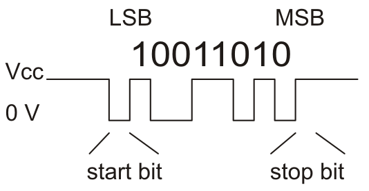 |
Diagram of a non-inverted TTL serial byte. |
|---|
Serial baud rate
The UART serial interface is asynchronous, meaning that the sender and receiver each independently time the serial bits. The sender and receiver must be configured to use the same baud rate, which is typically expressed in bits per second.
By default, the Motoron uses 115200 baud. The baud rate is stored in the Motoron’s non-volatile EEPROM memory, and you can change it by sending a “Write EEPROM” command. If the JMP1 pin is shorted to GND at startup, the Motoron will ignore the baud rate in EEPROM and use 9600 baud instead. The Motoron determines what baud rate to use when it starts up, so any changes to the JMP1 pin or the EEPROM will not take effect until the next reset.
The Motoron supports baud rates from 300 to 250000 bps. It is possible to configure the Motoron to use baud rates up to 1 Mbps, but there are two potential problems with high baud rates. First of all, if the Motoron receives a rapid stream of commands using a baud rate higher than 115200, there is a risk that the Motoron firmware might not process the commands fast enough and eventually start discarding data (this condition is called a software overrun and can be detected). Secondly, the Motoron can only generate baud rates of the form 16 Mbps divided by an integer, so baud rates faster than 115200 baud cannot always be accurately generated.
Serial command protocols
The Compact protocol is the simpler and more compact of the two protocols supported by the Motoron. It is the protocol you should use if the Motoron is the only device connected to your serial line. A compact protocol command consists of a command byte with its most-significant byte set followed by the data bytes needed for the command (if there are any), each of which has its most-significant bit cleared. The Command reference section documents the specific bytes you need to send for a compact protocol command. You also need to append a cyclic redundancy check byte at the end of the command unless you have disabled CRC for commands.
The Pololu protocol can be used in situations where you have multiple devices connected to your serial line. This protocol is compatible with the serial protocol used by our other serial motor and servo controllers. As such, you can daisy-chain a Motoron on a single serial line along with our other serial controllers (including additional serial Motorons) and use the Pololu protocol to send commands specifically to the designated Motoron without confusing other devices on the line. Any compact protocol command can be transformed into a Pololu protocol command using the following process: first, clear the most significant bit of the command byte (the first byte). For example, the command byte of a normal “Set speed” command is 0xD1, and it becomes 0x51 in the Pololu protocol. Next, insert at the beginning of the command a 0xAA byte followed by a byte between 0 and 127 that specifies the device number of the Motoron you want to address. Unless you have disabled CRC for commands, you need to append a CRC byte at the end of the command and it must be calculated over the entire Pololu protocol command, including the first two bytes.
The Motoron’s device number is 16 by default. The device number is stored in the Motoron’s non-volatile EEPROM memory, and you can change it by sending a “Write EEPROM” command. If the JMP1 pin is shorted to GND at startup, the Motoron will ignore the device number in EEPROM and use 15 instead. The Motoron determines what device number to use when it starts up, so any changes to the JMP1 pin or the EEPROM will not take effect until the next reset.
You do not need to configure the Motoron ahead of time to use a specific protocol: the Motoron will detect what protocol you are using from the first byte of your command.
The Motoron can be configured to respond to an alternative device number. If the alternative device number is enabled, the Motoron will respond to commands that are addressed to either the primary device number or the alternative device number. This can be useful if you want to assign your Motorons to groups and send a single command to all the Motorons in a group, while still being able to individually address each Motoron.
Communication option: 14-bit responses
The Motoron can be configured to use a 14-bit device number. With this option enabled, the device numbers can range from 0 to 16383, instead of the typical range of 0 to 127. After the 0xAA byte, you have to send two device number bytes, both of which are between 0 and 127: the first byte holds the lower 7 bits of the device number, while the second byte holds the upper 7 bits of the device number. The format of the “Multi-device error check” and “Multi-device write” commands also change when this option is enabled.
Communication option: 7-bit responses
In general, the data sent by the Motoron in response to serial commands is arbitrary binary data: the bytes can be anything from 0 to 255. The Motoron’s 7-bit responses option causes it to encode those responses in a format that only uses values from 0 to 127. This can be useful if you have wired your Motorons in such a way that the responses from one Motoron will be seen by another Motoron, and you do not want those responses to accidentally be interpreted as commands.
The 7-bit encoding performed by the Motoron works as follows. First, if the serial response is longer than 7 bytes, the Motoron truncates it to be exactly 7 bytes long, throwing away all the bytes after the first 7. This behavior might change in future firmware versions, so we recommend that you do not request more than 7 bytes from the Motoron if you have enabled 7-bit responses. Next, the Motoron sets the most-significant bit of each byte in the response to 0. The Motoron packs the former values of those most significant bits (MSbs) into a single byte and appends it to the response. The bits of that final byte are in the same order as the bytes they correspond to: the least significant bit corresponds to the first byte, while the next bit corresponds to the second byte, and so on. The Motoron does this conversion before it computes and appends the (optional) CRC byte for the response.
Communication option: ERR is DE
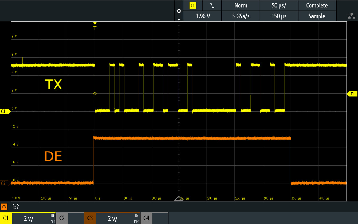 |
Oscilloscope trace showing the ERR/DE pin of the Motoron M2U256 driving high while its TX pin sends data. |
|---|
The Motoron’s ERR pin can be configured to act as a driver enable (DE) line. When the ERR is DE option is enabled, instead of indicating errors as described in Section 5, the ERR pin will drive high while the Motoron is transmitting serial data on its TX pin and drive low at other times. This feature is intended to be used in RS-485 systems where the ERR pin is connected to the driver enable (DE) pin of an RS-485 transceiver. The Motoron’s red LED is tied to the ERR pin, so its will briefly blink whenever the Motoron transmits a serial response.
Response delay
The Motoron’s Response delay setting specifies an additional delay that the Motoron will perform before sending a serial response. This can be useful in systems where another device is reading data from the Motoron and needs some time to switch from transmitting to receiving. The setting is 0 by default, and can be as large as 255 µs, with 1 µs resolution.
Configuring the UART serial interface
You can change the Motoron’s UART serial settings by following the instructions in Section 3.6. Alternatively, write your own code that use the “Write EEPROM” command documented in Section 9. The encoding of the serial settings in EEPROM is documented in Section 10.
8. Variable reference
The Motoron maintains a set of variables in RAM that contain information about its inputs, outputs, and status. The Motoron’s “Get variable” command allows you to read the variables, and there are other commands that allow you to set or modify the variables.
The variables are divided into two categories:
- General variables apply to all the motors, or the controller as a whole. The Motoron just stores one copy of each general variable.
- Motor-specific variables can be different for each motor. The Motoron stores a separate copy of the variable for each motor, and you must provide a motor number when accessing the variable.
This section lists all of the variables that the Motoron supports. In addition to the category, this section contains several pieces of information for each variable, if applicable:
- The Offset of each variable is its location among the variables in the same category. The offset is measured in bytes.
- The Type specifies how many bits the variable occupies, and says whether it is signed or unsigned.
- The Range specifies what values the variable can have.
- The Default specifies the value that the variable has when the controller starts up, before it has been modified.
- The Units specify the relationship between values of the variable and real-world quantities.
- The Data indicates how to interpret different possible values of the variable.
- The Command is the name of a command that can be used to set the variable.
- The Arduino library field shows the methods in the Arduino library that can be used to access the variable.
The term “bit 0” refers to the least significant bit of a variable (the bit that contributes a value of 1 to the variable when it is set). Accordingly, the other bits of a variable are numbered in order from least significant to most significant. All variables use little-endian byte ordering, meaning that the least-significant byte comes first.
List of variables
- Protocol options
- Status flags
- VIN voltage
- Command timeout
- Error response
- Error mask
- Jumper state
- UART faults
- PWM mode
- Target speed
- Target brake amount
- Current speed
- Buffered speed
- Max acceleration forward
- Max acceleration reverse
- Max deceleration forward
- Max deceleration reverse
- Starting speed forward
- Starting speed reverse
- Direction change delay forward
- Direction change delay reverse
- Current limit
- Current sense raw
- Current sense speed
- Current sense processed
- Current sense offset
- Current sense minimum divisor
Protocol options
| Category | general |
|---|---|
| Offset | 0 |
| Type | unsigned 8-bit |
| Data |
|
| Default | 7 (all options enabled) |
| Command | Set protocol options |
| Arduino library | void setProtocolOptions(uint8_t options)void enableCrc()void disableCrc()void enableCrcForCommands()void disableCrcForCommands()void enableCrcForResponses()void disableCrcForResponses()void enabeI2cGeneralCall()void disableI2cGeneralCall() |
This variable holds bits specifying which features of the Motoron’s command protocol are enabled. A bit value of 1 indicates that the corresponding feature is enabled. For more information about these features, see the documentation of the “Set protocol options” command in Section 9.
Status flags
| Category | general |
|---|---|
| Offset | 1 |
| Type | unsigned 16-bit |
| Default | 0x2200 (Reset, Error active) |
| Data |
|
| Command | Clear latched status flags Set latched status flags |
| Arduino library | uint16_t getStatusFlags()bool getProtocolErrorFlag()bool getCrcErrorFlag()bool getCommandTimeoutLatchedFlag()bool getMotorFaultLatchedFlag()bool getNoPowerLatchedFlag()bool getUARTErrorFlag()bool getResetFlag()bool getMotorFaultingFlag()bool getNoPowerFlag()bool getErrorActiveFlag()bool getMotorOutputEnabledFlag()bool getMotorDrivingFlag()void clearLatchedStatusFlags(uint16_t flags)void clearResetFlag()void setLatchedStatusFlags(uint16_t flags) |
There are several status flags that are latched, meaning that after they get set to 1, they stay set until they are cleared by a “Clear latched status flags” command. Most of these flags are also cleared by the Reinitialize command.
- The Protocol error flag indicates that the Motoron received an invalid byte in a command other than the CRC byte, as documented in Section 9.
- The CRC error flag indicates that CRC for commands was enabled and the Motoron received an incorrect CRC byte at the end of a command.
- The Command timeout latched flag indicates that the Motoron’s command timeout feature was activated because too much time has passed since it received a valid command. See the description of the Command timeout variable below for more information about this feature. This flag is the latched version of the “Command timeout” flag documented below.
- The Motor fault latched flag indicates that one or more of the motors experienced an error. This flag gets set to 1 whenever the “Motor faulting” flag below is 1, so see the documentation of that flag for more details.
- The No power latched flag indicates that the VIN voltage fell to a level that was definitely too low to run motors. This flag gets set to 1 whenever the “No power” flag documented below is 1, so see the documentation of that flag for more details.
- The UART error flag indicates that there was a problem preventing the Motoron from receiving serial data properly on its RX line, and some data could have been lost or corrupted. If this bit is set, you can read the UART faults variable to get more information about what specific error is happening. This bit is only implemented on Motorons with a UART serial interface.
- The Reset flag gets set to 1 when the Motoron powers on, or its processor is reset, or it receives a Reinitialize command.
There are several non-latched status flags which cannot be directly set or cleared.
- The Command timeout flag indicates that the Motoron’s command timeout feature is active because too much time has passed since it received a valid command. Every valid command clears this bit. See the description of the Command timeout variable below for more information about this feature.
- The Motor faulting flag is 1 if one or more of the motors is experiencing an error. This means that something is going wrong with the motor, and the outputs for it will be disabled until the problem is resolved. Due to hardware limitations, there is no way to tell which motor is experiencing the fault.
- For the Motoron M1T550, M1U550, M2T550, M2U550, M3S550, and M3H550, this flag is always 0. Under-voltage, over-current, and over-temperature faults will shut down the motor but they can not be detected using this bit.
- For the Motoron M1T256, M1U256, M2T256, M2U256, M3S256, and M3H256, a fault occurs if the VIN power drops below about 4.4 V and remains above about 3.4 V. A fault occurs if a motor current over 8 A or a temperature over 165 °C is measured. The over-current and over-temperature faults are latched, so the motor will not recover from those errors until you use the “Clear motor fault” command, command the motors to coast, or disconnect motor power. There are other hardware conditions that can cause temporary faults.
- For the Motoron M3T453, a fault occurs if the VIN power drops below about 3.8 V and remains above about 2.0 V. A fault occurs if a motor current over approximately 5.5 A or a temperature over 165 °C is measured. None of the faults are latched, so they will end when the condition causing them goes away.
- For the Motoron M2S and M2H controllers, a fault occurs if the VIN power drops below about 5.4 V and remains above about 3 V. Faults can also occur in response to various other internal conditions, but there is no over-temperature shutoff. None of the faults are latched, so they will end when the condition causing them goes away.
- The No power flag is 1 if the VIN voltage measurement indicates that the controller’s VIN voltage is definitely too low to run the motors. If this flag is 0, the VIN voltage might be sufficient.
- For the Motoron M1T550, M1U550, M2T550, M2U550, M3S550, and M3H550, this flag is 1 if and only if the VIN voltage measurement is less than 19. This corresponds to a VIN of 0.9 V if the Motoron’s logic voltage is 5 V, and 0.6 V if the Motoron’s logic voltage is 3.3 V.
- For the Motoron M1T256, M1U256, M2T256, M2U256, M3S256 and M3H256, this flag is 1 if and only if the VIN voltage measurement is less than 27. This corresponds to a VIN of 2.9 V if the Motoron’s logic voltage is 5 V, and 1.9 V if the logic voltage is 3.3 V.
- For the Motoron M3T453, this flag is 1 if and only if the VIN voltage measurement is less than 21. This corresponds to a VIN of 2.3 V if the Motoron’s logic voltage is 5 V and 1.5 V if the logic voltage is 3.3 V.
- For the Motoron M2S and M2H controllers, this flag is 1 if and only if the VIN voltage is less than 37. This corresponds to a VIN of 4.0 V if the Motoron’s logic voltage is 5 V and 2.6 V if the logic voltage is 3.3 V.
- The Error active flag is 1 if there is a firmware-level error that is causing the Motoron to stop its motors. By default, the only two errors are the “Reset” flag and the “Command timeout” flags (documented above), but you can change which flags are considered to be errors by changing the Error mask variable documented below.
- The Motor output enabled flag is 1 if the Motoron is currently trying to enable any of its motor outputs. If this is 0, all of the motor outputs are disabled, meaning that the motors are coasting. If this is 1, some of the outputs might be enabled, but others might be disabled if there is inadequate VIN power or a motor fault is happening.
- The Motor driving flag is 1 if the Motoron is currently trying to drive any of its motors at a non-zero speed. This bit can only be 1 if the “Motor output enabled” flag is also 1.
VIN voltage
| Category | general |
|---|---|
| Offset | 3 |
| Type | unsigned 16-bit |
| Range | 0 to 1023 |
| Units | M1T256, M1U256, M2T256, M2U256, M3S256, M3H256, M3T453, M2S, and M2H: Motoron logic voltage × 0.02175 M1T550, M1U550, M2T550, M2U550, M3S550, and M3H550: Motoron logic voltage × 0.009537 |
| Arduino library | void getVinVoltage() |
This two-byte variable holds a measurement of the voltage on the Motoron’s VIN pin.
For the M1T256, M1U256, M2T256, M2U256, M3S256, M3H256, M3T453, M2S, and M2H, the following C/C++ code shows how to take the raw value of this variable, along with the reference voltage in millivolts (typically 3300 or 5000), and compute the VIN voltage in millivolts:
uint32_t vinVoltageMv = (uint32_t)vinVoltage * referenceMv / 1024 * 1047 / 47;
For the M1T550, M1U550, M2T550, M2U550, M3S550, and M3H550, the C/C++ code would be:
uint32_t vinVoltageMv = (uint32_t)vinVoltage * referenceMv / 1024 * 459 / 47;
Command timeout
| Category | general |
|---|---|
| Offset | 5 |
| Type | unsigned 16-bit |
| Range | 0 to 16250 (65 seconds) |
| Default | 375 (1.5 seconds) |
| Units | 4 ms |
| Command | Set variable |
| Arduino library | void setCommandTimeoutMilliseconds(uint16_t ms)void getCommandTimeoutMilliseconds() |
The command timeout feature helps ensure that your motors will stop running if the device controlling the Motoron malfunctions, powers off, or gets disconnected.
The Motoron keeps track of how many milliseconds have passed since it received a valid command documented in Section 9 that did not trigger a CRC error or a protocol error. If that time is greater than or equal to the time specified by the “Command timeout” variable, and the “Command timeout” variable is non-zero, then the Motoron will set two flags in the Status flags variable: “Command timeout” and “Command timeout latched”. When a valid command is received, the “Command timeout” flag gets cleared, and the “Command timeout latched” flag can be cleared with the “Clear latched status flags” command.
By default the non-latched command timeout flag is configured to be treated as an error, so when it is set, the each motor will decelerate to a stop and then coast.
This variable uses units of four milliseconds. For example, a value of 100 means the timeout will be 400 ms. However, if you set the variable using the setCommandTimeoutMilliseconds function in our Arduino library, you should specify the timeout in milliseconds and the Arduino library will take care of converting that value to correct units.
If you want to disable the command timeout feature, you can use the “Set variable” command to clear the command timeout bit in the “Error mask” variable.
Error response
| Category | general |
|---|---|
| Offset | 7 |
| Type | unsigned 8-bit |
| Default | 0 (Coast) |
| Data |
|
| Command | Set variable |
| Arduino library | void setErrorResponse(uint8_t response)void getErrorResponse() |
This variable defines how the Motoron will stop its motors when an error is happening. (The conditions that count as errors are defined by the Error mask variable.)
- Coast means that the Motoron will make all of its motors coast while obeying deceleration limits. This is equivalent to sending a “Set braking” command with a brake amount of 0 to each motor. If no deceleration limits are set, this is also equivalent to the “Coast now” error response.
- Brake means that the Motoron will make all of its motors brake while obeying deceleration limits. This is equivalent to sending a “Set braking” command with a brake amount of 800 to each motor. If no deceleration limits are set, this is also equivalent to the “Brake now” error response.
- Coast now means that the Motoron will make all of its motors coast immediately without obeying deceleration limits. This is equivalent to sending the “Coast now” command, and it is also equivalent to sending a “Set braking now” command with a brake amount of 0 to each motor.
- Brake now means that the Motoron will make all of its motors brake immediately without obeying deceleration limits. This is equivalent to sending a “Set braking now” command with a brake amount of 800 to each motor.
Error mask
| Category | general |
|---|---|
| Offset | 8 |
| Range | 0 to 0x7FF |
| Type | unsigned 16-bit |
| Default | 0x600 (Command timeout and Reset) |
| Command | Set variable |
| Arduino library | void setErrorMask()void disableCommandTimeout()void getErrorMask() |
This variable defines which status flags are considered to be errors. Each bit in this variable corresponds to the bit in the “Status flags” register in the same position. For example, bit 9 in this register corresponds to bit 9 in the “Status flags” register, which is the “Reset” bit.
The only flags that can be considered errors are the latching status flags (the flags that must be explicitly cleared before they will change to 0) and the “Command timeout” flag. If you try to set any other bits in the error mask to 1, those bits will be changed to 0.
Jumper state
| Category | general |
|---|---|
| Offset | 10 |
| Type | unsigned 8-bit |
| Data |
|
| Arduino library | void getJumperState() |
This variable indicates whether there is currently a jumper installed from the JMP1 pin to GND. This is determined with a digital reading on the JMP1 pin.
Bit 1 is always the logical inverse of bit 0, but if you read this variable and see that both bits are zero, it could mean that there are multiple Motorons using the same address, and they have different jumper states, and both of them are responding to your controller when you attempt to read this variable.
This variable can be useful as part of a procedure for verifying that every Motoron in your system has the correct address.
UART faults
| Category | general |
|---|---|
| Offset | 11 |
| Type | unsigned 8-bit |
| Default | 0 |
| Data |
|
| Command | Set variable |
| Arduino library | uint8_t getUARTFaults()void clearUARTFaults(uint8_t) |
Every time the Motoron sets the UART error bit in the Status flags variable, it also sets one of the bits in this variable to indicate the specific error that occurred. This variable is only implemented on Motorons with a UART serial interface.
- The framing and noise bits are errors detected by the Motoron’s UART which indicate that the serial signal on the RX pin did not match the expected format.
- The software overrun error indicates that a byte was received but there was no space in the Motoron’s buffers to store it. This should not happen if you are using a baud rate of 115200 or less, and are delaying for an appropriate amount of time after sending certain special commands like “Write EEPROM” that take a long time to execute.
- The hardware overrun error indicates that a byte was received but there was no space in the Motoron’s UART to store it. This should not happen.
You can use the “Set variable” command to clear bits in this variable, however, that command can only clear bits: it does not change any bits from a 0 to 1.
PWM mode
| Category | motor-specific |
|---|---|
| Offset | 1 |
| Type | unsigned 8-bit |
| Data | Bits 0 to 3 specify the PWM frequency:
|
| Default | 0 |
| Command | Set variable |
| Arduino library | void setPwmMode(uint8_t motor, uint8_t mode)uint8_t getPwmMode(uint8_t motor) |
The lower 4 bits of this byte specify the PWM frequency to use for this motor.
You can set this variable with a “Set variable” command, which takes a 14-bit argument. The upper 6 bits are ignored, while the lower 8 bits get copied to this variable.
Due to hardware limitations on the M2T550, M2U550, M2T256, M2U256, M2S, and M2H, both motors must have the same PWM frequency, so setting the PWM mode of one of motor also sets the PWM mode of the other.
Due to hardware limitations on the M3T453, motors 1 and 2 must have the same PWM frequency, so setting the PWM mode of one of those motors also sets the PWM mode of the other.
Due to hardware limitations on the M3S256 and M3H256, motors 2 and 3 must have the same PWM frequency, so setting the PWM mode of one of these motors also sets the PWM mode of the other.
Target speed
| Category | motor-specific |
|---|---|
| Offset | 2 |
| Type | signed 16-bit |
| Range | −800 to 800 |
| Default | 0 |
| Command | Set speed Set all speeds Set all speeds using buffers |
| Arduino library | void setSpeed(uint8_t motor, int16_t speed)void setSpeedNow(uint8_t motor, int16_t speed)void setAllSpeeds(int16_t speed1, ...)void setAllSpeedsNow(int16_t speed1, ...)void setAllSpeedsUsingBuffers()void setAllSpeedsNowUsingBuffers()void getTargetSpeed(uint8_t motor) |
This is the speed at which the motor has been commanded to move. The “Current speed” (documented below) will move towards this over time, limited by the acceleration and deceleration limits (if enabled).
Target brake amount
| Category | motor-specific |
|---|---|
| Offset | 4 |
| Type | unsigned 16-bit |
| Range | 0 to 800 |
| Default | 0 |
| Command | Set braking Set braking now Coast now |
| Arduino library | void setBraking(uint8_t motor, uint16_t amount)void setBrakingNow(uint8_t motor, uint16_t amount)void coastNow()uint16_t getTargetBrakeAmount(uint8_t motor) |
This is the desired amount of braking to apply to the motors when the current speed is 0. A value of 0 corresponds to full coasting, while a value of 800 corresponds to full braking.
The Motoron M3T453 fully supports this feature.
Due to hardware limitations, all other Motorons are only capable of full coasting and full braking, and they can only use coasting if they coast all the motors at once. Therefore, if the current speed of any of the motors is non-zero, or any of the motors has a non-zero target brake amount, the Motoron will not use coasting, and will instead use full braking for any motor whose current speed is zero. Also, the motor outputs might be inoperative due to inadequate VIN power or a motor fault, even if the Motoron is trying to apply full braking.
Current speed
| Category | motor-specific |
|---|---|
| Offset | 6 |
| Type | signed 16-bit |
| Range | −800 to 800 |
| Default | 0 |
| Command | Set speed Set all speeds Set all speeds using buffers |
| Arduino library | void setSpeed(uint8_t motor, int16_t speed)void setSpeedNow(uint8_t motor, int16_t speed)void setAllSpeeds(int16_t speed1, ...)void setAllSpeedsNow(int16_t speed1, ...)void setAllSpeedsUsingBuffers()void setAllSpeedsNowUsingBuffers()void getCurrentSpeed(uint8_t motor) |
This is the speed that the Motoron is currently trying to apply to the motor.
- A value of 0 means the motor is braking (both outputs driving low), coasting (both outputs disabled), or something in between, as determined by the target brake amount variable and the hardware limitations of the controller.
- A value of 800 corresponds to the MxA output driving high (VIN) and the MxB output driving low (GND). This direction is called forward, and causes the green motor indicator LED to turn on.
- A value of −800 corresponds to the MxA output driving low (0 V) and the MxB output driving high (VIN). This direction is called reverse, and causes the red motor indicator LED to turn on.
- Intermediate values correspond to rapidly switching the motor outputs between braking and driving the motor in the specified direction.
Note: The “Current speed” variable only says the speed value that the Motoron is trying to apply to the motor. It is not based on any kind of sensor measurement. Also, the motor outputs might be inoperative due to inadequate VIN power or a motor fault even if the “Current speed” is non-zero,
Buffered speed
| Category | motor-specific |
|---|---|
| Offset | 8 |
| Type | signed 16-bit |
| Range | −800 to 800, or −8192 for coasting |
| Default | 0 |
| Command | Set speed Set all speeds |
| Arduino library | void setBufferedSpeed(uint8_t motor, int16_t speed)void setAllBufferedSpeeds(int16_t speed1, ...)void setAllSpeedsUsingBuffers()void setAllSpeedsNowUsingBuffers()void getCurrentSpeed(uint8_t motor) |
This is a speed that can be set ahead of time with the “Set speed” or “Set all speeds” commands. When you are ready to use the buffered speeds, you can use the “Set all speeds using buffers” command to make it actually take effect.
If you are using multiple Motoron controllers and want to change all of the motor speeds (nearly) instantaneously, the buffered speed feature can help you achieve that.
Max acceleration forward
| Category | motor-specific |
|---|---|
| Offset | 10 |
| Type | unsigned 16-bit |
| Range | 0 to 6400 |
| Units | Speed change per 80 ms |
| Default | 0 |
| Command | Set variable |
| Arduino library | void setMaxAccelerationForward(uint8_t motor, uint16_t accel)void setMaxAcceleration(uint8_t motor, uint16_t accel)uint16_t getMaxAccelerationForward(uint8_t motor) |
This variable specifies how quickly the motor’s current speed is allowed to increase when it is greater than or equal to 0. A value of 0 (the default) disables this acceleration limit, so the current speed can increase by any amount in a fraction of a millisecond. A non-zero value means that once every 10 ms, the current speed can increase by the specified value divided by 8. The Motoron keeps track of any fractional parts of the speed internally. Another way to think about this variable is that it is how much the current speed can change in 80 ms.
For example, if you set the max acceleration forward to 124, then the current speed can only increase by 15.5 speed units every 10 ms, or 124 speed units every 80 ms. This means it would take 520 ms (0.52 s) to accelerate from 0 (stopped) to 800 (full speed forward).
Note: Even if you set a maximum acceleration limit, the motor could experience abrupt acceleration if the current speed of the motor is non-zero while motor power is getting connected to the Motoron. To avoid this, you might want to set the “No power latched” bit in the Error mask.
Max acceleration reverse
| Category | motor-specific |
|---|---|
| Offset | 12 |
| Type | unsigned 16-bit |
| Range | 0 to 6400 |
| Default | 0 |
| Command | Set variable |
| Arduino library | void setMaxAccelerationReverse(uint8_t motor, uint16_t accel)void setMaxAcceleration(uint8_t motor, uint16_t accel)uint16_t getMaxAccelerationReverse(uint8_t motor) |
This is like Max acceleration forward, but for the reverse direction.
Max deceleration forward
| Category | motor-specific |
|---|---|
| Offset | 14 |
| Type | unsigned 16-bit |
| Range | 0 to 6400 |
| Default | 0 |
| Command | Set variable |
| Arduino library | void setMaxDecelerationForward(uint8_t motor, uint16_t decel)void setMaxDeceleration(uint8_t motor, uint16_t decel)uint16_t getMaxDecelerationForward(uint8_t motor) |
This variable specifies how quickly the motor’s current speed is allowed to decrease when it is greater than 0. A value of 0 (the default) disables this deceleration limit, so the current speed can decrease all the way to 0 in a fraction of millisecond. A non-zero value means that once every 10 ms, the current speed can decrease by the specified value divided by 8.
Max deceleration reverse
| Category | motor-specific |
|---|---|
| Offset | 16 |
| Type | unsigned 16-bit |
| Range | 0 to 6400 |
| Default | 0 |
| Command | Set variable |
| Arduino library | void setMaxDecelerationReverse(uint8_t motor, uint16_t decel)void setMaxDeceleration(uint8_t motor, uint16_t decel)uint16_t getMaxDecelerationReverse(uint8_t motor) |
This is like Max deceleration forward, but for the reverse direction.
Starting speed forward
| Category | motor-specific |
|---|---|
| Offset | 18 |
| Type | unsigned 16-bit |
| Range | 0 to 800 |
| Default | 0 |
| Command | Set variable |
| Arduino library | void setStartingSpeedForward(uint8_t motor, uint16_t speed)void setStartingSpeed(uint8_t motor, uint16_t speed)uint16_t getStartingSpeedForward(uint8_t motor) |
The Motoron allows the speed of the motor to accelerate instantly from 0 to the value of this variable, ignoring the max acceleration forward. This can be useful if you want your motor to accelerate faster by not spending any time accelerating through speeds that are too low to actually move the motor. This variable does not affect deceleration.
Starting speed reverse
| Category | motor-specific |
|---|---|
| Offset | 20 |
| Type | unsigned 16-bit |
| Range | 0 to 800 |
| Default | 0 |
| Command | Set variable |
| Arduino library | void setStartingSpeedReverse(uint8_t motor, uint16_t speed)void setStartingSpeed(uint8_t motor, uint16_t speed)uint16_t getStartingSpeedReverse(uint8_t motor) |
This is like Starting speed forward, but for the reverse direction. The Motoron allows the speed of the motor to accelerate instantly from 0 to the negated value of this variable, ignoring the max acceleration reverse.
Direction change delay forward
| Category | motor-specific |
|---|---|
| Offset | 22 |
| Type | unsigned 8-bit |
| Range | 0 to 250 (2500 ms) |
| Default | 0 |
| Units | 10 ms |
| Command | Set variable |
| Arduino library | void setDirectionChangeDelayForward(uint8_t motor, uint8_t duration)void setDirectionChangeDelay(uint8_t motor, uint8_t duration)uint8_t getDirectionChangeDelayForward(uint8_t motor) |
This variable specifies how long the Motoron should wait with the motor at speed 0 while switching directions from forward to reverse. For example, if the motor is currently driving in reverse (current speed less than 0), and the target speed is in the forward direction (positive), then the Motoron will decelerate the speed to 0, wait for an amount of time equal to the direction change delay forward, and then it will start accelerating in the forward direction (current speed greater than 0).
Direction change delay reverse
| Category | motor-specific |
|---|---|
| Offset | 23 |
| Type | unsigned 8-bit |
| Range | 0 to 250 (2500 ms) |
| Default | 0 |
| Units | 10 ms |
| Command | Set variable |
| Arduino library | void setDirectionChangeDelayReverse(uint8_t motor, uint8_t duration)void setDirectionChangeDelay(uint8_t motor, uint8_t duration)uint8_t getDirectionChangeDelayReverse(uint8_t motor) |
This is like Direction change delay forward but for the reverse direction.
Current limit
| Category | motor-specific |
|---|---|
| Offset | 26 |
| Type | unsigned 16-bit |
| Range | 0 to 1000 |
| Default | 50 |
| Command | Set variable |
| Arduino library | void setCurrentLimit(uint8_t motor, uint16_t limit)uint16_t getCurrentLimit(uint8_t motor) |
This variable is only supported on the Motoron M2S and M2H controllers.
This variable sets the hardware current limiting threshold for the specified motor. When the motor’s current exceeds the specified level, the Motoron will automatically reduce the motor current by turning the motor outputs off for a small fraction of a millisecond.
The units of this variable depend on the model of Motoron you have and the logic voltage of your system. There is also an offset that is different for each motor channel.
To calculate the value to use for the current limit, you can use the calculateCurrentLimit function in the Arduino library or follow these steps:
- Measure the Current sense offset for this motor as described in the documentation for that variable. Multiply this offset by 125 and divide it by 128 (this is only a slight reduction).
- Express the desired current limit as a number of milliamps. Multiply that number by 20 and then divide it by the logic voltage of your system in millivolts. If you are using the M2S18v20 or M2H18v20, further divide this number by 2.
- Add together the offset calculated in step 1 and the scaled current limit calculated in step 2. This is the value to write to the current limit variable.
Current sense raw
| Category | motor-specific |
|---|---|
| Offset | 28 |
| Type | unsigned 16-bit |
| Range | 0 to 1023 |
| Units | logic voltage divided by 1024 (e.g 4.88 mV for 5 V logic) |
| Arduino library | uint16_t getCurrentSenseRaw(uint8_t motor)MotoronCurrentSenseReading getCurrentSenseRawAndSpeed(uint8_t motor) |
This variable is only supported on the Motoron M2S, M2H, and M3T453 controllers. On the M3T453, current sensing is only supported for motor channels 1 and 2.
This is a 10-bit analog reading of the current sense signal for the specified motor. This reading is updated multiple times per millisecond.
For the Motoron M2S and M2H, this reading is the sum of two components:
- A motor-specific offset that is typically 50 mV but varies widely from unit to unit.
- The time-averaged current flowing into the Motoron’s motor outputs and going to GND, multiplied by 10 mV/A for the M2S18v20 and M2H18v20, and 20 mV/A for the other Motoron M2S and M2H controllers.
For the Motoron M2S and M2H, this reading (including the offset) goes to zero if the motor power supply voltage is not high enough or the motors are coasting or there is some fault preventing the motors from running. This reading does not measure the current that recirculates through a motor while both of the motor outputs are low (braking), because during that time, the current goes into one motor output and out of the other, without going to GND.
For the Motoron M3T453, this reading is 1.65 V/A multiplied by the time-averaged sum of any positive amounts of current flowing into either of the Motoron’s motor outputs and going to GND. Because current flowing in the opposite direction (from GND to a Motoron output) is ignored, this measurement includes the current flowing through the motor while both of the motor outputs are low (braking).
Current sense speed
| Category | motor-specific |
|---|---|
| Offset | 30 |
| Type | signed 16-bit |
| Range | −800 to 800 |
| Arduino library | MotoronCurrentSenseReading getCurrentSenseRawAndSpeed(uint8_t motor)MotoronCurrentSenseReading getCurrentSenseProcessedAndSpeed(uint8_t motor) |
This variable is only supported on the Motoron M2S, M2H, and M3T453 controllers. On the M3T453, current sensing is only supported for motor channels 1 and 2.
This is the value that the Current speed variable held the last time the current sense measurements for this motor were updated.
This variable is almost always equal to the current speed, but after the current speed is updated, it will take a fraction of a millisecond before this variable gets updated to be the same.
It can be useful to use a single “Get variables” command to read this variable at the same time as the “Current sense raw” variable (offset 28) or the “Current sense processed” variable (offset 32). There is no point in reading this variable by itself because you can just read the current speed instead.
Current sense processed
| Category | motor-specific |
|---|---|
| Offset | 32 |
| Type | unsigned 16-bit |
| Range | 0 to 65535 |
| Arduino library | uint16_t getCurrentSenseProcessed(uint8_t motor)MotoronCurrentSenseReading getCurrentSenseProcessedAndSpeed(uint8_t motor) |
This variable is only supported on the Motoron M2S, M2H, and M3T453 controllers. On the M3T453, current sensing is only supported for motor channels 1 and 2.
For the M2S and M2H, this processed current reading is proportional to the average current through the motor, assuming that the Current sense offset variable has been measured and set appropriately and the average current flowing through the motor during the off time of the PWM cycle (when both motor outputs are driving low) is equal to the average current flowing through the motor during the on time of the PWM cycle. Essentially, the Motoron calculates this variable by taking the Current sense raw minus the Current sense offset, multiplying by 800, and then dividing by the absolute value of the Current sense speed or the Current sense minimum divisor, whichever is larger. The actual computation is more complicated than this because it detects underflows and overflows, avoids dividing by zero, and uses 16-bit division. Note that this reading will be 65535 (0xFFFF) if an overflow happens during the calculation due to very high current.
For the M3T453, this variable is equal to the Current sense raw variable: processing is not necessary to produce a reading proportional to the average current through the motor.
The units of this reading depend on the logic voltage of your system and the specific Motoron you have:
- For the M2S18v20 and M2H18v20, the units of this reading are the logic voltage in millivolts times 50/512 mA. For example, with 5 V logic the units are 488 mA, and with 3.3 V logic, the units are 322 mA.
- For all other M2S and M2H Motorons, the units are the logic voltage in millivolts times 25/512 mA. For example, with 5 V logic the units are 244 mA, and with 3.3 V logic, the units are 161 mA.
- For the M3T453, the units are the logic voltage in millivolts times 625/1056 μA. For example, with 5 V logic the units are 2959 μA, and with 3.3 V logic the units are 1953 μA.
Current sense offset
| Category | motor-specific |
|---|---|
| Offset | 34 |
| Type | unsigned 8-bit |
| Range | 0 to 255 |
| Default | 12 |
| Command | Set variable |
| Arduino library | void setCurrentSenseOffset(uint8_t motor, uint8_t offset)uint8_t getCurrentSenseOffset(uint8_t motor) |
This variable is only supported on the Motoron M2S and M2H controllers.
This is one of the settings that determines how the current sense readings are processed. The offset is supposed to be the value of the Current sense raw variable when motor power is supplied to the Motoron and it is driving is motor outputs at speed 0. The Motoron does not perform this measurement automatically; it is up to the user to measure the offset and write it into this variable.
Setting the offset makes the processed current sense readings much more accurate, especially at low speeds. The offset is also useful for calculating appropriate current limit values.
The I2CCurrentSenseCalibrate example that comes with the Arduino library shows how to measure the current sense offsets and load them onto the Motoron
Current sense minimum divisor
| Category | motor-specific |
|---|---|
| Offset | 35 |
| Type | unsigned 8-bit |
| Range | 0 to 800 (lower 2 bits are not stored) |
| Default | 400 (stored as 100) |
| Command | Set variable |
| Arduino library | void setCurrentSenseMinimumDivisor(uint8_t motor, uint16_t speed)uint16_t getCurrentSenseMinimumDivisor(uint8_t motor) |
This variable is only supported on the Motoron M2S and M2H controllers.
This is one of the settings that determines how current sense readings are processed. It specifies the minimum value to use when dividing by the speed (see Current sense processed). Using a non-zero value for this variable helps to avoid getting extremely high, unrealistic processed current sense readings at low speeds.
9. Command reference
This section describes each of the commands supported by the Motoron Motor Controllers and how they are encoded as bytes on the I²C interface.
Each command begins with a byte called the command byte that has its most-significant bit set to 1. The command byte marks the start of the command and also indicates which command to execute. Some commands require additional bytes after the command byte, which are called data bytes and have their most-significant bits equal to 0. Unless you have disabled CRC for commands, the final byte of each command must be a CRC byte, which is calculated from the bytes came before it, as described in Section 11.
In the tables below that are labeled “Command encoding” and “Response encoding”, each cell of a table represents a single byte. CRC bytes are not shown in these tables, but each command requires a CRC byte at the end by default, and each response contains a CRC byte at the end by default. Numbers prefixed with “0x” are written in hexadecimal notation (base 16) and numbers prefixed with “0b” are written in binary notation. Numbers with these prefixes are written with their most significant digits first, just like regular decimal numbers.
The term “bit 0” refers to the least significant bit of a variable (the bit that contributes a value of 1 to the variable when it is set). Accordingly, the other bits of a variable are numbered in order from least significant to most significant.
For a reference implementation of the Motoron’s command protocol, see the Motoron Arduino library or the Motoron Python library.
List of commands
- Get firmware version
- Set protocol options
- Read EEPROM
- Write EEPROM
- Reinitialize
- Reset
- Get variables
- Set variable
- Coast now
- Clear motor fault
- Clear latched status flags
- Set latched status flags
- Set speed
- Set all speeds
- Set all speeds using buffers
- Set braking
- Reset command timeout
- Multi-device error check
- Multi-device write
Get firmware version
| Arguments | None |
|---|---|
| Response | Product ID and firmware version |
| Arduino library | void getFirmwareVersion(uint16_t * productId, uint16_t * firmwareVersion) |
Command encoding:
| 0x87 |
Response encoding:
| product ID low byte | product ID high byte | minor FW version (BCD format) | major FW version (BCD format) |
Description:
This command generates a 4-byte response with identifying information about the firmware running on the device.
The first two bytes of the response are the low and high bytes of the product ID, respectively. The table below shows the correspondence between product IDs and Motoron models. (Models with the same product ID use the same firmware.)
| Product ID | Models |
|---|---|
| 0x00CC | M3S256, M3H256 |
| 0x00CD | M2S, M2H |
| 0x00CE | M2T256 |
| 0x00CF | M2U256 |
| 0x00D0 | M1T256 |
| 0x00D1 | M1U256 |
| 0x00D2 | M3S550, M3H550 |
| 0x00D3 | M2T550 |
| 0x00D4 | M2U550 |
| 0x00D5 | M1T550 |
| 0x00D6 | M1U550 |
| 0x00D8 | M3T453 |
The last two bytes of the response are the firmware minor and major version numbers in binary-coded decimal (BCD) format. For example, 0x02 0x01 corresponds to firmware version 1.02.
Set protocol options
| Arguments | CRC for commands: true or false CRC for responses: true or false I²C general call: true or false |
|---|---|
| Response | None |
| Arduino library | void setProtocolOptions(uint8_t options)void enableCrc()void disableCrc()void enableCrcForCommands()void disableCrcForCommands()void enableCrcForResponses()void disableCrcForResponses()void enabeI2cGeneralCall()void disableI2cGeneralCall() |
Command encoding:
| 0x8B | protocol options byte | inverted protocol options byte |
Description:
This command lets you change the Motoron’s protocol options. Each bit of the protocol options byte specifies whether to enable a particular feature.
- Bit 0: This bit should be 1 to enable CRC for commands and 0 to disable it. This feature is enabled by default and documented in Section 11.
- Bit 1: This bit should be 1 to enable CRC for responses and 0 to disable it. This feature is enabled by default and documented in Section 11.
- Bit 2: This bit should be 1 to enable the I²C general call address and 0 to disable it. This feature is enabled by default and documented in Section 6.
The other bits are reserved and should be set to 0. The effect of this command only lasts until the next time the Motoron loses power or its processor is reset, or it receives a Reinitialize command.
The second data byte should be equal to the protocol options byte but with the lower 7 bits all inverted. If it is some other value, the command fails and the Motoron reports a protocol error.
It is OK to provide a CRC byte at the end of this command even if CRC for commands has been disabled. For example, if you are not sure whether CRC for commands is enabled and you want to set the protocol options to 0x04 (disabling CRC but leaving the general call address enabled), send these four bytes: 0x8B 0x04 0x7B 0x43. The fourth byte is the CRC byte. If you are want to set the protocol options to 0x00 (disabling CRC and the general call address), send these four bytes: 0x8B 0x00 0x7F 0x42.
If you are using this command to enable or disable the I²C general call address, the command does not have an instant effect, so you might need to delay for 1 ms after sending the command.
Read EEPROM
| Arguments | Offset: the address of the first byte to read, from 0 to 127 Length: the number of bytes to read, from 1 to 32 |
|---|---|
| Response | The requested bytes |
| Arduino library | void readEeprom(uint8_t offset, uint8_t length, uint8_t * buffer)uint8_t readEepromDeviceNumber() |
Command encoding:
| 0x93 | offset | length |
Description:
This command reads the specified bytes from the Motoron’s EEPROM memory, which is a 128-byte non-volatile memory that is used to store settings that persist through power interruptions and resets. See the “Write EEPROM” command below for more information about the settings stored in EEPROM.
Write EEPROM
| Arguments | Offset: a number between 0 and 127 Value: a byte value between 0 and 255 |
|---|---|
| Response | None |
| Arduino library | void writeEeprom(uint8_t offset, uint8_t value) |
Command encoding:
| 0x95 | offset | lower 7 bits of value (0 to 127) | most significant bit of value (0 or 1) | first data byte (the offset) with lower 7 bits inverted | second data byte with lower 7 bits inverted | third data byte with lower 7 bits inverted |
Description:
This command writes a value to one byte in the Motoron’s EEPROM memory, which is a 128-byte non-volatile memory that is used to store settings that persist through power interruptions and resets.
This command only works while the JMP1 pin is shorted to GND. If the JMP1 pin is not shorted to GND when this command is received, the EEPROM will not be modified.
The first three data bytes after the command byte encode the offset and value. The last three data bytes are copies of the first three, but with the lower 7 bits inverted. If the third data byte is something other than 0 or 1, or the last three data bytes are incorrect, the Motoron reports a protocol error. The extra bytes in the command reduce the risk of accidental writes to the EEPROM.
This command takes about 5 ms to finish writing to the EEPROM. The Motoron’s microcontroller is stopped during this time, so it will not be able to respond to other commands or update its outputs. After running this command, we recommend waiting for at least 6 ms before you try to communicate with the Motoron.
Warning: Be careful not to write to the EEPROM in a fast loop. The EEPROM memory of the Motoron’s microcontroller is only rated for 100,000 erase/write cycles.
Although this command can write to any byte in EEPROM, we recommend that you only write to the parts of EEPROM documented in Section 10. The bytes at other offsets are either used internally by the Motoron or are reserved for use by new features in future firmware versions.
Reinitialize
| Arguments | None |
|---|---|
| Response | None |
| Arduino library | void reinitialize() |
Command encoding:
| 0x96 |
Description:
This command resets the Motoron’s variables to their default state.
- The protocol options are reset to their default values (meaning that CRC and the I²C general call address is enabled).
- The latched status flags are cleared and the Reset flag is set to 1.
- The UART faults variable is reset to 0.
- The command timeout is reset to 250 (1000 ms).
- The error response and error mask are reset to their default values.
- The motors will start decelerating down to a speed of zero—respecting the previously-set deceleration limits—and then coast. This process can be interrupted by subsequent motor control commands (Coast, Set speed, Set all speeds, Set all speeds using buffers).
- The target speed, target brake amount, buffered speed, acceleration limits, deceleration limits, starting speeds, direction change delays, for each motor are reset to 0.
- The PWM mode, current limit, and current sense settings for each motor are reset to their default values.
It is OK to provide a CRC byte at the end of this command even if CRC for commands has been disabled. For example, if you want to send the Reinitialize command and you are not sure whether CRC for commands is enabled, you can send the following two bytes: 0x96 0x74. The second byte is the CRC byte.
Reset
| Arguments | None |
|---|---|
| Response | None |
| Arduino library | void reset() |
Command encoding:
| 0x99 |
Description:
This command causes a full hardware reset, and is equivalent to briefly driving the Motoron’s RST pin low. The Motoron’s RST pin is briefly driven low by the Motoron itself as a result of this command.
After running this command, we recommend waiting for at least 5 ms before you try to communicate with the Motoron.
Get variables
| Arguments | Motor: a motor number, or 0 for general variables Offset: the address of the first variable to fetch Length: the number of bytes to fetch, from 1 to 32 |
|---|---|
| Response | The requested bytes |
| Arduino library | void getVariables(uint8_t motor, uint8_t offset, uint8_t length, uint8_t * buffer)Several functions with names starting with get |
Command encoding:
| 0x9A | motor | offset | length |
Description:
This command fetches a range of bytes from the Motoron’s variables, which are stored in the Motoron’s RAM and represent the current state of the Motoron.
To fetch variables specific to a particular motor, set the motor argument to the motor number (between 1 and the number of motors supported by the Motoron). To fetch general variables applicable to all motors, set the motor argument to 0. The Motoron reports a protocol error if this argument is invalid.
The offset argument specifies the location of the first byte you want to fetch. The length argument specifies how many bytes to read. Each variable, along with its offset and size, is documented in Section 8.
It is OK to read past the last variable. The Motoron will return zeros when you try to read from unimplemented areas of the variable space.
All multi-byte variables retrieved by this command are returned in little-endian format, meaning that the least-significant byte comes first.
Set variable
| Arguments | Motor: a motor number, or 0 for general variables Offset: the address of the variable to set (only certain offsets allowed) Value: the new number to store in the variable (14-bit) |
|---|---|
| Response | None |
| Arduino library | void setVariable(uint8_t motor, uint8_t offset, uint16_t value)Several functions with names starting with set |
Command encoding:
| 0x9C | motor | offset | lower 7 bits of the value | bits 7 through 13 of the value |
Description:
This command sets the value of the variable specified variable.
The motor and offset arguments specify which variable to set. These arguments are equivalent to the motor and offset arguments of the “Get variable” command. However, this command can only set certain variables, and the offset argument must point to the first byte of the variable. The Motoron will report a protocol error if the motor or offset arguments are invalid.
The value argument specifies the 14-bit number to set the variable to. The Motoron looks at all 14 bits of the value argument, even if the variable you are setting is 8-bit. If the value specified by those 14 bits is outside of the allowed range of values for the variable, the Motoron will change it to the closest allowed value before setting the variable.
Each variable, along with its offset, allowed range of values, and whether it can be set with this command, is documented in Section 8.
Here is some example C/C++ code that will generate the correct bytes, given integers motor, offset, and value and an array called command:
command[0] = 0x9C;  // Set Variable
command[1] = motor & 0x7F;
command[2] = offset & 0x7F;
command[3] = value & 0x7F;
command[4] = (value >> 7) & 0x7F;
Coast now
| Arguments | None |
|---|---|
| Response | None |
| Arduino library | void coastNow() |
Command encoding:
| 0xA5 |
Description:
This command causes all of the motors to immediately start coasting. For each motor, it sets the target brake amount, target speed, and current speed to 0.
Clear motor fault
| Arguments | Unconditional: true or false |
|---|---|
| Response | None |
| Arduino library | void clearMotorFault(uint8_t flags = 0)void clearMotorFaultUnconditional() |
Command encoding:
| 0xA6 | Bit 0: unconditional |
Description for the Motoron M1T256, M1T256, M2T256, M2U256, M3S256, and M3H256:
If any of the motors on the Motoron are currently experiencing a fault (error), or the unconditional argument is true, this command attempts to recover from the faults. This command does not disrupt the operation of any motors that are operating normally. If you send this command while the “Current speed” variable of any motor is non-zero, it could cause the Motoron to recover from a fault and suddenly start driving the motor at that speed.
Description for the Motoron M1T550, M1T550, M2T550, M2U550, M3S550, M3H550, M2S and M2H:
These Motoron controllers do not have any latching faults, so this command does nothing.
Clear latched status flags
| Arguments | Flags: 10-bit value |
|---|---|
| Response | None |
| Arduino library | void clearLatchedStatusFlags(uint16_t flags)void clearResetFlag() |
Command encoding:
| 0xA9 | lower 7 bits of flags | upper 3 bits of flags |
Description:
For each bit in the flags argument that is 1, this command clears the corresponding bit in the “Status flags” variable, setting it to 0. The “Status flags” variable and all of its bits are documented in Section 8.
The Reset flag is particularly important to clear: it gets set to 1 after the Motoron powers on or experiences a reset, and it is considered to be an error by default, so it prevents the motors from running. Therefore, it is necessary to use this command to clear the Reset flag before you can get the motors running (or alternatively you can change the error mask).
We recommend that immediately after you clear the Reset flag, you should configure the Motoron’s motor settings and error response settings. That way, if the Motoron experiences an unexpected reset while your system is running, it will stop running its motors and it will not start them again until all the important settings have been configured.
The Reset flag is bit 9 in the “Status flags” variable. Therefore, to clear it, you would set the flags argument to 0x200. This would result in a command with the following three bytes (not including the CRC byte): 0xA9 0x00 0x04.
Set latched status flags
| Arguments | Flags: 10-bit value |
|---|---|
| Response | None |
| Arduino library | void setLatchedStatusFlags(uint16_t flags) |
Command encoding:
| 0xAC | lower 7 bits of flags | upper 3 bits of flags |
Description:
For each bit in the flags argument that is 1, this command sets the corresponding bit in the “Status flags” variable to 1. The “Status flags” variable and all of its bits are documented in Section 8.
Set speed
| Arguments | Mode: normal, now, or buffered Motor: a motor number Speed: from −800 to 800 |
|---|---|
| Response | None |
| Arduino library | void setSpeed(uint8_t motor, int16_t speed)void setSpeedNow(uint8_t motor, int16_t speed)void setBufferedSpeed(uint8_t motor, int16_t speed) |
Command encoding:
| 0xD1 for normal mode 0xD2 for now mode 0xD4 for buffered mode |
motor | lower 7 bits of speed | upper 7 bits of speed |
Description:
The motor argument should be between 1 and the number of motors that your Motoron supports. If it is invalid, the Motoron reports a protocol error.
The speed argument should be a speed between −800 and 800. If the specified speed is outside this range, the Motoron will change it to the closest valid speed between −800 and 800. See the documentation of the “Current speed” variable in Section 8 for more details about what the different speed values mean. The speed argument is encoded as a 14-bit two’s complement number.
The mode specifies when and how to apply the speed:
- Normal mode: The motor’s “Target speed” is changed. The “Current speed” will start moving towards the target speed, obeying acceleration and deceleration limits. The “Target brake amount” is also set to 800.
- Now mode: The motor’s “Target speed” and “Current speed” are changed, so the motor outputs will change immediately. The “Target brake amount” is also set to 800.
- Buffered mode: The motor’s “Buffered speed” is set. You can use the “Set all speeds using buffers” command to make it take effect.
Here is some example C/C++ code that will generate the correct bytes, given integers motor and speed:
command[0] = 0xD1;  // Set Speed, normal mode
command[1] = motor & 0x7F;
command[2] = speed & 0x7F;
command[3] = (speed >> 7) & 0x7F;
Set all speeds
| Arguments | Mode: normal, now, or buffered Speed for each motor: from −800 to 800 |
|---|---|
| Response | None |
| Arduino library | void setAllSpeeds(int16_t speed1, ...)void setAllSpeedsNow(int16_t speed1, ...)void setAllBufferedSpeeds(int16_t speed1, ...) |
Command encoding:
| 0xE1 for normal mode 0xE2 for now mode 0xE4 for buffered mode |
lower 7 bits of speed 1 | upper 7 bits of speed 1 | … |
Description:
This command is equivalent to the “Set speed” command, but it sets the speed of all the motors at the same time. This command takes one speed argument for each motor supported by the controller. Each speed argument is encoded as two bytes, using the same speed encoding as the “Set speed” command. The speeds are sent in order by motor number, starting with the speed for motor 1.
If CRC for commands is not enabled, it is OK to send extra speeds. They will be ignored since their most significant bit is 0.
If you send fewer speeds than the number of motors supported, the command will not be executed, and the Motoron will report a protocol error when you send the next command.
Set all speeds using buffers
| Arguments | Mode: normal or now |
|---|---|
| Response | None |
| Arduino library | void setAllSpeedsUsingBuffers()void setAllSpeedsNowUsingBuffers() |
Command encoding:
| 0xF0 for normal mode 0xF3 for now mode |
Description:
This command applies the buffered speeds that were previously set with “Set speed” or “Set all speeds” commands in buffered mode.
The mode specifies how to apply the speed:
- Normal mode: Each motor’s “Target speed” is set equal to its buffered speed. Each motor’s “Current speed” will start moving towards this value, obeying acceleration and deceleration limits.
- Now mode: Each motor’s “Target speed” and “Current speed” are set equal to its buffered speed, so the motor outputs will change immediately.
This command also sets each motor’s “Target brake amount” to 800.
This command does not change the buffered speeds.
Set braking
| Arguments | Mode: normal or now Motor: a motor number Brake amount: from 0 to 800 |
|---|---|
| Response | None |
| Arduino library | void setBraking(uint8_t motor, uint16_t amount)void setBrakingNow(uint8_t motor, uint16_t amount) |
Command encoding:
| 0xB1 for normal mode 0xB2 for now mode |
motor | lower 7 bits of brake amount | upper 7 bits of brake amount |
Description:
The motor argument should be between 1 and the number of motors that your Motoron supports. If it is invalid, the Motoron reports a protocol error.
The brake amount argument should be a number between 0 and 800. If it is larger than 800, the Motoron will change it to 800. This command sets the “Target brake amount” variable of the specified motor to the value of this argument. A value of 0 corresponds to full coasting, while a value of 800 corresponds to full braking. However, due to hardware limitations, the resulting brake amount might be different from what is specified. See the documentation of the “Target brake amount” variable in Section 8 for more details.
The mode argument specifies when and how to apply the specified brake amount:
- Normal mode: The motor’s “Target speed” is set to 0. The “Current speed” will start moving towards the target speed, obeying deceleration limits. When it reaches zero, the specified brake amount will be used.
- Now mode: The motor’s “Target speed” and “Current speed” are set to 0 so the desired brake amount will be applied immediately.
Here is some example C/C++ code that will generate the correct bytes, given integers motor and amount:
command[0] = 0xB1;  // Set braking, normal mode
command[1] = motor & 0x7F;
command[2] = amount & 0x7F;
command[3] = (amount >> 7) & 0x7F;
Reset command timeout
| Arguments | None |
|---|---|
| Response | None |
| Arduino library | void resetCommandTimeout() |
Command encoding:
| 0xF5 |
Description:
This command resets the command timeout, which means that if the command timeout feature is enabled, this command prevents the timeout from occurring for some time. (The command timeout is also reset by every other command documented here.) The command timeout feature is documented in Section 8.
Multi-device error check
| Arguments | Starting device number: 7-bit or 14-bit number Device count: non-zero 7-bit or 14-bit number |
|---|---|
| Response | 0x00 if the “Error active” status flag is 1 0x3C otherwise |
| Arduino library | void multiDeviceErrorCheckStart(uint16_t startingDeviceNumber, uint16_t deviceCount) |
Command encoding:
If 14-bit device numbers are not enabled (the default):
| 0xF9 | starting device number | device count |
If 14-bit device numbers are enabled:
| 0xF9 | lower 7 bits of starting device number | upper 7 bits of starting device number | lower 7 bits of device count | upper 7 bits of device count |
Description:
This special, advanced command allows you to quickly detect whether the “Error active” status flag (documented in Section 8) is set to 1 on any Motorons in a group of Motorons with consecutive device numbers. This command was added in firmware version 1.02, so it is not available on the Motoron M3S256, M3H256, M2S, and M2H. It is only intended to be used on Motorons with a UART serial interface.
If CRC for commands is enabled, a CRC byte must be sent after the device count. After the CRC byte, the Motoron expects to receive zero or more bytes with the value 0x3C, and it will transmit a response once the starting device number plus the number of 0x3C bytes received is equal to its own device number (or alternative device number). The response is a single byte: 0x00 if its “Error active” status flag is 1, or 0x3C otherwise. The Motoron’s response to this command never contains a CRC byte, even if CRC for responses is enabled. While the Motoron is waiting to receive the right number of 0x3C bytes, it ignores bytes with a value of 0xFF and 0xFE that it receives. If it receives a byte that is not 0x3C, 0xFF, or 0xFE, then it stops processing this command. Each Motoron will send at most one response per command, even if its device number and alternative device number are both in the specified range.
If you are using a half-duplex serial bus where each Motoron can receive the bytes transmitted by other Motorons, then you can just send this command once in order to check the error status of an entire group of Motorons with consecutive device numbers. After the optional CRC byte, the Motoron whose device number (or alternative device number) is equal to the starting device number will respond. If it responds with 0x00, then all the other Motorons will stop processing the command as a result. If it responds with 0x3C, then the Motoron whose device number (or alternative device number) is equal to the starting device number plus one will add its response. This process continues until all the addressed Motorons have responded or until one of has a problem and fails to send a 0x3C byte. The number of 0x3C bytes that the main controller receives in response is the number of Motorons that are not experiencing an error. If this number is equal to the device count, then you have confirmed that none of the addressed devices are experiencing an error. If the number is less, then you can add the starting device number to the number of 0x3C bytes received in order to get the device number of the first Motoron that might be experiencing errors or communication problems. Depending on how you want your system to behavior, you might use the Pololu protocol to query that specific motor controller for details about its error, or you might send commands to shut down the system.
It is also possible to use this command on a full-duplex serial bus. The main controller would send a series of 0x3C bytes to the Motorons in order to get all of them to respond to the command, and it might choose to abort this process if any Motoron fails to send a 0x3C byte.
Multi-device write
| Arguments | Starting device number: 7-bit or 14-bit number Device count: non-zero 7-bit or 14-bit number Bytes per device: 0 to 15 Command byte: 7-bit number Payload data bytes for each device |
|---|---|
| Response | None |
| Arduino library | void multiDeviceWrite(uint16_t startingDeviceNumber, uint16_t deviceCount, uint8_t bytesPerDevice, uint8_t commandByte, const uint8_t * data) |
Command encoding:
If 14-bit device numbers are not enabled (the default):
| 0xFA | starting device number | device count | bytes per device | lower 7 bits of command byte |
payload data bytes for each device |
If 14-bit device numbers are enabled:
| 0xFA | lower 7 bits of starting device number |
upper 7 bits of starting device number |
lower 7 bits of device count |
upper 7 bits of device count |
bytes per device | lower 7 bits of command byte |
payload data bytes for each device |
Description:
This special, advanced command allows you to efficiently send the same command to an entire group of Motorons with consecutive device numbers while specifying different data for each Motoron. This command was added in firmware version 1.02, so it is not available on the Motoron M3S256, M3H256, M2S, and M2H. It is mainly intended to be used for setting motor speeds on Motorons with a UART serial interface.
The Starting device number and Device count arguments define a range of consecutive device numbers that this command applies to.
The Bytes per device argument specifies how many data/payload bytes will be sent for each device. Normally you should set this argument to be equal to the number of bytes that the command you are using expects. For example, the “Set all speeds” command for a 2-channel Motoron expects 4 data bytes, so you would set this argument to 4. If this argument is more than the number of bytes the command takes, the extra bytes are ignored. If this argument is less than the number of bytes the command takes, then the unspecified bytes at the end of the command are assumed to be 0. (For example, using only 2 bytes per device with a “Set all speeds” command sets the speed of all motors other than Motor 1 to zero.) This argument can be zero.
The Command byte argument should have its most-significant bit be 0. In other words, it should be between 0 and 0x7F. The Motoron will add 0x80 to this argument (i.e. set its most significant bit) to determine the first byte of the command to execute. For example, the command byte of a “Set all speeds” command is 0xE1, and it is encoded in this command as 0x61, which is 0xE1 minus 0x80.
The length of the Payload data bytes should be exactly the product of the “Device count” and “Bytes per device” arguments. These bytes should each be between 0 and 127. The payloads are ordered by device number: the payload for the lowest device number goes first.
If CRC for commands is enabled, the Motoron expects a CRC byte after the last byte of payload data.
All Motorons receiving this command will check it for protocol and CRC errors, and they will not execute the command until after all of the payload bytes and the optional CRC byte have been received. The Motoron will never send a response to this command.
Treatment of unrecognized and invalid bytes
If the Motoron receives a byte with a most significant bit of 1 while it was expecting a data byte for a command, the command is canceled and the Motoron reports a protocol error. There are some exceptions to this while processing a Multi-device error check command.
If the Motoron receives a byte with a most significant bit of 1 that is not a recognized command byte, it will usually report a protocol error. However, bytes 0x80, 0xFE, and 0xFF are ignored, and 0xAA signals the start of a Pololu protocol command (Section 7).
If the Motoron receives a byte with a most significant bit of 0 while it is not expecting a data byte for a command, it ignores the byte.
10. EEPROM settings reference
This section documents all of the settings that are stored in the Motoron’s 128-byte non-volatile EEPROM memory. Most of the Motoron’s settings are stored in RAM and must be set after the Motoron powers up using the commands documented in Section 9. However, there are several settings related to the Motoron’s communication interfaces that are stored in EEPROM to ensure that they will be correct as soon as the Motoron powers on.
- The Offset of each setting is the location where it is stored in the Motoron’s EEPROM memory. You can use this offset with the “Write EEPROM” and “Read EEPROM” commands.
- The Type specifies how many bits the setting occupies, and says whether it is signed or unsigned.
- The Data specifies how the data for that setting is encoded in the Motoron’s memory.
- The Default is the value the setting has on a new Motoron.
- The JMP1 low entry is the value the Motoron will use for the setting if the JMP1 pin is low when the Motoron is starting up.
- The Range is the allowed set of values for the setting, if applicable. Trying to use a value outside of this range could result in unexpected behavior.
- The Arduino library field shows the methods in the Arduino library that can be used to access the setting (besides the general-purpose
writeEepromandreadEeprommethods).
The term “bit 0” refers to the least significant bit of a variable. Unless otherwise specified, all multi-byte settings use little-endian byte ordering, meaning that the least-significant byte comes first.
List of EEPROM settings
Device number
| Offset | 1 |
|---|---|
| Type | unsigned 14-bit |
| Data |
|
| Default | 16 |
| JMP1 low | 15 |
| Range | 0 to 16383 |
| Arduino library | void writeEepromDeviceNumber(uint16_t number) |
For I²C Motorons, the device number should be between 0 and 127 and it is the I²C address the Motoron will use.
For serial Motorons, the device number should normally be between 0 and 127. If you have enabled 14-bit device numbers in the serial options, then the device number can be as high as 16383. The device number is used in Pololu protocol commands to address a specific Motoron or group of Motorons (see Section 7).
Alternative device number
| Offset | 3 |
|---|---|
| Type | unsigned 14-bit, plus a single bit to enable the feature |
| Data |
|
| Default | Disabled |
| JMP1 low | Disabled |
| Range | 0 to 16383, or disabled |
| Arduino library | void writeEepromAlternativeDeviceNumber(uint16_t number)void writeEepromDisableAlternativeDeviceNumber() |
If this setting is enabled, the Motoron will respond to any Pololu protocol commands sent to its alternative device number or the primary device number. This setting only applies to Motorons with a serial (UART) interface.
Communication options
| Offset | 5 |
|---|---|
| Type | 8-bit |
| Data |
|
| Default | 0 (all options disabled) |
| JMP1 low | 0 (all options disabled) |
| Arduino library | void writeEepromSerialOptions(uint8_t options) |
This setting only applies to Motorons with a UART serial interface. Each bit (when set to 1) enables the corresponding feature as described in Section 7.
Baud rate / baud divider
| Offset | 6 |
|---|---|
| Type | unsigned 16-bit |
| Data | 16000000 bps divided by the desired baud rate |
| Default | 115200 bps |
| JMP1 low | 9600 bps |
| Range | 245 bps to 250000 bps |
| Arduino library | void writeEepromBaudRate(uint32_t baud) |
This setting determines the bit rate used on the RX and TX lines of Motorons with a serial interface.
The Motoron’s baud rate can be set as high as 1 Mbps, but 250 kbps is the highest baud rate we recommend using. See Section 7 for details.
Response delay
| Offset | 8 |
|---|---|
| Type | unsigned 8-bit |
| Data | time in units of microseconds |
| Default | 0 |
| JMP1 low | 0 |
| Range | 0 to 255 |
| Arduino library | void writeEepromResponseDelay(uint8_t delay) |
This setting specifies an additional delay that the Motoron will perform before sending a serial response. This can be useful in systems where another device is reading data from the Motoron and needs some time to switch from transmitting to receiving.
11. Cyclic redundancy check (CRC)
To help prevent communication errors, the Motoron by default requires a cyclic redundancy check (CRC) byte to be appended to each command it receives, and it also appends a CRC byte to each response it sends. If the CRC byte for a command is incorrect, the Motoron will ignore the command and set the “CRC error” status flag. You can disable CRC by sending a “Set protocol options” command as documented in Section 9.
A detailed account of how cyclic redundancy checking works is beyond the scope of this document, but you can find more information using Wikipedia. The CRC computation is basically a carryless long division of a CRC “polynomial”, 0x91, into your message (expressed as a continuous stream of bits), where all you care about is the remainder. The Motoron uses CRC-7, which means it uses an 8-bit polynomial and, as a result, produces a 7-bit remainder. This remainder is the lower 7 bits of the CRC byte that is tacked onto the end of a message.
The C code below shows one way to implement the CRC algorithm:
#include <stdint.h>

uint8_t getCRC(uint8_t * message, uint8_t length)
{
  uint8_t crc = 0;
  for (uint8_t i = 0; i < length; i++)
  {
    crc ^= message[i];
    for (uint8_t j = 0; j < 8; j++)
    {
      if (crc & 1) { crc ^= 0x91; }
      crc >>= 1;
    }
  }
  return crc;
}
Note that the innermost for loop in the example above can be replaced with a lookup from a precomputed 256-byte lookup table, which should be faster.
For example, a “Set speed” command setting the speed of 1 to 100 with a CRC byte appended to it would be:
| 0xD1 | 0x01 | 0x64 | 0x00 | 0x68 |
12. Reset pin
The Motoron’s reset pin is labeled RST on the board. This pin is normally pulled high, and driving this pin low resets the Motoron’s microcontroller. This pin is normally an input, but the Motoron does briefly drive it low when it receives a “Reset” command or if there is any other internal mechanism causing the Motoron to reset.
Related products


Related categories


Home | Forum | Blog | Support | Ordering Information | Lists | Distributors | BIG Order Form | About | Contact
© 2001–2026 Pololu Corporation
