Support » Pololu 3pi+ 32U4 User’s Guide » 5. The 3pi+ 32U4 in detail »
5.10. Adding electronics
 |
This section gives tips for how the 3pi+ 32U4 can be expanded with additional electronics.
Freeing up I/O pins
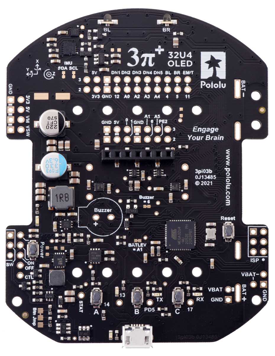
If you want your additional electronics to send or receive information from the AVR, you will need to connect them to one or more of the AVR’s I/O pins. Each I/O pin is already being used for some other purpose, as documented in Section 5.9, so you might need to disable or disconnect one of the other features of the 3pi+ 32U4.
If you do not need some or all of the reflectance sensors or bump sensors, you can free up as many as 8 pins for other purposes: pin 12 (PD6), pin 18 (A0/PF7), pin 20 (A2/PF5), pin 21 (A3/PF4), pin 22 (A4/PF1), pin 4 (PD4), pin 5 (PC6), and pin 11 (PB7). Each pin can be used for digital input and output, while 5 of them (all except pin 5 and pin 11) can be used as analog inputs. Pin 5 can also be used for PWM output. If you want to use these pins as digital or analog inputs, you might need to disconnect them from the sensors by cutting the trace between the appropriate pair of through-holes on the underside of the board (see Section 5.5). If you only want to use one of these pins as an output, you might not need to cut its trace.
If you do not need the AVR to be able to measure the battery voltage, you can use pin 19 (A1, PF6) for other purposes. This pin can be used for digital input and output, as well as analog input. If you want to use this pin as a digital or analog input, you might need to cut the surface-mount jumper labeled “BATLEV = A1” in order to disconnect it from the VBAT voltage divider. If you only want to use A1 as an output, you might not need to cut that jumper.
If you do not need the display, you can remove it. This frees up pin 0 (PD2) and pin 1 (PD3). These pins are the transmit (TX) and receive (RX) pins of the UART, so you can use them to establish serial communication with another microcontroller. These pins are also capable of digital I/O. These pins are the recommended pins for connecting two output channels from an RC receiver, or for controlling two RC servos, because they are arranged in a convenient way with respect to power and ground on the right-side expansion header.
On the original (LCD) version of the 3pi+ 32U4, if you have removed the LCD and do not need to use button A, this frees up pin 14 (PB3). Pin 14 is capable of digital input and output. Removing the LCD also frees up the LCD contrast potentiometer for other purposes. The output of the potentiometer is a 0 V to 5 V signal which is accessible on the LCD connector. It can be connected to any free analog input if you want to read it from the AVR, or it might be useful to connect it to the other electronics that you are adding.
If you do not need to use the buzzer, you can cut the surface-mount jumper labeled “Buzzer = 6”. This disconnects pin 6 (PD7) from the buzzer, so it can be used for other things. Pin 6 (PD7) can be used as a PWM output, digital I/O line, or analog input. Disabling the buzzer also frees up Timer4, which has several PWM output pins. These pins can be used as PWM outputs if they are not needed for their normal tasks.
Be careful about connecting electronics to pin 13 (PC7), pin 17 (PB0), and PD5. These pins are used to control the LEDs on the 3pi+ 32U4. All three of these pins are controlled as outputs by the bootloader. Pin 17 (PB0) and PD5 are used as RX and TX indicators, so if you are sending or receiving data over USB then the Arduino USB code will drive those pins in its interrupt service routines while your sketch is running.
It should be possible to attach additional I²C slave devices to the 3pi+ 32U4’s I²C bus without giving up any features as long as the additional devices’ slave addresses do not conflict with those of the inertial sensors. (The sensors’ addresses are specified in their respective datasheets, which can be found in Section 5.6). The I²C pins (pins 2 and 3) operate at 5 V, so level shifters might be necessary to interface with other devices that use different voltages. (The level-shifted 3.3 V signals used by the inertial sensors are not available to the user.)
If you do not want to use the inertial sensors on the 3pi+ 32U4’s I²C bus, you can cut the surface-mount jumpers labeled “SDA” and “SCL” under “IMU”. This frees up pin 2 (PD1) and pin 3 (PD0). These pins can be used as digital inputs and outputs.
Power
Many of the 3pi+’s power nodes are accessible from the header at the front left of the board. If you power additional devices from VSW, then they will be powered whenever the 3pi+’s power switch is in the ON position, and they will receive whatever voltage the batteries are outputting. If you power them from VM, they will get 8 V power, shared with the motor drivers, whenever the batteries are installed and the power switch circuit is on (but they cannot be powered from USB). If you power them from the 5V pin, then they will receive 5V power whenever the 3pi+ 32U4 logic components are powered. If you power them from 3V3, they will receive 3.3V power whenever the 3pi+ 32U4 logic components are powered. For more information about these power nodes and how much current they can provide, see Section 5.7.
It is also possible to add your own power switch to control power to the 3pi+, as described in Section 5.7.
Ground
You should make sure that all the grounds in your system are connected. The 3pi+ 32U4’s ground node can be accessed from pins labeled “GND”. It should be connected to the ground node of every other circuit board or device you add to the robot.
Related products


Home | Forum | Blog | Support | Ordering Information | Lists | Distributors | BIG Order Form | About | Contact
© 2001–2026 Pololu Corporation
