Support » Pololu 3pi+ 32U4 User’s Guide » 5. The 3pi+ 32U4 in detail »
5.5. Line and bump sensors
The 3pi+ 32U4 features five downward-facing line sensors and two forward-facing bump sensors.
The five line sensors are on the underside of the board along the front edge and can help the 3pi+ distinguish between light and dark surfaces. Each reflectance sensor consists of a down-facing infrared (IR) emitter LED paired with a phototransistor that can detect reflected infrared light from the LED. The reflectance sensors operate on the same principles as our RC-type QTR reflectance sensors: the AVR uses an I/O line to drive the sensor output high, and then measures the time for the output voltage to decay. You can read more about the operating principles of these sensors in our QTR Reflectance Sensor Application Note.
The five line sensors are numbered 1 through 5, with line sensor 1 being the robot’s left-most sensor. In the schematics, they are referred to as DOWN1, DOWN2, DOWN3, DOWN4, and DOWN5. On the control board, their signals are labeled DN1, DN2, DN3, DN4, and DN5.
The two bump sensors are also reflectance sensors, but rather than providing simple reflectance readings, these are designed to measure changes in reflected light as the corresponding bump sensor flaps on the front of the 3pi+’s bumper skirt are pressed (deflected). This allows the 3pi+ to detect when it has contacted another object in front of it and determine which side the contact is on. The left and right bump sensors’ signals are labeled BUMPL and BUMPR in the schematics and BL and BR on the control board.
Each sensor output is protected by a 220 Ohm resistor to help prevent short circuits when the AVR is driving the corresponding I/O line.
The infrared emitters for both the line and bump sensors are controlled by the same pin, labeled EMIT. Driving this pin high illuminates the line sensor emitters, while driving it low illuminates the bump sensor emitters. When EMIT is not driven, as happens if the connected AVR pin is set to be an input, both sets of emitters will effectively be off (a small amount of current will still flow through them, but it is well under 1 mA).
The Pololu3piPlus32U4 library provides functions to help with reading the line sensors and bump sensors, and it handles control of the emitters appropriately (see Section 7).
Ambient light considerations
Since the line sensors and bump sensors rely on measurements of reflected infrared light, they are strongly affected by ambient sources of IR light in the surrounding environment (e.g. sunlight or strong incandescent lighting).
You can help compensate for ambient IR light by incorporating some calibration procedures in your programs. For example, the line sensors can measure the reflectance of light and dark surfaces during calibration and then report subsequent readings relative to this range, while the bump sensors can take baseline readings with the skirt flaps in their unpressed positions and then detect presses based on differences from the baselines. The Pololu3piPlus32U4 library provides support for calibrating both types of sensors in these ways.
However, this calibration is not foolproof; too much ambient infrared light can still prevent the line sensors and bump sensors from working well, and the calibration will not remain effective if the ambient light level changes, such as if the 3pi+ moves from a brightly lit area to a more shaded area. The bump sensors can be especially susceptible to spurious or missed detections since they work by detecting changes in the IR light intensity.
Pin assignments and remapping
By default, the line and bump sensors support these pin assignments:
- Pin 12 is connected to line sensor 1 (DN1).
- Pin A0 (18) is connected to line sensor 2 (DN3).
- Pin A2 (20) is connected to line sensor 3 (DN3).
- Pin A3 (21) is connected to line sensor 4 (DN4).
- Pin A4 (22) is connected to line sensor 5 (DN5).
- Pin 4 is connected to the left bump sensor (BL).
- Pin 5 is connected to the right bump sensor (BR).
- Pin 11 is connected to the shared emitter control pin (EMIT).
These connections are made through traces connecting pairs of through-holes in the front expansion header of the 3pi+ 32U4 control board. A connection can be remapped by cutting the corresponding trace on the underside of the board and making a new connection between the sensor signal and another AVR pin of your choice.
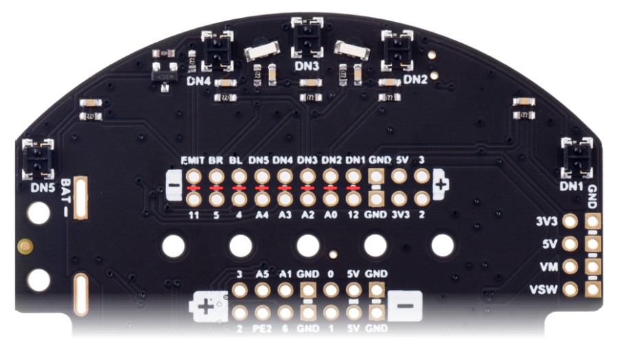 |
Bottom view of the 3pi+ 32U4 Control Board, showing cuttable traces for remapping sensors. |
|---|
Related products


Home | Forum | Blog | Support | Ordering Information | Lists | Distributors | BIG Order Form | About | Contact
© 2001–2026 Pololu Corporation
