Support »
Pololu A-Star 328PB User’s Guide
View document on multiple pages.
You can also view this document as a printable PDF.
- 1. Overview
- 2. Contacting Pololu
- 3. A-Star 328PB Micro pinout and components
- 4. Getting Started
- 5. The A-Star 328PB Serial Bootloader
1. Overview
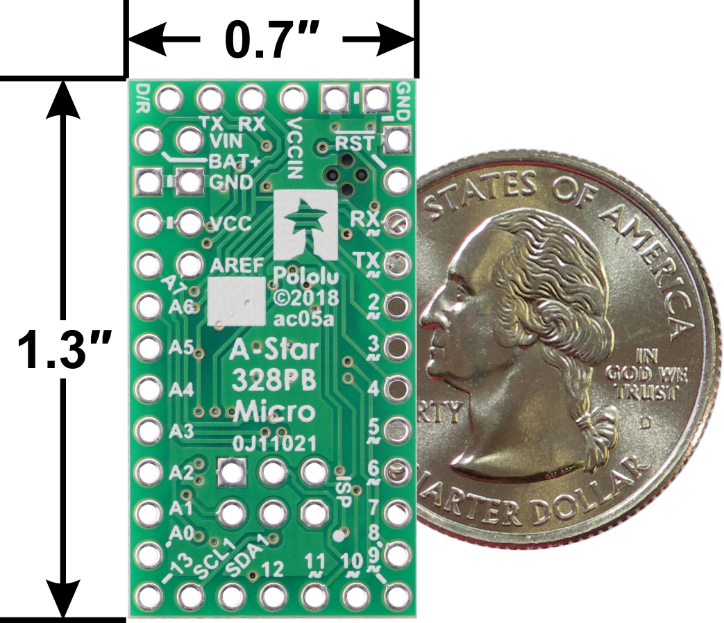 |
A-Star 328PB Micro, bottom view with dimensions. |
|---|
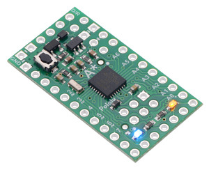
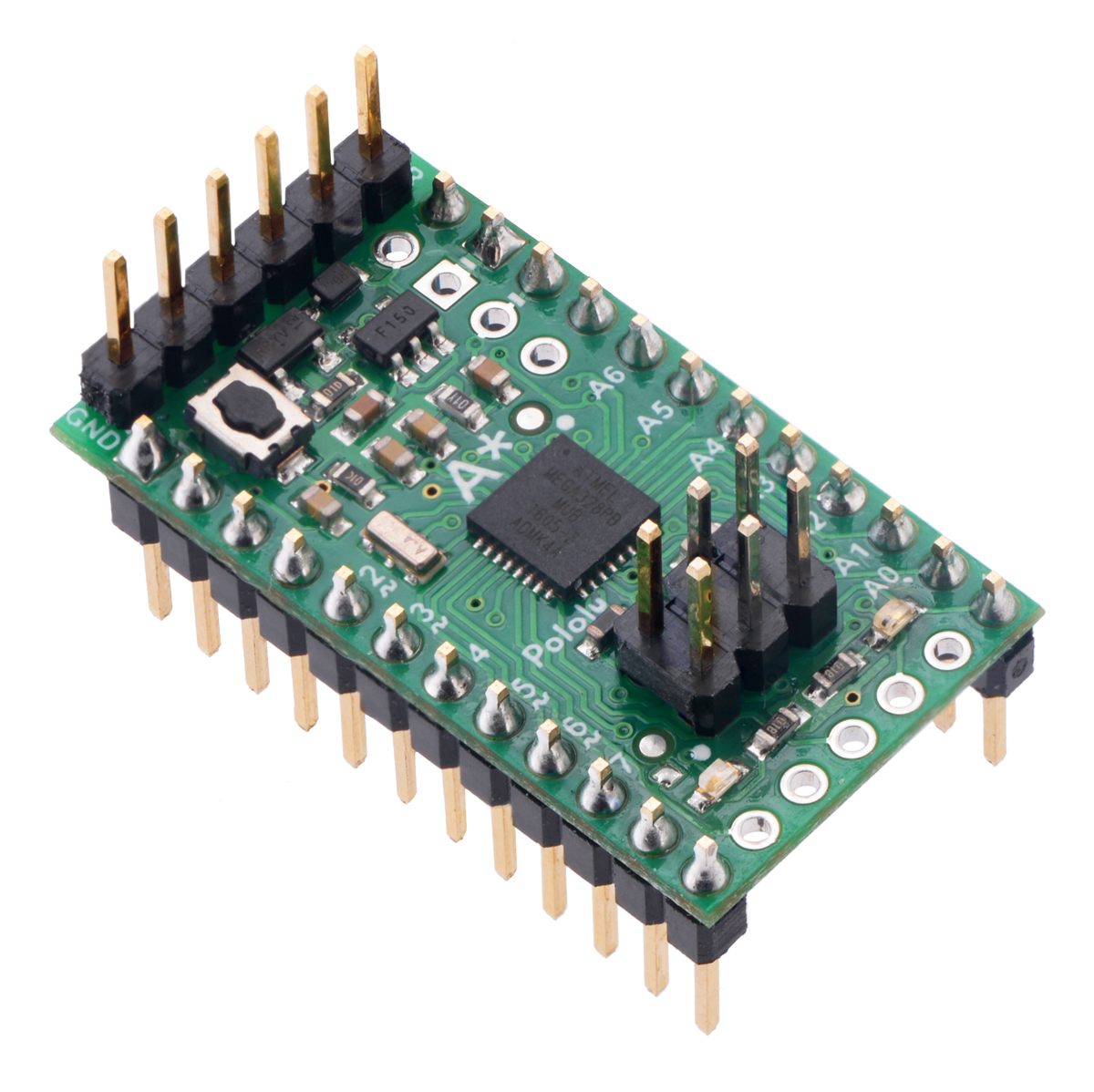
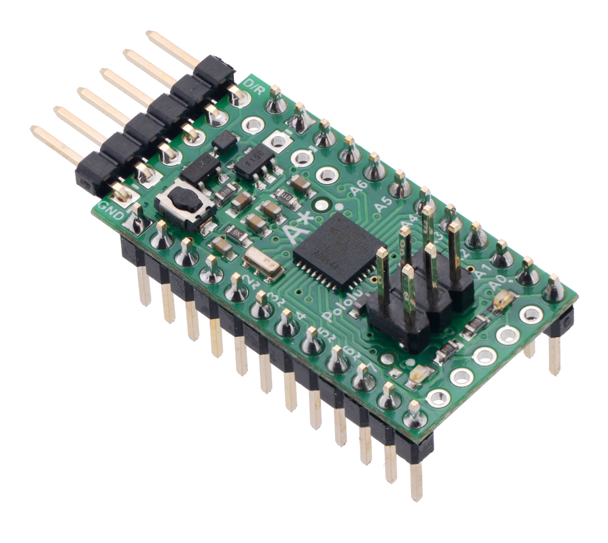
The Pololu A-Star 328PB Micro is a general-purpose programmable module based on the ATmega328PB AVR microcontroller, which has 32 KB of flash program memory and 2 KB of RAM. The ATmega328PB is a backward-compatible, improved replacement for the popular ATmega328P found on other programmable modules like our Baby Orangutan B-328 and the Arduino Uno and Pro Mini, so programs written for those other boards will generally work on the A-Star 328PB Micro with appropriate adjustments for any differences in clock speed. On-board features of the A-Star (abbreviated A*) include a resonator, user and power LEDs, and a reset button. The board includes a low-dropout linear voltage regulator that allows it to be powered from external supplies up to 15 V, and reverse voltage protection on this main power input helps safeguard against accidental damage. The board can also be powered through its TTL serial header by a USB-to-serial adapter, and an integrated power switching circuit makes it safe to have both supplies connected at the same time.
The A-Star 328PB Micro breaks out 19 general-purpose I/O lines along two rows of pins, including seven usable as PWM outputs and eight usable as analog inputs; another five GPIO pins (including two usable as PWM outputs) can be accessed along the bottom edge of the board. It provides both an in-system programming (ISP) header and a connector for TTL serial programming along the top edge. The board fits all this into a 1.3″ × 0.7″ area (the same size as the Arduino Pro Mini), and its 0.1″ pin spacing makes the A* easy to use with solderless breadboards, perfboards, and 0.1″-pitch connectors.
The A-Star 328PB Micro is available in four logic voltage and resonator frequency combinations:
- 5 V, 16 MHz (blue power LED)
- 5 V, 20 MHz (red power LED) Note: See speed warning below.
- 3.3 V, 8 MHz (green power LED)
- 3.3 V, 12 MHz (yellow power LED)
Each of the four versions uses a different power LED color as a way to differentiate them.
Speed warning for 20 MHz version: The 20 MHz resonator frequency exceeds the maximum explicitly allowed in the ATmega328PB datasheet. In our basic testing, the 20 MHz resonator appears to function without problems, but for any critical applications you should confirm for yourself that this product is appropriate.
Either a USB-to-serial adapter or an AVR in-system programmer (ISP) is required to program the A-Star 328PB Micro from a computer. We recommend our USB AVR Programmer v2.1, which can be used as both, and can be configured to run at either 3.3 V or 5 V.
Features
- Dimensions: 1.3″ × 0.7″
- Programmable ATmega328PB AVR microcontroller
- 32 KB flash (0.5 KB used by bootloader, leaving 31.5 KB available for user program by default)
- 2 KB SRAM
- 1 KB EEPROM
- All I/O lines from the ATmega328PB broken out in a compact package
- 19 general-purpose I/O pins available along the sides of the board
- 5 additional I/O pins available on bottom edge
- 9 pins can be configured as hardware PWM outputs (7 along sides of board)
- 8 pins can be configured as analog inputs
- Preloaded with Arduino-compatible TTL serial bootloader
- 6-pin TTL serial programming header for use with a USB-to-serial adapter (we recommend our USB AVR Programmer v2.1, which can act as a USB-to-serial adapter)
- 6-pin ISP header for use with an external AVR programmer (we recommend our USB AVR Programmer v2.1)
- Power LED and user-controllable LED
- Reset button
- Two power options:
- 3.8 V to 15 V (3.3 V versions) or 5.5 V to 15 V (5 V versions) on BAT+
- USB-to-serial adapter can supply power to VCCIN on the serial header
- Reverse-voltage protection on BAT+ supply
Differences between the ATmega328P and ATmega328PB
Compared to the ATmega328P (and ATmega328), the ATmega328PB microcontroller offers a number of improvements, including:
- Two additional GPIO pins: PE0 and PE1
- Two pins that were previously analog inputs only (ADC6 and ADC7) can now also be used as digital inputs and outputs: PE2 and PE3
- Two additional 16-bit Timer/Counters: TC3 and TC4 (for a total of two 8-bit timers and three 16-bit timers)
- Three additional PWM output pins
- A second USART (TTL serial port)
- A second TWI (Two-Wire Serial Interface, I²C-compatible)
- A second SPI (Serial Peripheral Interface)
- A peripheral touch controller (PTC) for adding capacitive touch buttons, sliders, and wheels
The ATmega328PB is code-compatible with the ATmega328P, meaning code compiled for an ATmega328P will run as intended on an ATmega328PB. This application note (283k pdf) by Atmel (now part of Microchip) comprehensively describes the differences between the ATmega328PB and its predecessors.
Our Arduino software add-on makes it easy to use the additional GPIO functionality, PWM outputs, and TTL serial port. The other new features of the ATmega328PB can still be used from the Arduino environment through direct register access or custom libraries.
The A-Star family
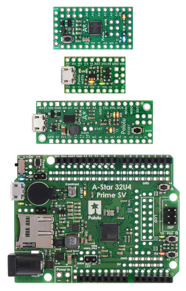 |
From top to bottom: A-Star 328PB Micro, 32U4 Micro, 32U4 Mini SV, and 32U4 Prime SV. |
|---|
The A-Star 328PB Micro is a part of our larger A-Star family, all of whose members are based on AVR microcontrollers and are preloaded with Arduino-compatible bootloaders. The table below shows some key features and specifications of our A-Star microcontroller boards to help you choose the right one for your application.
 |
 |
   |
  |
  | |
|---|---|---|---|---|---|
| A-Star 328PB Micro | A-Star 32U4 Micro | A-Star 32U4 Mini ULV A-Star 32U4 Mini LV A-Star 32U4 Mini SV |
A-Star 32U4 Prime LV A-Star 32U4 Prime SV |
A-Star 32U4 Robot Controller LV A-Star 32U4 Robot Controller SV |
|
| Microcontroller: | ATmega328PB | ATmega32U4 | |||
| User I/O lines: | 24 | 18 | 26 | 26(1) | 26(1) |
| Available PWM outputs: | 9 | 6 | 7 | 7 | 7(1) |
| Analog inputs: | 8 | 8 | 12 | 12 | 12(1) |
| Ground access points: | 6 | 2 | 4 | 43 | 44 |
| User LEDs: | 1 | 2 | 3 | 3 | 3 |
| User pushbuttons: | — | — | — | 3 | 3 |
| USB interface: |  |
|
|
|
|
| Reset button: | |
|
|
|
|
| Power switch: | |
|
|||
| Buzzer option: | |
|
|||
| microSD option: | |
||||
| LCD option: | |
||||
| Motor drivers: | |
||||
| Operating voltage: | 3.3V VCC: 3.8 V to 15 V 5V VCC: 5.5 V to 15 V |
5.5 V to 15 V | ULV: 0.5 V to 5.5 V LV: 2.7 V to 11.8 V SV: 5 V to 40 V |
LV: 2 V to 16 V SV: 5 V to 36 V |
LV: 2.7 V to 11 V SV: 5.5 V to 36 V |
| Regulator type: | 3.3 V or 5 V linear | 5 V linear | 5 V switching ULV: step-up LV: step-up/step-down SV: step-down |
5 V switching LV: step-up/step-down SV: step-down |
5 V switching LV: step-up/step-down SV: step-down |
| Regulated current:(2) | 100 mA | 100 mA | ULV: 500 mA LV: 1 A SV: 800 mA |
LV: 1.8 A SV: 1 A |
LV: 1 A SV: 1.5 A |
| Dimensions: | 1.3″ × 0.7″ | 1″ × 0.6″ | 1.9″ × 0.7″ | 2.8″ × 2.1″ | 2.6″ × 2.2″ |
| Weight: | 1.5 g(3) | 1.3 g(3) | 3.4 g(3) | 13 g to 33 g | 14 g to 23 g |
| Price: | $11.72 | $19.95 | $29.95 to $29.95 | $33.40 to $53.00 | $39.05 to $54.84 |
| 1 Some microcontroller resources are used by on-board hardware. | |||||
| 2 These values are rough approximations for comparison purposes. Available current depends on input voltage, current consumed by the board, ambient conditions, and regulator topology. See product documentation and performance graphs for details. | |||||
| 3 Without included optional headers. | |||||
2. Contacting Pololu
We would be delighted to hear from you about any of your projects and about your experience with the A-Star 328PB. You can contact us directly or post on our forum. Tell us what we did well, what we could improve, what you would like to see in the future, or anything else you would like to say!
3. A-Star 328PB Micro pinout and components
These files document the hardware design of the A-Star 328PB Micro:
- Pinout diagram (579k pdf)
- Schematic diagram (132k pdf)
- Dimension diagram (199k pdf)
- 3D model (5MB step)
- Drill guide (50k dxf)
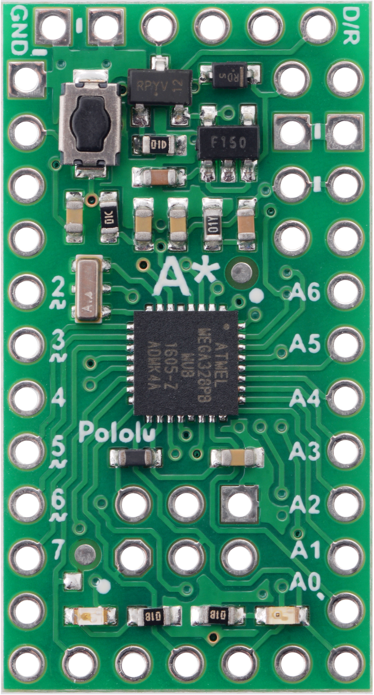
The pinout diagram identifies the I/O and power pins on the A-Star 328PB Micro, and is shown below.
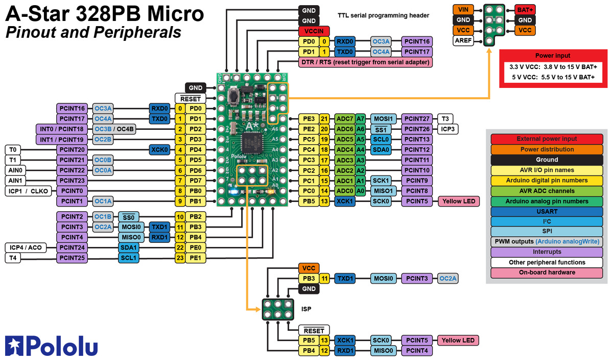 |
The A-Star 328PB is based on the ATmega328PB AVR microcontroller from Atmel (now part of Microchip), and most pins on the board are directly connected to the microcontroller. The A* circuit board has printed indicators that you can use to quickly identify each pin’s capabilities: pins labeled with A0 through A7 can be used as an analog input, and a square wave symbol under the pin number means it can be used as a PWM output. All of the pins are labeled on the bottom silkscreen, and some of the pins are also labeled on the top silkscreen (as space allows). For more information about each pin’s capabilities, see Microchip’s ATmega328PB documentation.
|
|
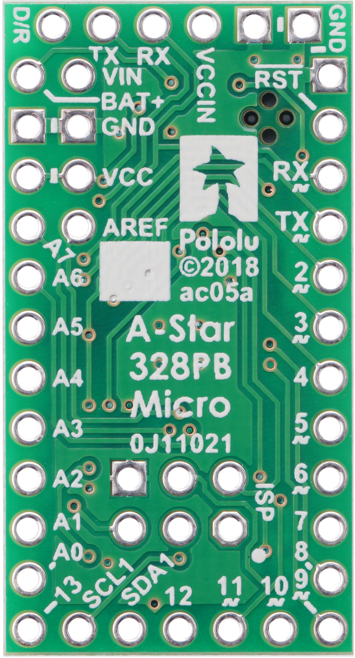
Note that the pins labeled SDA1 (PE0) and SCL1 (PE1) are not limited to being used for TWI/I²C and can be used as general-purpose I/O pins. These pins are new on the ATmega328PB and have no equivalent on the ATmega328P, so they do not yet have official pin numbers in the Arduino environment; therefore, we recommend using the constants SDA1 and SCL1 instead of the pin numbers 22 and 23 in Arduino code. (See Section 4.4 for more information on ATmega328PB support in the Arduino IDE.)
LEDs
The A-Star 328PB has two indicator LEDs:
- A yellow user LED in the lower right is connected to Arduino digital pin 13, or PB5. You can drive this pin high in a user program to turn this LED on.
- A power LED in the lower left indicates when the logic supply voltage, VCC, is present. The color of the power LED depends on the version of the board:
| VCC | Frequency | Power LED color |
|---|---|---|
| 5 V | 16 MHz | Blue |
| 5 V | 20 MHz | Red |
| 3.3 V | 8 MHz | Green |
| 3.3 V | 12 MHz | Yellow |
Connectors
The A-Star 328PB includes a 6-pin header along its top edge that can be used for TTL serial programming with the preloaded Arduino-compatible bootloader. The serial interface is compatible with our USB AVR Programmer v2.1 and commonly available USB-to-serial adapter cables (e.g. FTDI cables). See Section 4.2 for more information about the serial interface. The TTL serial header can also provide power to the A-Star through the VCCIN pin, as detailed below.
The board also has a 6-pin ISP header that allows it to be programmed with an external AVR in-system programmer, such as our USB AVR programmer v2.1. Pin 1 of the header is indicated with a small dot and has an octagonal shape.
|
|
||||
|
|
Power
The main power input for the A-Star 328PB Micro is the BAT+ pin, which is reverse-protected and can accept power sources up to 15 V. Reverse-protected power can be supplied to other devices by using the VIN pin as an output. The VIN voltage feeds into a 100 mA low-dropout (LDO) regulator to provide a regulated 3.3 V or 5 V logic supply called VCC. Alternatively, the external supply can be connected directly between VIN and GND, bypassing the reverse-voltage protection.
The VCCIN pin on the A-Star 328PB Micro serial header functions as a secondary power input for VCC that bypasses the regulator. To avoid unexpected behavior, it is important for the VCCIN voltage to match the regulator voltage on the version you are using. (Supplying a higher voltage to VCCIN raises the logic voltage of your system, and supplying a lower voltage can result in a brownout reset and/or violate the maximum frequency vs. VCC specifications in the ATmega328PB datasheet.)
The A* board includes a switching circuit that makes it safe to have power supplies connected to both VCCIN and BAT+ at the same time, but we do not recommend connecting multiple power sources when the board is powered through VIN instead of BAT+, as the switching circuit does not prevent current from flowing into or out of VCCIN in that situation.
4. Getting Started
4.1. Connecting power
Before you can program the A-Star 328PB, you need to connect power to it.
See Section 3 for information about what kind of power supply you can use and which pins to connect it to.
After you connect power for the first time, you should see the A-Star’s power LED turn on. If you do not see the A-Star 328PB’s power LED turn on when you connect power, double check your connections, make sure your power supply is turned on and working, and make sure any headers pins you are using are soldered.
You should also see the yellow user LED blinking once every two seconds. The default program that we ship on the A-Star 328PB blinks the LED, but this program will be erased when you program the board for the first time, so if your board has been programmed before then you might not see the LED blinking.
After connecting power, it is good to press the board’s reset button to make sure the serial bootloader is working. When you press the reset button, the A-Star 328PB serial bootloader will blink the user LED very quickly three times, wait for one second, and then exit. If you see this triple blink after pressing the reset button, it means the bootloader is present on the device and it can run. If there is no triple blink after you push the reset button, then there might be a problem with your power supply or the bootloader might have been erased.
4.2. Connecting to the serial interface
The A-Star 328PB has a TTL serial interface that allows you to upload programs using the serial bootloader and to send and receive serial data. The serial interface consists of the following six pins:
- GND
- GND, usually connected to CTS on a serial adapter to drive it low
- VCCIN – alternative power input
- TX – TTL serial data output
- RX – TTL serial data input
- D/R – DTR/RTS, used by the serial adapter to trigger a reset
This serial interface is compatible with our USB AVR Programmer v2.1 and commonly available USB-to-serial adapter cables (e.g. FTDI cables). We recommend using the Pololu USB AVR Programmer v2.1 because it can be configured to operate at either 3.3 V or 5 V, and it can program the A* over the ISP interface as well as the serial interface.
The TX and RX lines are directly connected to the ATmega328PB microcontroller, without any level shifting. To avoid issues due to mismatched voltages, it is best to use a USB-to-serial adapter that operates at the same voltage as the A-Star 328PB board you want to program. The Pololu USB AVR Programmer v2.1 can be configured to operate at either 3.3 V or 5 V, so it is suitable for both 3.3 V and 5 V A-Stars.
The VCCIN pin is an alternative power input that you can use to power the A-Star 328PB. Many USB-to-serial adapter cables provide power on this pin, and the Pololu USB AVR Programmer v2.1 can be configured to optionally provide either 3.3 V or 5 V power on this pin. The A* board includes a switching circuit that makes it safe to have both VCCIN and BAT+ power supplies connected at the same time. If power is supplied to VCCIN, It is important for the voltage to match the regulator voltage on your board, as detailed under the “Power” heading in Section 3.
The D/R pin is used to reset the ATmega328PB. It should be connected to the DTR or RTS control signal from the serial adapter, and a falling edge (which occurs when the control signal is asserted) will cause the A-Star’s microcontroller to reset. This feature, called “auto reset”, is often used by Arduino-compatible boards to automatically reset the microcontroller into bootloader mode before a program is serially uploaded to it. If your A-Star is running at 5 V while your serial adapter is running at 3.3 V, the auto reset feature will not work, so we recommend using a serial adapter that operates at the same voltage as the A-Star.
To connect a USB AVR Programmer v2.1 to the A-Star 328PB’s serial interface so that you can upload programs or send and receive serial data, follow these instructions:
- Open the Pololu USB AVR Programmer v2 Configuration Utility software. Set the “Regulator mode” to match the operating voltage of your A-Star. Make sure that the “Line A function” and “Line B functions” settings are set to their default values, which are “(none)” and “DTR” respectively.
- Record the name of the “TTL port” shown in the software. You will need this later when configuring the Arduino IDE or other software to talk to the A-Star.
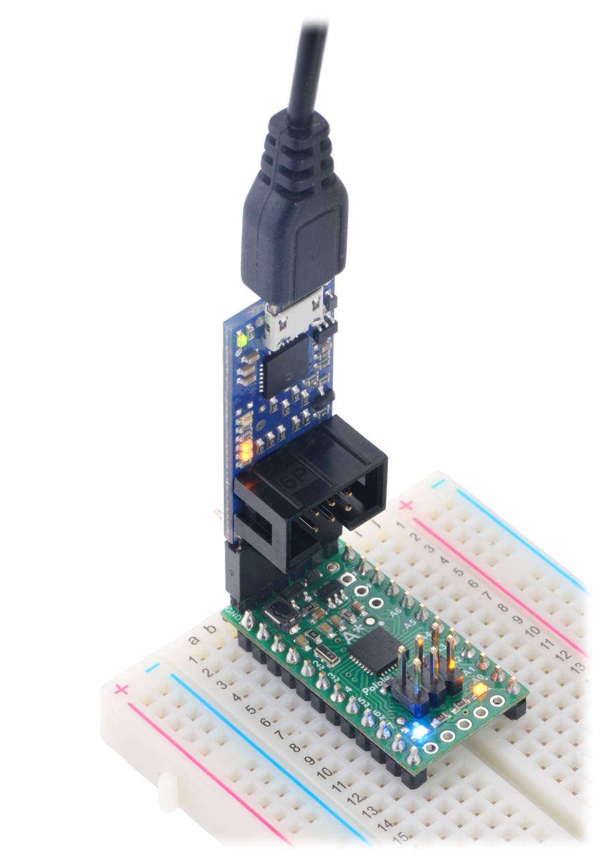
- Connect the programmer’s 6-pin serial interface to the A-Star 328PB’s 6-pin serial interface. If you have soldered male header pins into the A-Star, you can simply plug it into the programmer’s 6-pin female header, with D/R connecting to the programmer’s B pin.
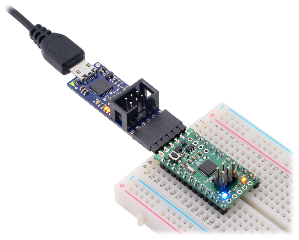 |
A-Star 328PB Micro connected to the serial pins of a Pololu USB AVR Programmer v2.1. |
|---|
4.3. Programming using the Arduino IDE
The A-Star 328PB ships with a preloaded Arduino-compatible TTL serial bootloader (which uses 0.5 KB of flash memory, leaving 31.5 KB available for the user program). We provide a software add-on that enables you to program the board from the Arduino integrated development environment (IDE). The Arduino IDE is a cross-platform, open source application that integrates a C++ code editor, the GNU C++ compiler, and a program upload utility.
These instructions assume that you have already powered your A-Star 328PB (see Section 4.1) and connected its serial interface to your computer using a serial adapter (see Section 4.2).
- Download the Arduino IDE from the Arduino Download page, install it, and start it. These steps were tested with the Arduino IDE 1.8.19, so we recommend using version 1.8.19 or later.
- In the Arduino IDE, open the File menu (Windows/Linux) or the Arduino menu (macOS) and select “Preferences”.
- In the Preferences dialog, find the “Additional Boards Manager URLs” text box (highlighted in the picture below). Copy and paste the following URL into this box:
https://files.pololu.com/arduino/package_pololu_index.json
If there are already other URLs in the box, you can either add this one separated by a comma or click the button next to the box to open an input dialog where you can add the URL on a new line.
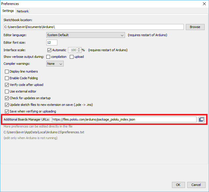 |
Adding a Boards Manager index for Pololu boards in the Arduino IDE’s Preferences dialog. |
|---|
- Click the “OK” button to close the Preferences dialog.
- In the Tools > Board menu, select “Boards Manager…” (at the top of the menu).
- In the Boards Manager dialog, search for “Pololu A-Star Controllers”.
- Select the “Pololu A-Star Controllers” entry in the list, and click the “Install” button.
- After the installation finishes, click the “Close” button to close the Boards Manager dialog.
- In the Tools > Board menu, select “Pololu A-Star 328PB” from the “Pololu A-Star Boards” category. If you do not see the A-Star entries in the Board menu try restarting the Arduino IDE.
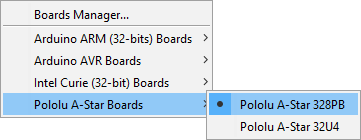 |
Selecting the Pololu A-Star 328PB in the Boards menu. |
|---|
- After you select the A-Star 328PB, the Tools > Version menu should appear. In this menu, select the entry that corresponds to your board.
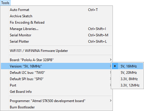 |
Selecting the right version of the A-Star 328PB in the Version menu. |
|---|
- In the Tools > Port menu, select the port for your serial adapter. If you are using the Pololu USB AVR Programmer v2, you should select its TTL port.
- Open up the “Blink” Arduino example, which can be found under File > Examples > 01.Basics > Blink. The code in this example will blink the yellow LED. When you select the Blink example, a new Arduino IDE window will open up. It is OK to close the first window.
 |
Selecting the Blink example in the Arduino IDE. |
|---|
- Press the “Upload” button to compile the sketch and upload it to the device. If everything goes correctly, you will see the message “Done uploading” appear near the bottom of the window. If you see an error message, refer to the “Upload Troubleshooting” section below.
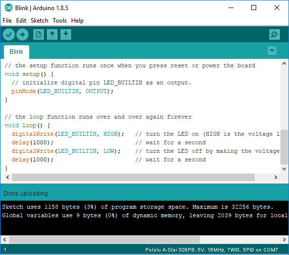
Uploading a sketch to the A-Star 328PB using the Arduino IDE.
- If you uploaded the Blink sketch, then the yellow LED should be blinking once every two seconds. However, we ship the A-Star 328PB with that same example already programmed onto it, so you might not be convinced that anything has changed. Try changing the delay values in the sketch to something else and uploading again to see if you can change the speed of the LED.
After you succeed in programming your device from the Arduino IDE, there are many resources you can use to learn more:
- See Section 4.4 for information about ATmega328PB support in the Arduino IDE.
- The Arduino IDE has many examples that can run on A-Stars.
- The Arduino website has a Language Reference, a wiki called the The Arduino Playground, and other resources.
- The ATmega328PB is very similar to the ATmega328P used on boards like the Arduino Uno, so you can search the Internet for relevant projects that use one of those boards. Almost any code that works on the ATmega328P will work on the ATmega328PB.
Upload troubleshooting
If you get errors when uploading a sketch to the Arduino IDE, here are some things to try:
- Make sure that the A-Star 328PB is powered on (see Section 4.1). The power LED should be on.
- Make sure that the A-Star serial interface is connected to the serial adapter (see Section 4.2) and that the serial adapter is connected to your computer. The A-Star’s GND, RX, TX, and D/R pins must all be connected to the serial adapter.
- Make sure you have selected the right board in the “Board” menu. You can look at the color of power LED to tell what kind of board you have if you are not sure (see Section 3).
- Make sure you have selected the correct port for your serial adapter in the Arduino IDE’s Port menu. If you are using a Pololu USB AVR Programmer v2 as your serial adapter, you can verify that you are connecting to the right port by opening the programmer’s configuration utility and making sure the “TTL port” name shown there matches the selection in the Arduino IDE’s Port menu.
- If the Arduino IDE has trouble connecting to your serial adapter, try unplugging the adapter from your computer, closing any programs that might be using the serial port, restarting the Arduino IDE, and then plugging the adapter back in.
- Try pressing the reset button on the A-Star 328PB to see whether the bootloader is installed and able to run. You should see the yellow user LED blink quickly three times, and then the LED should be off for the next second while the bootloader waits for serial commands. If this test fails, there could be a problem with your power supply or it could be that the bootloader has been erased. If you have previously programmed the A-Star 328PB using the ISP interface, then the bootloader was probably erased and you will need to burn it again as described in Section 5.
- Look at the A-Star 328PB’s user LED after clicking the upload button. If you see it blink quickly three times and then turn off for at least a second, it most likely means that your serial adapter was able to reset the board and start the bootloader.
- Try doing a loopback test to make sure your serial adapter is working: disconnect your serial adapter from the A-Star, then connect its TX line to its RX line. Open the serial monitor in the Arduino IDE, type some letters in the input box at the top, and click send. You should see the letters that you type appear in the output area below, meaning that the serial adapter received those same letters. If the loopback test fails, then you might be connected to the wrong serial port or the serial adapter might be malfunctioning.
- In the Arduino IDE preferences dialog, click the “upload” checkbox next to “Show verbose output during”. The next time you try to upload, the Arduino IDE will show you more details about what is happening.
4.4. ATmega328PB support in the Arduino IDE
Since the A-Star’s ATmega328PB microcontroller is backward-compatible with the ATmega328P commonly used on Arduino boards (like the Arduino Uno and Pro Mini), existing programs and libraries written for a standard Arduino can be used on the A-Star 328PB without any changes (except to account for clock speed differences when necessary). Also, our Arduino IDE add-on includes support for the new features on the ATmega328PB, making them easier to use from the Arduino environment and allowing the A-Star 328PB to be an upgrade from ATmega328P-based boards.
Here are some details about what Arduino features work when programming the A-Star 328PB in the Arduino IDE:
- The
SerialandSerial1objects both work, providing access to USART0 and USART1, respectively. - The “Default I2C bus” sub-menu in the “Tools” menu allows you to choose whether the Wire library and other libraries like it will use TWI0 or TWI1. There is no library support for accessing TWI0 and TWI1 in the same program. However, you can access the registers for both modules and define ISRs for them.
- The “Default SPI bus” sub-menu in the “Tools” menu allows you to choose whether the SPI library and other libraries like it will use SPI0 or SPI1. There is no library support for accessing both SPI0 and SPI1 in the same program. However, you can access the registers for both modules and define ISRs for them.
pinMode,digitalRead, anddigitalWriteshould work on every I/O pin (including A6, A7, SDA1, and SCL1).analogReadshould work on every analog pin (A0 through A7).analogWriteshould work on every pin with PWM (including 0, 1, and 2).
The ATmega328PB has two new pins, PE0 and PE1, that have no equivalent on the ATmega328P. These pins do not yet have official pin numbers in the Arduino environment, so if you need to use their pin numbers in your code, we recommend using the constants SDA1 (for PE0) and SCL1 (for PE1) that are defined in our header files (instead of using the pin numbers 22 and 23 that we have provisionally assigned). For example:
digitalWrite(SDA1, HIGH);
“Upload Using Programmer”
The Arduino IDE provides the ability to upload a sketch to a board using AVR in-system programming (with a programmer connected to the 2×3 ISP header). This is done by running the Upload Using Programmer command in the Sketch menu. Before running that command, you must select the correct Port and Programmer in the Tools menu. If you are using the Pololu USB AVR Programmer v2.1 for in-system programming of the A-Star 328PB, you should select “Atmel STK500 development board” as the programmer.
Note: If you upload using an ISP programmer, you will erase the A-Star’s bootloader. If you want to switch back to programming the board with its serial interface, you will need to burn the bootloader as described in Section 5.
5. The A-Star 328PB Serial Bootloader
The A-Star 328PB comes with a TTL serial bootloader that you can use to upload programs to the board, as described in Section 4.3. This section documents some technical details of the bootloader for advanced users who want to better understand how it works, and it describes how to check if the bootloader is present and how to reload the bootloader if it has been overwritten by ISP programming.
The A-Star 328PB Bootloader is based on the Optiboot bootloader, which is the bootloader used on the Arduino Uno and several other ATmega328 boards. The bootloader is open source and its source code is available on GitHub. The bootloader occupies the upper 512 bytes of the ATmega328PB’s program memory, leaving 31.5 KB for the user program. The bootloader always runs first immediately after the AVR is reset.
The A-Star 328PB Bootloader behaves differently from the Optiboot bootloader on official Arduino boards in a few ways:
- It reports the correct signature (device ID) for the ATmega328PB.
- It enables the internal pull-up resistor on RX (digital pin 0, or PD0) to prevent the pin from floating. (Otherwise, noise on RX could appear to be serial data and keep the microcontroller in bootloader mode.)
- On the 3.3 V, 8 MHz version, the bootloader uses a serial baud rate of 57600 bps, as the ATmega328PB’s USART cannot accurately use a 115200 bps baud rate when running at 8 MHz. (The other versions all use the typical 115200 bps baud rate.)
Brown-out detection
The A-Star 328PB has brown-out detection enabled. The brown-out threshold is 4.3 V on the 5 V versions and 2.7 V on the 3.3 V versions, and if the voltage on VCC goes below this then the AVR will reset.
Checking if the bootloader is present
The bootloader allows programs to be uploaded to the A* through its 6-pin TTL serial programming header. However, when you program the board using the 2×3 ISP header, the bootloader is typically erased.
To verify whether the bootloader is on the microcontroller, reset the A-Star (e.g. by pressing the reset button) and look for three quick flashes of the yellow LED performed by the bootloader, followed by a second of inactivity with the LED off. If you do not see these flashes, the bootloader might have been erased or there might be a problem with your power supply. (Note that if you have a custom program loaded on A-Star that blinks the LED in a similar pattern, it might be hard to tell it apart from the bootloader.)
Burning the bootloader
Follow the instructions below if you want to load the bootloader back onto the board using an ISP programmer such as the Pololu USB AVR Programmer v2.1.
- First, follow the instructions in Section 4.3 up to the point where you would press “Upload” to upload a sketch.
- Open the Tools > Programmer menu in the Arduino IDE and select the appropriate entry for your programmer. If you are using the Pololu USB AVR Programmer v2.1 to burn the bootloader, the correct entry is “Atmel STK500 development board”.
- Open the Tools > Port menu in the Arduino IDE, and change the port to be your programmer’s programming port. This will typically be a different port than the one you would use for uploading sketches via the serial bootloader. If you are using the Pololu USB AVR Programmer v2 to burn the bootloader, the correct port name is the one identified as “Programming port” in the programmer’s configuration software.
- Make sure you have selected the right board in the Tools > Board menu.
- In the Tools menu, select Burn Bootloader. If everything goes correctly, you will see the message “Done burning bootloader.” appear near the bottom of the window.
When you later try to upload programs using the bootloader, don’t forget to select the right port in the Port menu, which will most likely be different than the one you used to burn the bootloader.
If you want to burn the bootloader yourself by directly invoking AVRDUDE, you can get the HEX files for the bootloader in the bootloaders/optiboot folder of the A-Star repository, and you can look in boards.txt in the A-Star repository to find our recommended fuse and lock bit values.


Home | Forum | Blog | Support | Ordering Information | Lists | Distributors | BIG Order Form | About | Contact
© 2001–2026 Pololu Corporation
