Support » Pololu Romi 32U4 Control Board User’s Guide » 3. Romi 32U4 Control Board »
3.7. Raspberry Pi interface and level shifters
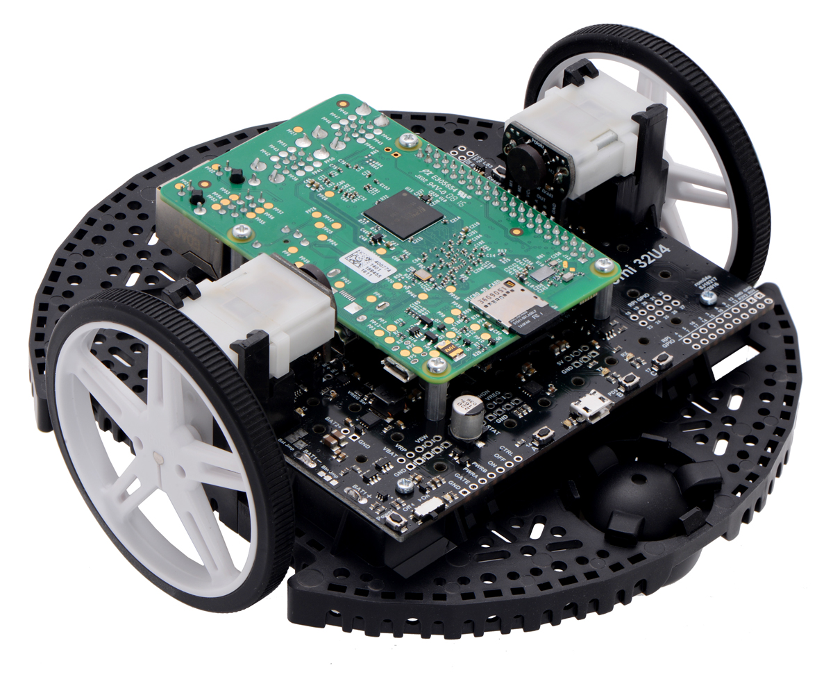
The Romi 32U4 Control Board was designed to be easy to interface with a Raspberry Pi single-board computer to expand the Romi’s processing power. It has a connector and mounting holes matching the Raspberry Pi HAT (Hardware Attached on Top) specification and is designed to connect to the Model B+ and newer versions of the Raspberry Pi with 40-pin GPIO headers (including the Raspberry Pi 3 Model B and Model A+). A 2×20-pin 0.1″ female header is soldered to the control board, and it ships with a set of four standoffs, screws, and nuts.
 |
I²C communication
When used with a Raspberry Pi, the control board is designed to serve as an auxiliary controller, communicating with the Raspberry Pi using an I²C interface (also known as 2-wire Serial Interface, or TWI). As such, the ATmega32U4 microcontroller’s I²C data and clock lines (SDA and SCL) are connected to the corresponding lines on the Raspberry Pi’s I²C bus 1 through on-board level-shifting circuits. These bidirectional level shifters convert between the AVR’s 5 V logic level and the Raspberry Pi’s 3.3 V logic level.
We have written an Arduino library for our our 32U4 family of boards that lets them act as an I²C slave and provides a framework for communication between the ATmega32U4 and a Raspberry Pi master.
A tutorial on the Pololu blog demonstrates this library and its included example code, using them to make a robot that can be remotely controlled and monitored through a web server running on the Raspberry Pi.
General-purpose level shifters
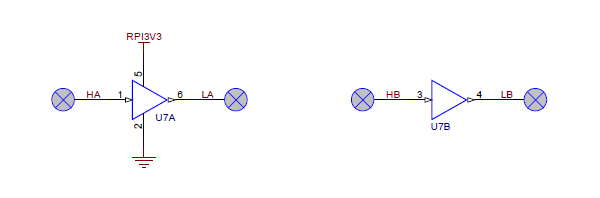
In addition to the dedicated I²C level shifters, the board also makes available a few general-purpose level shifters that are not connected to any signals by default.
LS1 is a dual-channel unidirectional level shifter that converts a pair of 5 V inputs (HA and HB) to a pair of corresponding 3.3 V outputs (LA and LB).
 |
LS2 and LS3 are each single-channel, tristatable, unidirectional level shifters. Each of these exposes four pins: OE (output enable), IN (input), OUT (shifted output), and VCC (logic supply voltage).
- When OE is high, OUT is in a high impedance state.
- When OE is low, OUT matches the state of IN, shifted to the voltage supplied on VCC.
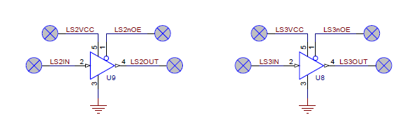 |
For example, if you pull OE low, connect a 3.3 V signal to IN, and connect 5V to VCC, the signal will be shifted to 5 V logic level on OUT.
The input logic level can be 1.8 V to 5.5 V, while VCC (and the output logic level) can be 3 V to 5.5 V. The IN signal can have either a lower or higher logic level than the VCC voltage: you could connect a 5 V signal to IN and a 3.3 V to VCC or a 3.3 V signal to IN and a 5 V to VCC.
Powering the Raspberry Pi from the control board
The control board will provide 5 V power to an attached Raspberry Pi by default. See Section 3.5 for more details about how power is shared and can be controlled between the two boards.
ID EEPROM
The Romi 32U4 Control Board includes a 32-kilobit (4096-byte) EEPROM that connects to the Raspberry Pi’s ID_SD and ID_SC pins. The EEPROM ships with its contents blank, but you can program it as an ID EEPROM in the format specified by the Raspberry Pi HAT specifications, using the utilities provided there. When suitably programmed, the EEPROM can help the Raspberry Pi identify and configure itself to work with the Romi 32U4 Control Board.
Write protection for the EEPROM can be enabled by using solder to bridge the surface-mount jumper labeled “WP” next to the EEPROM chip. (The EEPROM is not write-protected by default.)
Related products


Home | Forum | Blog | Support | Ordering Information | Lists | Distributors | BIG Order Form | About | Contact
© 2001–2026 Pololu Corporation
