Support » Pololu Romi 32U4 Control Board User’s Guide » 3. Romi 32U4 Control Board »
3.6. Expansion areas
The Romi 32U4 Control Board has several expansion areas (primarily in three groups near the front left and middle and back right edges) that break out all of the general-purpose I/O lines from the ATmega32U4 microcontroller and the Raspberry Pi. The board also provides access to various power inputs, outputs, and control pins, and it makes a few stand-alone buses available to help you make connections. The following diagrams identify the locations of these pins and the hardware associated with them; they are also available as a printable PDF (1MB pdf). For more information about the ATmega32U4 microcontroller and its peripherals, see Atmel’s ATmega32U4 documentation.
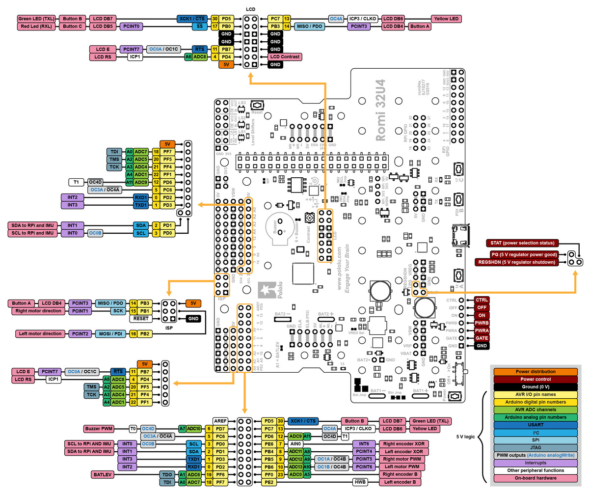 |
Pinout diagram of the Romi 32U4 Control Board (ATmega32U4 pinout, peripherals, and board power control). |
|---|
 |
Pinout diagram of the Romi 32U4 Control Board (Raspberry Pi pinout, peripherals, and level shifters). |
|---|
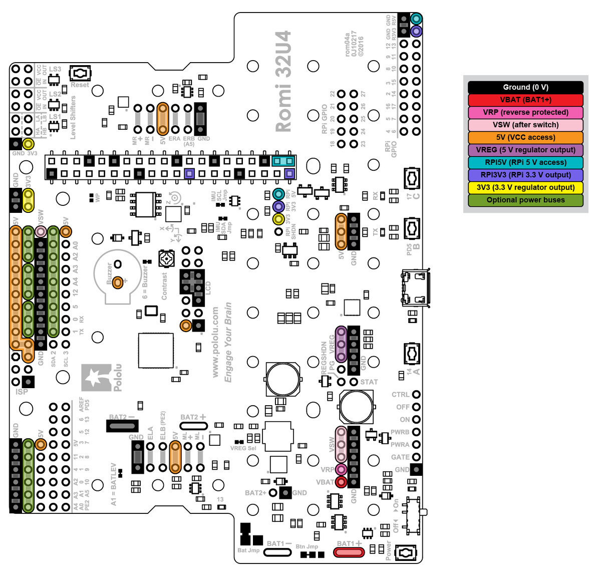 |
Power distribution diagram of the Romi 32U4 Control Board. |
|---|
Related products


Home | Forum | Blog | Support | Ordering Information | Lists | Distributors | BIG Order Form | About | Contact
© 2001–2026 Pololu Corporation
