Support »
Pololu Wixel Shield for Arduino User’s Guide

View document on multiple pages.
You can also view this document as a printable PDF.
1. Overview
The Wixel shield seamlessly enables a wireless link (with a typical range of ~50 feet) to replace your Arduino’s USB interface, which means you can use the standard Arduino computer software to:
- wirelessly program the Arduino (this feature is not available with the Arduino Leonardo or the A-Star 32U4 Prime).
- wirelessly debug sketches with the Arduino serial monitor.
- wirelessly communicate with the Arduino from your computer’s virtual COM port.
More generally, the shield can also be used for wireless communication between an Arduino or Arduino clone and other embedded systems (including additional Arduinos). Alternatively, this board can also be used without an Arduino as a general-purpose Wixel prototyping board.
The Wixel shield does not interfere with the Arduino’s existing USB circuitry, so the Arduino’s traditional wired USB connection can still be used while the shield is connected.
Wireless communication requires a pair of Wixels, which are sold separately or as part of a Wixel shield combination deal. Neither the Wixel shield nor the shield combination deal include an Arduino.
Example Applications
The Wixel shield for Arduino opens the door for many new Arduino projects. Here are just a few project ideas:
- Program, debug/fine-tune, and control your Arduino-based robot without having to touch it.
- Stream data from a remote sensor (e.g. your outdoor weather station) to your computer or Arduino.
- Build a wireless remote control for your Arduino project.
- Maintain projects installed in hard-to-reach places or places where wires and cables would be impractical.
- Enable communication among a swarm of Arduino-based robots or a field of interactive elements (requires additional Wixel development).
- Use the Wixel as a secondary, parallel processor to add more computing power, I/O lines, and hardware peripherals to your Arduino (requires additional Wixel development).
Advanced users can write programs for their Wixels to make use of its 12 free general-purpose I/O lines, including 5 analog inputs, or to develop more complex wireless communication networks.
1.a. Contacting Pololu
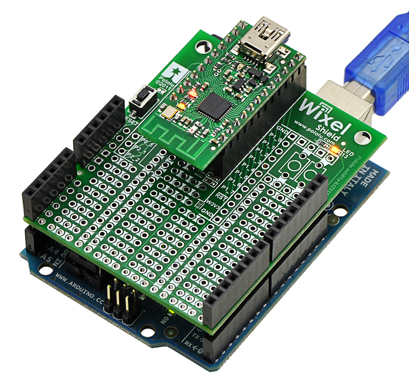
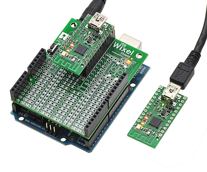 |
Wixel shield for Arduino powered through its power jack, communicating wirelessly with another Wixel. |
|---|
Thank you for your interest in the Wixel Shield for Arduino. If you need technical support for this product or have any feedback you would like to share, you can contact us directly or post on our forum. We would also be delighted to hear from you about any of your projects and about your experience with the Wixel shield. Tell us what we did well, what we could improve, what you would like to see in the future, or anything else you would like to say!
1.b. Shield Features
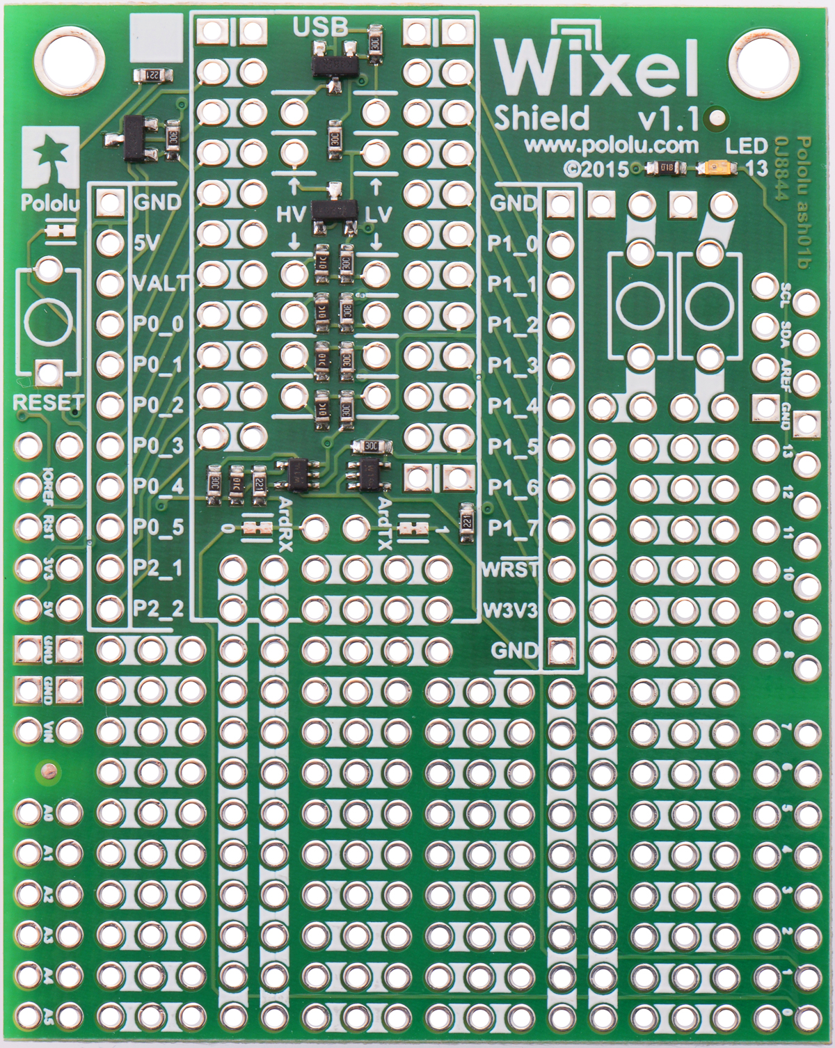 |
Wixel Shield for Arduino, v1.1. |
|---|
Wireless Sketch Uploading
The Wixel shield connections allow it to duplicate the functionality of the USB circuitry on ATmega328-based and ATmega168-based Arduino boards, including the Arduino Uno. This means the shield can wirelessly program the Arduino using the standard Arduino software. These connections do not interfere with the Arduino’s USB interface, so the Arduino’s traditional wired USB connection can still be used while the shield is connected. A schematic of the connections between the Arduino and the Wixel shield is available in Section 1.e. More information on wireless sketch uploading is available in Section 2.c.
General-Purpose Wireless Serial
The Wixel shield makes general-purpose wireless serial communication easy. Arduino serial functions, such as Serial.print(), will transmit data wirelessly from the shield’s Wixel to a remote Wixel that then relays the information to the computer or embedded electronics to which it is connected. Similarly, data from the remote Wixel will be transmitted to the Wixel shield and can be read by Arduino functions like Serial.read(). This enables wireless sketch debugging using the Arduino serial monitor, wireless communication between custom PC software and your Arduino, wireless communication between multiple Arduinos, and more.
Prototyping Space
The unused portions of the Wixel shield are configured as general-purpose prototyping space in which you can construct your own circuits. The holes in this prototyping area are connected in a breadboard-like configuration, as indicated by the top silkscreen. The traces connecting the prototyping holes are located on the bottom side of the shield and can be cut if a particular connection is not desired.
Arduino Reset Button, User LED, and Pins
Since the shield covers the Arduino’s reset button and user LED, the shield makes parallel versions of these components accessible on the shield itself. The shield features an Arduino reset button and a yellow LED (connected to Arduino pin 13). The shield pin spacing along the sides matches the standard (irregular) Arduino pin spacing, but these pins are additionally broken out to neighboring columns that are on a 0.1″ grid. All square pads on the shield are ground.
Voltage Dividers
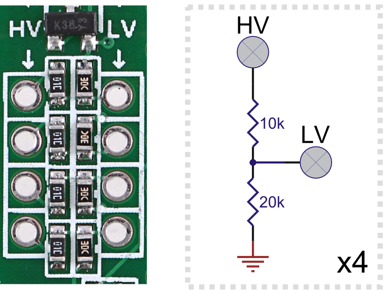 |
The shield has four general-purpose 2/3 voltage dividers that can be accessed by the lower “HV” and “LV” pins (pictured above) located between the Wixel socket pins. These voltage dividers can be used to safely connect 5 V outputs to the Wixel’s 3.3 V inputs: connect the 5 V signal to one of the four HV pins and then connect the corresponding LV pin to the Wixel pin of your choosing. The voltage dividers are not connected to anything by default.
MOSFET Circuits
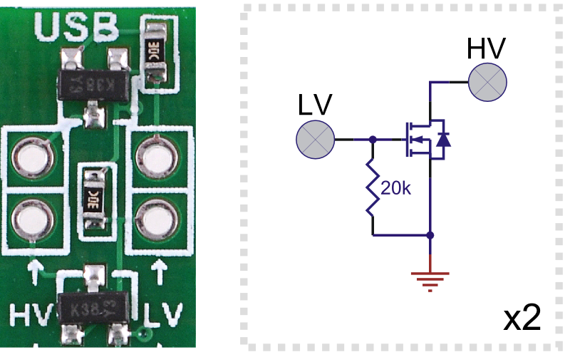 |
The shield has two general-purpose MOSFET circuits that can be accessed by the upper “HV” and “LV” pins (pictured above) located between the Wixel socket pins. These circuits can be used as inverters, level-shifters (e.g. to convert a 3.3 V Wixel output to a 5 V signal), or for driving larger loads (up to 200 mA) than you can with a Wixel or Arduino I/O pin alone (e.g. high-current LEDs or relays). The MOSFET circuits are not connected to anything by default. The circuit incorporates a BSS138 MOSFET (N-channel, 50 V, 200 mA, 1.5 V maximum gate threshold voltage).
Pushbuttons
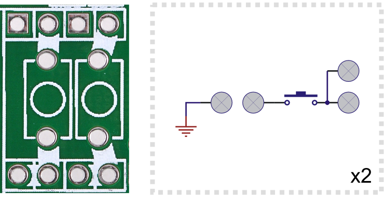 |
The shield has space near the pin 13 LED that can be used for two general-purpose pushbuttons. The pushbutton pins are brought out to a series of through-hole pads that you can connect to other parts of your circuit. One easy way to add user-input pushbuttons to your Arduino is to jumper the upper pushbutton pin to the neighboring ground pad and connect the lower pushbutton pin to the Arduino or Wixel I/O line of your choosing (with that line’s internal pull-up enabled). In this configuration, the line is high by default, and it is driven low when the button is pressed.
Wixel Socket
The shield relies upon a pair of Wixels for its wireless connection. The shield’s Wixel socket allows the Wixel to be removed and used for other applications.
Note: The above features make the Wixel shield a good general-purpose prototyping board for Wixel projects. An Arduino is not required to use this board as a Wixel development platform.
1.c. Arduino Pin Usage
The Wixel shield connects to these pins on the Arduino:
- Pin 0 (RX)
- Pin 1 (TX)
- Pin 13 (user LED)
- RESET
- 5V
- GND
The shield uses the Arduino’s 5 V regulator to power the socketed Wixel. It is safe to use this shield in conjunction with other Arduino shields or electronics that also use these pins, though such electronics could potentially interfere with the operation of the Wixel shield (and vice versa). For details about the connections, see the Wixel shield for Arduino schematic in Section 1.e.
1.d. Jumper settings
As shown in the picture below, the Wixel Shield has a number of surface-mount jumpers that can be used to customize some of the on-board connections.
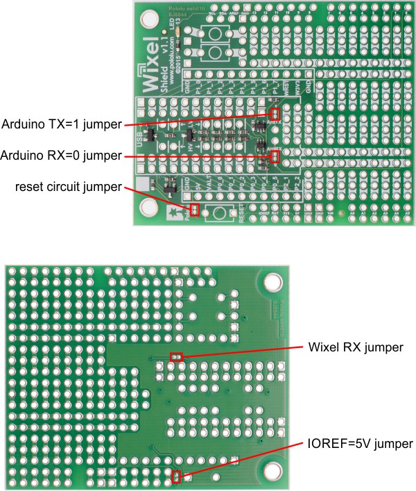 |
Configuration jumpers on the Wixel Shield for Arduino, v1.1. |
|---|
- Reset circuit jumper: This jumper allows a logic high on the Wixel’s P0_0 pin to reset the Arduino by driving its RESET pin low. It is connected by default.
- Arduino RX=0 jumper: The Wixel’s TX output (P1_6) goes to a level shifter that converts it to the Arduino’s IOREF voltage. The output of this level shifter is connected to the Arduino’s pin 0 (RX) by this jumper. It is connected by default, but if you want to use a different pin as RX on your Arduino (e.g. if you are using software serial), you can cut this jumper and make your own connection from the through-hole labeled “ArdRX” to the desired pin.
- Arduino TX=1 jumper: This jumper connects the Arduino’s pin 1 (TX) to the input of a level shifter that converts it to 3.3 V for the Wixel’s RX input (P1_7). It is connected by default, but if you want to use a different pin as TX on your Arduino, you can cut this jumper and remap the connection with the through-hole labeled “ArdTX”.
- Wixel RX jumper: If you are not using serial communication and the output of the level shifter interferes with the Wixel’s P1_7 pin in your application, you can cut this jumper (connected by default) to disconnect the level shifter from P1_7. This jumper is only available on the Wixel Shield v1.1, not the original (v1.0).
- IOREF=5V jumper: By default, the level shifters on the Wixel Shield v1.1 convert between the Arduino’s IOREF voltage and the Wixel’s 3.3 V, allowing the shield to work automatically with both 5 V and 3.3 V Arduino boards. The IOREF pin was introduced by the Arduino Uno R3 and is present on all newer Arduinos, but older boards like the Duemilanove do not have this pin. The shield can still be used with such an Arduino board by bridging this jumper (which is disconnected by default) to connect 5V to IOREF. This jumper is only available on the Wixel Shield v1.1, not the original (v1.0), which always shifts between 5 V for the Arduino and 3.3 V for the Wixel.
1.e. Schematic Diagram
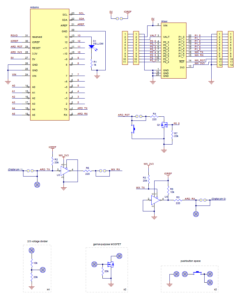 |
This schematic is also available as a downloadable pdf: Wixel Shield for Arduino, v1.1 schematic (153k pdf)
For schematics of older versions, see Section 3.
1.f. Dimensions
The shield board dimensions are 2.02″ × 2.56″ (within the profile of the standard Arduinos). When the shield—with a socketed Wixel—is plugged into an Arduino Uno, the entire assembly is 1.3″ tall.
With the socketed Wixel but without the extended shield headers, the shield itself is 0.8″ tall. Since the height of the Wixel and its socket is taller than the typical available clearance between shields, we recommend using the Wixel shield as your Arduino’s top shield.
The mounting holes are 1.7″ apart and 0.125″ in diameter, suitable for #4 screws.
2. Getting Started
2.a. What You Will Need
The following materials are necessary for getting started with your Wixel shield for Arduino:
- An Arduino or compatible control board. Using this product as an Arduino shield (rather than a general-purpose Wixel prototyping board) requires an Arduino. Wixel shield should work with all Arduino and Arduino clones that have the standard Arduino pinout and use a serial bootloader. We have specifically tested it with:
- Arduino Uno (both original and R3)
- Arduino Duemilanove (with ATmega168)
- Arduino Mega 2560
- Arduino Leonardo — wireless communication is possible, but the Leonardo is not compatible with wireless programming because it uses a USB bootloader.
- A-Star 32U4 Prime — just as with the Leonardo, wireless communication is possible, but the A-Star 32U4 Prime is not compatible with wireless programming because it uses a USB bootloader.
- chipKIT Max32 Arduino-Compatible Prototyping Platform (PIC32-based Arduino clone)
- Two Wixels. A pair of Wixels make the wireless link that the shield relies on.
- A USB A to mini-B cable. You will need a USB A to mini-B cable to connect your Wixels to your computer.
- A soldering iron and solder. The through-hole parts included with the Wixel shield must be soldered in before you can plug the shield into an Arduino or plug a Wixel into the shield. An inexpensive soldering iron will work, but you might consider investing in a higher-performance soldering iron if you will be doing a lot of work with electronics. See Section 2.b for more information on assembling the Wixel shield.
- A desktop or laptop computer. You will need a personal computer for configuring the Wixels and using the Arduino Software. Currently, the Wixel Configuration Utility, the software used to configure the Wixels, only works under Windows, but once configured, the Wixels should work with Windows, Linux, or Mac. See Section 2.c for more information on configuring the Wixels for use with the Wixel shield.
We offer a combination deal that consists of a Wixel shield, two Wixels, and a USB A to mini-B cable.
2.b. Assembly
The Wixel shield ships with all of the surface-mount parts populated. However, soldering is required for assembly of the included through-hole parts. The following through-hole parts are included with the Wixel shield:
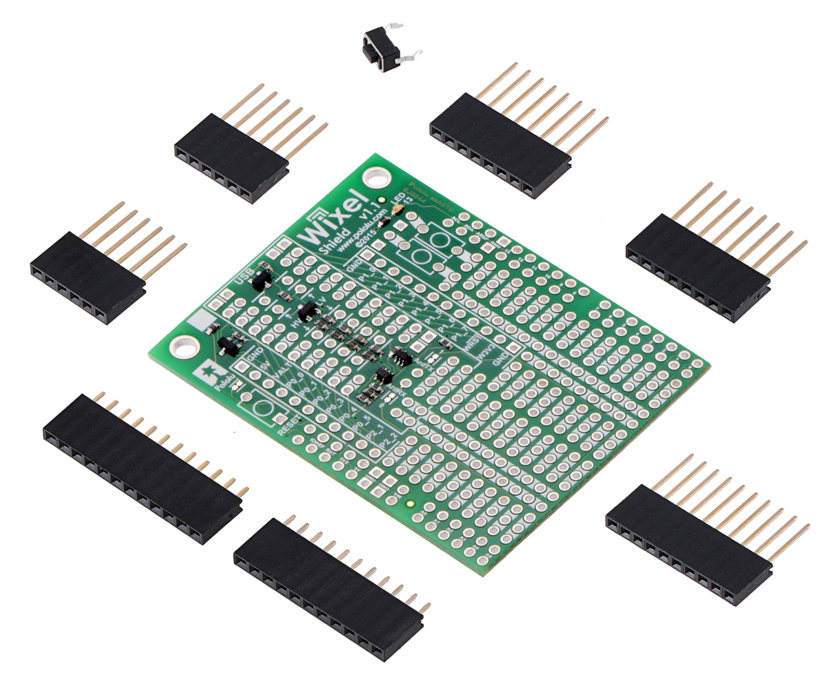 |
Wixel shield for Arduino, v1.1 with included hardware. |
|---|
- one extended/stackable 1×10 female header (for Arduino shields)
- two extended/stackable 1×8 female headers (for Arduino shields)
- two extended 1×6 female headers (for Arduino shields)
- one 1×12 female header (Wixel socket header)
- one 1×11 female header (Wixel socket header)
- one pushbutton (Arduino reset button)
This provides everything you need to plug an assembled Wixel into the shield and the shield into an Arduino.
The left picture below shows a fully-assembled Wixel shield, and the right picture below shows that assembled shield being used with a Wixel and an Arduino Uno. Note that the header pins should be soldered into the outer rows of through-holes as shown in the pictures below; the inner rows provide additional access to the Arduino and Wixel pins.
The newest Arduino boards, including the Uno R3, the Leonardo, and our A-Star 32U4 Prime boards, use one 10×1 header, two 8×1 headers, and one 6×1 header; older Arduino boards use two 8×1 headers and two 6×1 headers. Please make sure you solder the appropriate headers for your particular Arduino!
|
|

Note: If the headers are not soldered in straight, it might be difficult to plug the shield into the Arduino or the Wixel into the shield. One technique for soldering headers on straight is to solder only a single header pin to the shield. If the header is not straight, you can melt the solder on this pin with your soldering iron and adjust the header with your free hand until it is. You should only solder the rest of the header pins when you are sure the header is straight.
If none of your Wixels has header pins soldered in, you will need to assemble at least one Wixel with the included male headers as shown in the picture below:
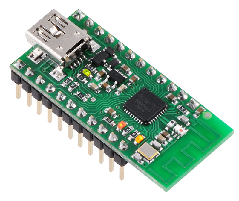 |
Once the male header pins are installed, the Wixel can be plugged into the female socket on the Wixel shield. You can skip this step if you purchased a fully-assembled version of the Wixel.
2.c. Configuring the Wixels
Before your Wixels will work with the Wixel Shield for Arduino, they need to be programmed with a compatible app. The Wixels do not ship with an app on them, so you will need to configure them using the Wixel Configuration Utility on a Windows computer. The Wixel User’s Guide contains instructions for downloading, installing, and using the Wixel Configuraiton Utility.
Wixel Shield App
The quickest way to get started with your Wixel shield is to load both Wixels with our open-source Wixel Shield app (25k wxl). This special version of the Wireless Serial app, which is documented in the Wixel User’s Guide, creates a wireless serial link between two Wixels and enables wireless Arduino sketch uploading (using the standard Arduino computer software) in addition to general-purpose wireless communication.
The app has two configuration parameters: radio_channel and baud_rate. Both Wixels need to use the same radio_channel, and the baud_rate needs to be set to the specific upload speed/bootloader baud rate for your Arduino, as shown in the table below. (Other baud rates will work for serial communication, but they will not work for wireless Arduino programming.)
| Arduino board name | Upload speed/baud_rate |
|---|---|
| Arduino Uno | 115200 |
| Arduino Duemilanove w/ ATmega328 | 57600 |
| Arduino Diecimila or Duemilanove w/ ATmega168 | 19200 |
| Other | Use upload.speed parameter in Arduino boards.txt file |
Making Your Own Compatible Apps
Compatible apps, at a minimum, must do two things: relay serial communication and reset the Arduino when the Arduino software signals a reset. To accomplish this, they should use the following three Wixel pins:
- P0_0 – the Arduino is held in reset while this pin is high
- P1_6 – Wixel TX/Arduino RX
- P1_7 – Wixel RX/Arduino TX
The other 12 general-purpose I/O pins including 5 analog inputs are free to be used by your app to interface with the Arduino or other electronics.
A good starting point for making your own compatible app is to modify the source code for the Wireless Serial App, which is available in the Wixel SDK and included as part of the Wixel Development Bundle. The Wixel User’s Guide has more information on making your own Wixel apps in Section 10.
2.d. Connecting the Shield
As with most electronics, it is good to avoid making connections while circuits are energized. Therefore, we recommend that your Arduino be unpowered and disconnected from USB when plugging or unplugging the shield from it. The same goes for the socketed Wixel. After all of the connections between the Wixel, shield, and Arduino are secure, the Arduino can safely be powered through the power jack or USB. It is safe to connect the socketed Wixel to your computer through USB, but the Arduino will not receive power through that connection.
|
2.e. Using the Arduino Software
Using the Arduino software with the Wixel shield for Arduino is not any different than using it normally, except that you will be programming on the COM port associated with a Wixel rather than one associated with your Arduino. In the Arduino IDE, select your Arduino board using Tools->Board and select the the COM port that corresponds to the Wixel connected to your computer using Tools->Serial Port. The upload button and the serial monitor will now work exactly like they do when your Arduino is directly connected to your computer via USB.
2.f. Writing Sketches for the Wixel Shield
Writing sketches for the Wixel shield is as easy as using the standard serial library to transmit and receive serial data. Note that when first enabling the serial port, you might receive an invalid serial byte as a result of noise on the serial lines. You can keep the Wixel from receiving this noise byte by delaying for ten milliseconds before and after calling Serial.begin(), like this:
delay(10);
Serial.begin(115200); // change this baud rate to the baud rate you set on your Wixel
delay(10);
Example Serial Communication Sketch
Here is a sketch (based off of the example physical pixel sketch) that demonstrates wireless serial communication between an Arduino and a computer:
const int ledPin = 13; // the pin that the LED is attached to
int incomingByte;      // a variable to read incoming serial data into

void setup() {
  // initialize serial communication:
  delay(10);
  Serial.begin(115200); // *** NOTE: change this to the baud rate you set on your Wixel
  delay(10);
  Serial.println("Wireless Physical Pixel");
  Serial.println("Send 'H' to turn on the LED and 'L' to turn off the LED.");
  // initialize the LED pin as an output:
  pinMode(ledPin, OUTPUT);
}

void loop() {
  // see if there's incoming serial data:
  if (Serial.available() > 0) {
    // read the oldest byte in the serial buffer:
    incomingByte = Serial.read();
    // if it's a capital H (ASCII 72), turn on the LED:
    if (incomingByte == 'H') {
      digitalWrite(ledPin, HIGH);
      Serial.println("LED is on");
    }
    // if it's an L (ASCII 76) turn off the LED:
    if (incomingByte == 'L') {
      digitalWrite(ledPin, LOW);
      Serial.println("LED is off");
    }
  }
}
If you paste this code into an empty sketch, you should be able to wirelessly upload it to your Arduino and use the serial monitor to communicate with your Arduino. In the serial monitor, you should see instructions for how to use the sketch.
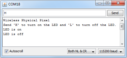 |
Serial monitor connected to an Arduino running the Wireless Physical Pixel sketch. |
|---|
3. Differences between board revisions
There have been two versions of the Wixel Shield for Arduino, the original (v1.0) and the current v1.1. While either version should generally be a drop-in replacement for the other, there are some minor differences between the two versions.
 |
The first revision, released in June 2011, was version 1.0 (ash01a).
This version predated the Arduino Uno R3, so it lacked pass-throughs for the four new pins present on the R3 and all newer Arduinos.
Schematic diagram for v1.0 (39k pdf)
|
The second and latest revision, released in April 2016, is version 1.1 (ash01b).
Compared to v1.0, the following changes were made:
- Pass-throughs were added for the four additional pins (SCL, SDA, IOREF, and an unused pin) on the Arduino Uno R3 and all newer Arduinos.
- The reset button was moved slightly to make room for the new pass-throughs.
- The UART (serial) level shifter circuits were changed to convert between the Arduino’s IOREF voltage and the Wixel’s 3.3 V instead of always using 5 V on the Arduino side.
- Through-hole access points (ArdTX and ArdRX) were added to make it easier to remap the Arduino’s serial pins, which reduces the size of prototyping area very slightly.
Schematic diagram for v1.1 (153k pdf)
Related products


Home | Forum | Blog | Support | Ordering Information | Lists | Distributors | BIG Order Form | About | Contact
© 2001–2026 Pololu Corporation
