Pololu Blog »
David's line following robot that learns the course
 |
Several people here made robots to compete in the recent LVBots line following competition. The goal of the competition is to make an autonomous robot that follows a line on the ground as fast as possible. I made a robot called LearnBot for the competition. LearnBot is able to learn the line course on the first lap and then use that information to its advantage on the second and third laps.
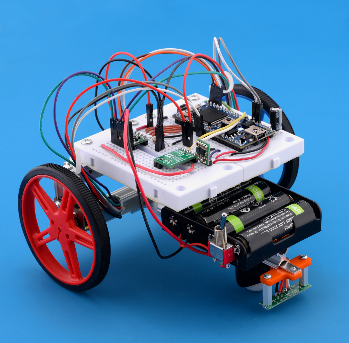
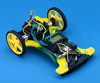
This is actually the same robot that I used in the dead reckoning contest last year. See my previous post about the robot if you want to know about its hardware.
Most of the line following robots that I have seen at LVBots and on our forum run simple software: they read their line sensors to get an idea of how well they are aligned, and then they adjust their motors based on that using a PID algorithm. If you are not familiar with how a simple line follower works, I recommend reading the “Line Following” example project in the Pololu 3pi Robot User’s Guide. This robot does all the same things as a simple line follower, but it also learns the course at the same time.
This robot uses optical quadrature encoders to measure how far it has traveled. The optical encoders were the best option available in 2014 when the robot was originally built, but if I were building it again today, I would use the newer magnetic encoders, since they output cleaner signals and are not affected by light from the environment.
The robot also has a MinIMU-9 v3, which I added for this contest. The MinIMU-9 v3 has a 3-axis gyroscope, 3-axis accelerometer, and 3-axis magnetometer, but I only used the gyroscope. By adding up the readings from the Z axis of the gyroscope on the MinIMU-9 v3 over time, the robot gets a pretty good measurement of its current heading (the direction it is facing). Absolute heading does not matter; the robot just needs to know how far it has turned since starting the course.
By combining the information from the encoders and gyro, the robot can calculate its position relative to the point where it started as a pair of coordinates. In general, it is also possible to use encoders alone to calculate the heading and coordinates, but for this robot I think using the gyro improved the accuracy of the measurements.
With the position measurements, the robot is able to know approximately when it reaches the starting point of the line course. The X and Y axes of my measurements are defined so that the robot initially starts at the origin (0, 0) and is facing in the positive X direction when it starts. To detect its return to the starting point, the robot waits for the X coordinate to change from negative to non-negative at a time when the Y coordinate is close to 0. To avoid false positives, it also checks that the total number of encoder counts detected during this lap is not too small, and it checks that the heading points roughly in the positive X direction.
Every 100 encoder ticks, the robot saves its X and Y coordinates into its log, along with the current heading. The log was very useful for debugging and I also used it to detect straightaways. Here is a visualization of the robot’s log from one of the last test runs I did before the competition:
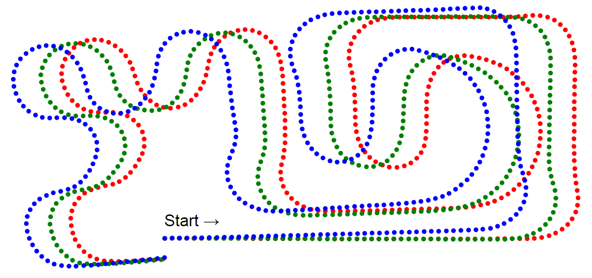 |
Example log data from David’s line follower in 2015, raw. |
|---|
Each dot represents the coordinates from a reading in the robot’s log. The blue dots represent the first lap, while the green dots represent the second lap, and the red dots represent the third lap. When the robot starts the race or detects the start of a new lap, it resets its coordinates to (0, 0) and resets its heading to point in the positive X direction. That is why there is a big gap between the ending dot of one lap and the starting dot of the next lap. The position of the robot at the start of the lap defines the X and Y coordinate axes for that lap, so a little bit of error in the robot’s position at that time can make the whole lap appears shifted or rotated relative to the other laps. If I simply rotate the log data for the first lap by 1.7 degrees and translate the other laps horizontally, I can get the data to match up very nicely, as shown below:
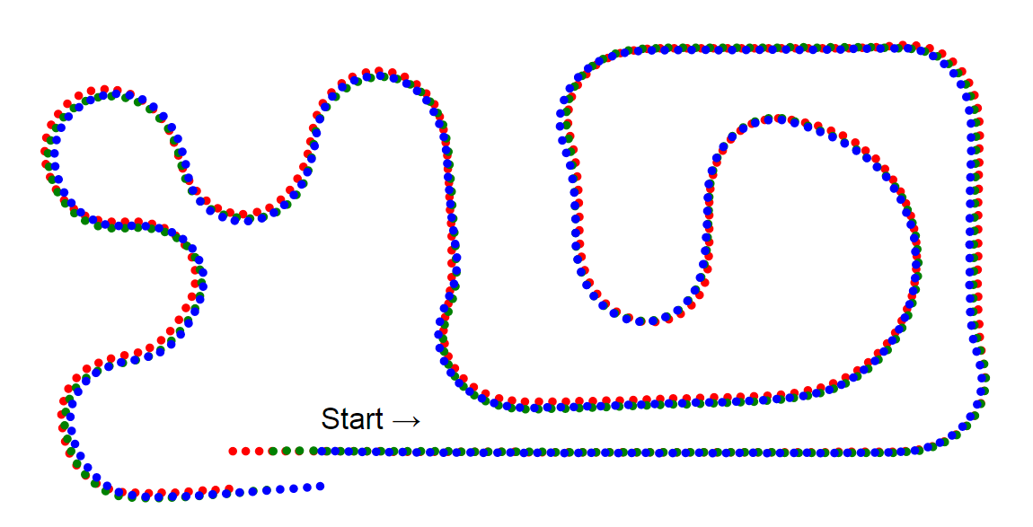 |
Example log data from David’s line follower in 2015, adjusted. |
|---|
So what can be done with all of this information? I can imagine doing some fun things with the data, but this robot only uses it to do two relatively simple things. First of all, on the second and third laps, it uses the data from the first lap to detect when it is on a long straightaway, and increases the motors to their maximum speed if so. This didn’t make much of a difference since the motors were already running at 83%. Secondly, it automatically stops after it has finished the three-lap race so that I can just pick it up instead of having to catch it as it is moving. I was worried that this would backfire on me and the robot would stop before completing the race, but that feature worked correctly 100% of the time during the 5 or 6 times that I ran my robot in the contest.
Just to be clear, a normal line following PID algorithm is in charge of the robot’s movements whenever it is moving; the learning system only serves to notify the PID algorithm of times when it can drive the motors faster. It might be fun to try to turn off the line sensors and navigate the course from memory, but that is not something I attempted.
I definitely recommend using an advanced microcontroller like the one on the mbed if you want to do this kind of learning. LearnBot uses 12 KB of RAM to hold its log, and it was computing sines and cosines very frequently. I don’t think it would be easy to make this work on an 8-bit AVR.
LearnBot is not super fast, and there was no real hope of winning the competition. However, it was fun to write some more advanced firmware to make my line follower a little smarter than the others. For more information, you can see my line following code for the mbed or ask questions in the comment section.
Related products


-
Video: LVBots April 2015 line following competition
- 29 April 2015LVBots held a line following competition at Pololu on April 16th. The goal was to make an autonomous robot that does three laps of the course the...
-
Jon's line following robot: Usain Volt 2.0
- 4 May 2015Like other developers and engineers here, I made a robot for the LVBots Line Following Contest. This post describes my robot, Usain Volt 2.0, and...
10 comments


Our rules are not developed enough to cover that case well. Informally, the robot needs to generally be following the path of the line. It would be nice if we could develop objective criteria for "following the line" that still allows the behavior you are describing.
Ryan


The robot in this post is a custom robot. We do not sell a kit of the parts used in it, but there is a list of most of the components used in this earlier blog post about the robot.
-Claire


There is a link to the code David used in the last sentence of the post.
-Derrill


A 3 degree curve is almost a straight line, so I suspect the behavior of David's code would not be very different in that system. If you want to change how the robot drives for other curves or features on the third lap, you would have to come up with a way of telling when the robot got to that feature and add some your own code to handle it.
-Jon

Also, where does he get the map from, is there some kind of special program or somthing?
I am quite new to coding in general, so i would really apriciate some help.

main function is defined in main.cpp at line 37. I used the
Logger::dump function defined in logger.cpp to format the log data as CSV and send it via USB to a computer. I could have used a spreadsheet program to plot the data, but I wrote a tiny Ruby program (which I have not published) to generate a simple SVG image from it.
Post a comment


Home | Forum | Blog | Support | Ordering Information | Lists | Distributors | BIG Order Form | About | Contact
© 2001–2026 Pololu Corporation

