Voltage Regulators and Power Supplies » Step-Down (Buck) Voltage Regulators » D36V28Fx Step-Down Voltage Regulators »
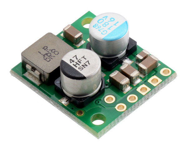
9V, 2.6A Step-Down Voltage Regulator D36V28F9
| Output voltage | Typical max output current1 | Input voltage range2 |
|---|---|---|
| 9 V | 2.6 A | 9.8 V – 50 V |
Note 1: At 36 V in. Actual achievable continuous output current is a function of input voltage and is limited by thermal dissipation. See the output current graphs on the product pages for more information.
Note 2: Minimum input voltage is subject to dropout voltage considerations; see the dropout voltage section of product pages for more information.
Alternatives available with variations in these parameter(s): output type Select variant…
 Compare all products in D36V28Fx Step-Down Voltage Regulators.
| Description | Specs (11) | Pictures (11) | Resources (3) | FAQs (0) | On the blog (1) | Distributors (40) |
|---|
Dimensions
| Size: | 0.7″ × 0.8″ × 0.345″1 |
|---|---|
| Weight: | 3.3 g1 |
General specifications
| Minimum operating voltage: | 9.8 V2 |
|---|---|
| Maximum operating voltage: | 50 V |
| Continuous output current: | 2.6 A3 |
| Output voltage: | 9 V |
| Reverse voltage protection?: | Y4 |
| Maximum quiescent current: | 3 mA5 |
| Output type: | fixed 9V |
Identifying markings
| PCB dev codes: | reg24a, reg24g |
|---|---|
| Other PCB markings: | 0J11946, 0J13687 |
Notes:
- 1
- Without included optional headers.
- 2
- Subject to dropout voltage considerations. See the dropout voltage graph under the description tab for more information.
- 3
- Typical max continuous output current at 36 V in. Actual achievable continuous output current is a function of input voltage and is limited by thermal dissipation. See the output current graph under the description tab for more information.
- 4
- To -40 V. Connecting supplies over 40 V in reverse can damage the device.
- 5
- While enabled with no load. Can be reduced to under 1 mA using the enable pin.


