Electronics » Voltage Regulators and Power Supplies » Shunt Regulators »
Shunt Regulator: 33.0V, 4.10Ω, 15W

This shunt regulator can protect power supplies from voltage spikes generated by motor controllers they are connected to. This version has a fixed set point of 33.0 V, a shunt resistance of 4.10 ohms, and a total of 32 SMT shunt resistors populated on both sides of the PCB (this is the higher-power version). An external potentiometer can also be added to change the set voltage.

| Description | Specs (8) | Pictures (8) | Resources (3) | FAQs (0) | On the blog (1) | Distributors (0) |
|---|
Overview
Most motor controllers encounter scenarios (typically when a motor is slowing down) where energy from a motor is returned to the power supply. That power supply is commonly a battery that can tolerate the current fed into it, and the reverse current can be a welcome “regenerative braking” feature that extends the total life of the battery. For applications that do not involve batteries, however, that reverse current can be a problem when the power supply does not deal with the current well. In some cases, the voltage can build up to a high value that the power supply can tolerate but which might be damaging to the motor controller or other electronics supplied by the power rail. In other scenarios, power supplies have “over-voltage protection” features that detect the output voltage going up and shut down the power supply.
The simplest solution to the problem is often a transient voltage suppressor, or TVS, which is a big zener diode optimized for handling big current spikes. Unfortunately, TVS diodes typically do not have a tight enough tolerance for use with power supplies with overvoltage protection. For example, a 12V power supply might have 5% tolerance, meaning the output voltage could be as high as 12.6V, so the protection device must not kick in below 12.6V. If the over-voltage protection is triggered by a 15% deviation, any voltage spikes must be kept below 13.8V. Most basic TVSes do not have tight enough tolerances to ensure operation in that window.
Pololu’s shunt regulators are designed for such scenarios, with fixed values available with ±3% accuracy for some common voltages, and adjustable versions available to accommodate any voltage from approximately 5V to 35V. To use the shunt regulator, install it across (in parallel with) your power supply. Under normal conditions, the supply voltage should be below the set point of the shunt regulator, and the regulator should only draw its quiescent current of less than 0.5 mA. However, any voltage spikes above the set point will cause the shunt regulator to draw substantially more current, dissipating energy and limiting the extent of the voltage change.
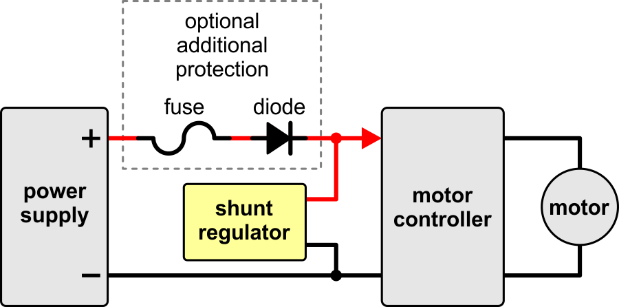 |
Wiring diagram for connecting a Shunt Regulator in a motor controller application. |
|---|
A simplified schematic diagram of the shunt regulator is shown below. Basically, a circuit monitors the voltage and controls a MOSFET that allows current to flow through a shunt resistance that sets the maximum current the device can sink.
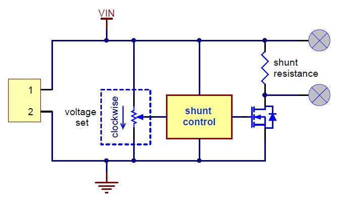 |
Simplified schematic diagram of the Shunt Regulators. |
|---|
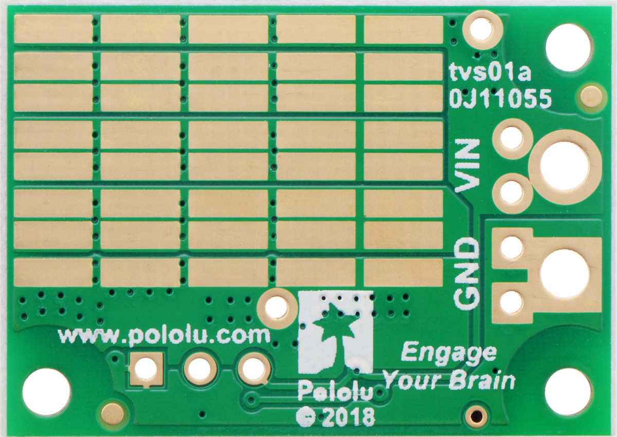
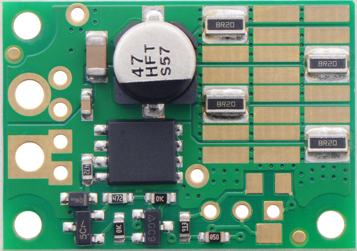
All of the Pololu shunt regulators vary only in the voltage set point and shunt resistance. Available variations include the output type (fixed set point or adjustable via an on-board multi-turn potentiometer), different shunt resistances for the load, and different power ratings for the shunt resistance (the higher-power versions have twenty more resistors populated on the back side of the board).
|
|

One version, the Shunt Regulator: 33.0 V, 32.8Ω, 3W, is populated with an especially high shunt resistance with minimal power rating; this unit is intended for use with an external shunt resistor:
 |
Shunt Regulator: 33.0 V, 32.8Ω, 3W. |
|---|
The available versions are shown in the table below:
| Voltage | ||||||
|---|---|---|---|---|---|---|
| 13.2 V | 26.4 V | 33.0 V | Fine-adjust LV | Fine-adjust HV | ||
| Power | 3 W | – | – | #3780 32.8 Ω |
– | – |
| 9 W | #3770 1.33 Ω |
#3774 4.00 Ω |
#3776 4.00 Ω |
– | – | |
| 15 W | #3771 1.50 Ω |
#3775 2.80 Ω |
#3777 4.10 Ω |
#3778 1.50 Ω |
#3779 4.10 Ω |
|
Note: The power ratings are intended primarily to indicate the relative average power-handling capabilities of the boards for up to a few seconds. The boards are designed for clamping occasional short (up to tens of ms) pulses; continuous application of a voltage above the set point will destroy the regulator almost instantly (in less than a second).
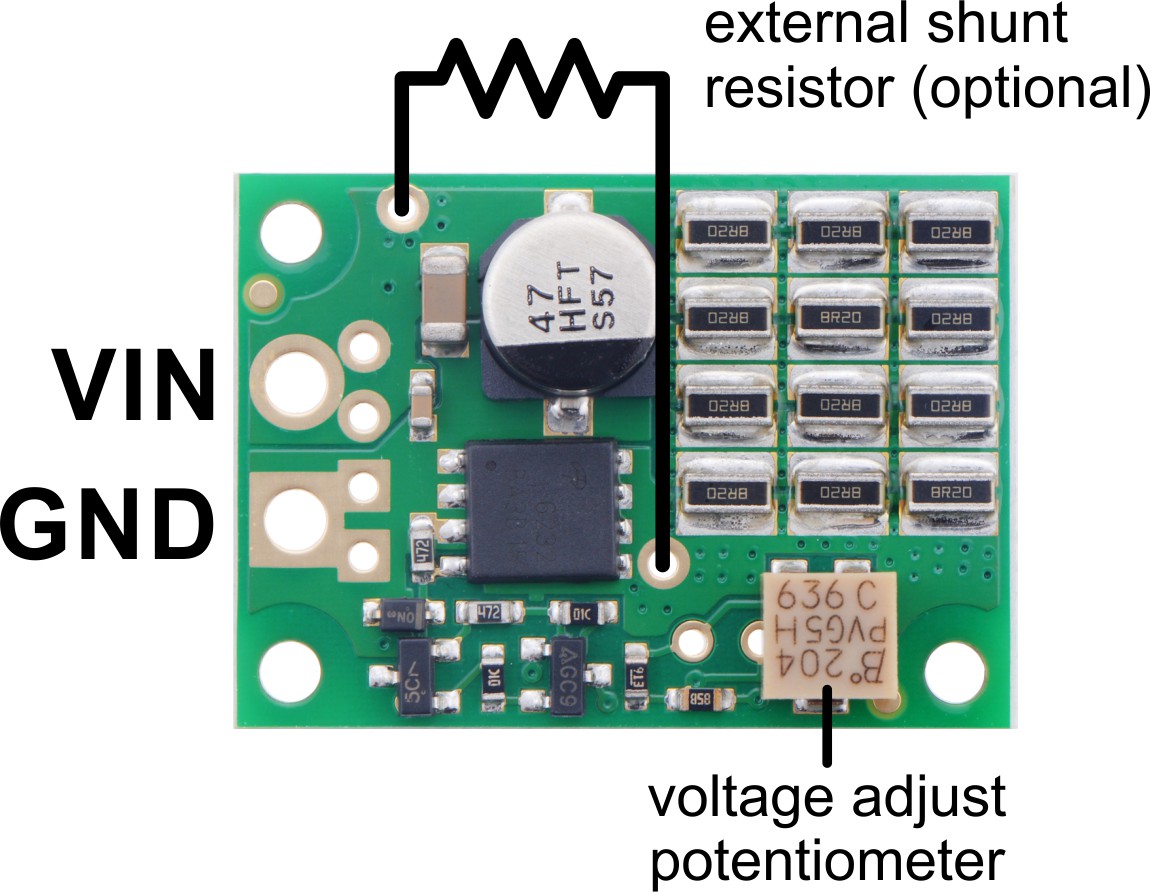
Voltage set point adjustment
The shunt regulator is available in two adjustable versions with multi-turn potentiometers. All of the fixed-voltage versions can also be made adjustable by adding a potentiometer to the board:
|
|

The two adjustable versions vary only in the shunt resistance and in the optimization of the mapping of potentiometer position to voltage set point:
|
|
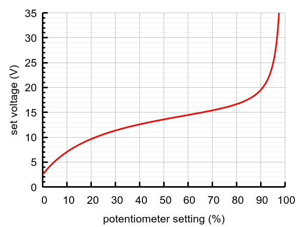

The HV curve is achieved by using a 200kΩ potentiometer with the 33.0V fixed board; using a 200kΩ potentiometer with the lower-voltage fixed boards will distort the mapping to look more like the LV curve. (100kΩ or even lower potentiometers can be used at the expense of higher quiescent current since the full supply voltage gets applied across that potentiometer.)
When setting the voltage with a potentiometer, or to test the exact voltage of any particular shunt regulator, connect a higher voltage through a current-limiting resistor of at least several hundred ohms, and measure the voltage at the regulator. (Without the current-limiting resistor, the shunt regulator would do nothing if it is set higher than your test supply voltage and would go up in smoke if set below your supply voltage!) Typically, you should set your regulator to be about 10% above the supply voltage you are trying to protect.
 |
Wiring diagram for adjusting the set voltage on a Shunt Regulator. |
|---|
Related products


Home | Forum | Blog | Support | Ordering Information | Lists | Distributors | BIG Order Form | About | Contact
© 2001–2026 Pololu Corporation
