Electronics » Sensors » Force-Sensing Resistors and Linear Potentiometers »
Force-Sensing Linear Potentiometer: 1.4″×0.4″ Strip

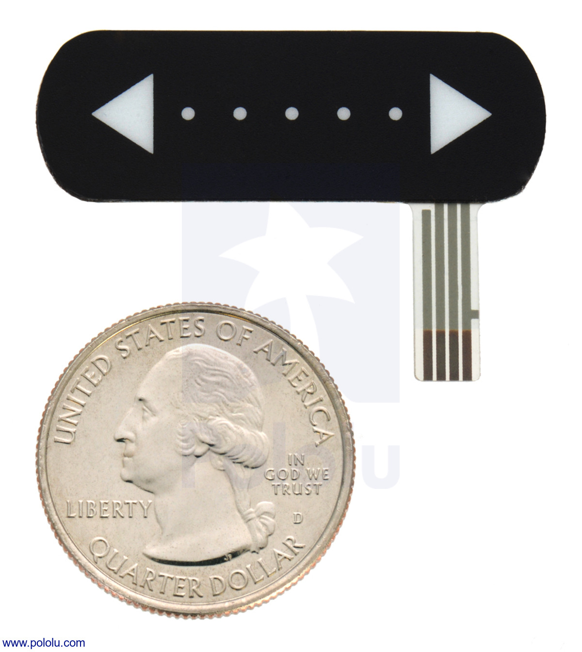
This force-sensing linear potentiometer (FSLP) from Interlink Electronics is a passive component with resistances that depend on the magnitude and location of the force applied at some point along the 1.4″ (3.6 cm) active length of the strip, making it easy to add novel touch interfaces or tactile sensors to your project. An external resistor (typically 4.7 kΩ to 10 kΩ) is required but not included.
 Compare all products in Force-Sensing Resistors and Linear Potentiometers.
| Description | Specs (2) | Pictures (5) | Resources (3) | FAQs (0) | On the blog (1) | Distributors (1) |
|---|
 |
Overview
This force-sensing linear potentiometer (FSLP) from Interlink Electronics is a passive component with internal resistances that independently change in response to the location and magnitude of an applied force. This allows a microcontroller with an analog-to-digital converter (ADC), such as an Arduino or A-Star, to easily determine where and how hard the strip is being pressed, enabling advanced touch-control user interfaces (like menu navigation) or sophisticated tactile sensors. The FSLP is effectively a force-sensing resistor (FSR) that can also simultaneously sense position. The video above shows a sample project with the similar 4″ FSLP strip being used to control an LED strip: position determines the number of lit LEDs and pressure determines the LED color. This shorter 1.4″ FSLP strip could easily be substituted for the one in the video. The Arduino code used in the example is available on github, and it has functions for reading pressure and position that could be helpful in getting started using this sensor. More information about the demo is available in our FSLP blog post.
The 1.5″ × 0.53″ strip is light (0.5 g) and extremely thin (0.025″), with an active sensing area of 1.4″ × 0.39″ and a flexible 0.55″ × 0.2″ sensor tail for accessing its three terminals (the fourth terminal is not used). It does not appreciably compress when pressure is applied, and while it is flexible, it is intended to be used on smooth, flat surfaces since bending can adversely affect its performance. The FSLP has a masked adhesive backing for easy mounting.
Note: The sensor’s tail does not include a connector, and soldering directly to the exposed copper pads is probably not practical for most applications given its relatively fine 1 mm pitch. We do not carry any connectors that work with this sensor, but JST makes a line of compatible 1.0 mm pitch FFC (flat flexible) connectors (188k pdf). Section 4.4 of the FSLP integration guide (513k pdf) describes the sensor tail in detail.
For a similar FSLP that includes a solderable connector, see our 4″ FSLP strip. It is possible to cut the 4″ FSLP strip to shorter lengths, such as 1″, which would give it a similar size to this 1.4″ version.
Note that this FSLP is not a load cell or strain gauge, and it is not suitable for precision force or pressure measurements. While it can be used for high-resolution dynamic measurements, only qualitative force readings are generally attainable.
Using the sensor
 |
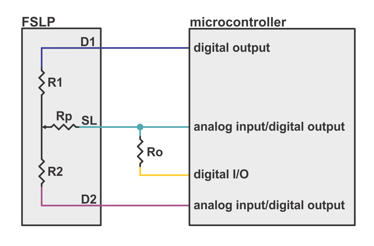
The FSLP is a three-terminal device (the fourth terminal of the sensor tail is not used), and when pressure is applied, its internal circuit is equivalent to three resistors. Reading the magnitude of the pressure requires an external resistor be added to the circuit, so a total of four microcontroller lines are required, two of which must be capable of reading analog voltages. Detailed information about this FSLP, including theory of operation, dimensions, and measurement procedures, is available in the FSLP integration guide (513k pdf). The rest of this section briefly summarizes some of the key points of the measurement procedures listed in the integration guide.
 |
Measuring pressure
The resistance Rp depends directly on the magnitude of the applied pressure, changing from around 300 kΩ at very light touches to around 1 kΩ when pressing very hard. If the pin connected to D1 is driven high and pin connected to the bottom of resistor Ro is driven low, the SL pin becomes the output of a resistive voltage divider with Rp on top and the external resistor Ro on the bottom. Measuring the voltage at terminal D2 gives the input voltage to this pressure-dependent voltage divider and allows the pressure measurement to be made independent of R1 and R2, which change depending on where the strip is being touched. Once you have measured the voltage divider input (D2 voltage) and output (SL voltage), you have everything you need to compute Rp, which is directly related to the pressure.
The optimal value for Ro depends on the specific application, but a value between 4.7 kΩ and 10 kΩ should work fine for most projects.
Note that when no pressure is applied to the strip, Rp should be many megaohms and the voltage at SL will be pulled almost completely to zero through Ro. You can use this to determine when the strip is not being touched.
Measuring position
The strip also functions as a linear potentiometer, with the applied pressure (e.g. your finger) acting as the wiper. As the point of applied pressure moves from one side of the strip to the other, R1 will get smaller and R2 will get bigger, or vice versa (the sum of R1 and R2 is typically around 10 kΩ). If the pin connected to D1 is driven high and the pin connected to D2 is driven low, the SL pin becomes the output of this linear potentiometer (the pin connected to the bottom of Ro should be set as a high-impedance input to effectively remove Ro from the circuit). The voltage on the SL pin should range from 0 to Vcc (logic low to logic high) as the pressure application point moves from one extreme to the other.
Note that when no pressure is applied to the strip, the SL pin is essentially floating and will provide no meaningful position measurement. As described in the previous section, you can use the pressure reading to determine when the strip is not being touched so that you know when to ignore the position measurement.
This sensor has high-impedance outputs, which can be difficult to accurately measure using a microcontroller’s ADC. The full measurement procedures in section 5 of the FSLP integration guide (513k pdf) have some helpful techniques for reducing noise and improving accuracy.
FSLP/FSR versions
Interlink refers to this product as their standard FSLP. We also carry their longer 10 cm (4″×0.4″) FSLP, which can be optionally be shortened to lengths of 1″, 2″, or 3″.
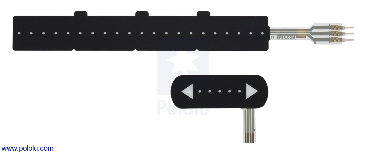 |
The two force-sensing linear potentiometers (FSLPs). |
|---|
If the position of the force is not important for your application, we carry five versions of force-sensing resistors (FSRs) that can be used to measure the amount of applied force but not its location:
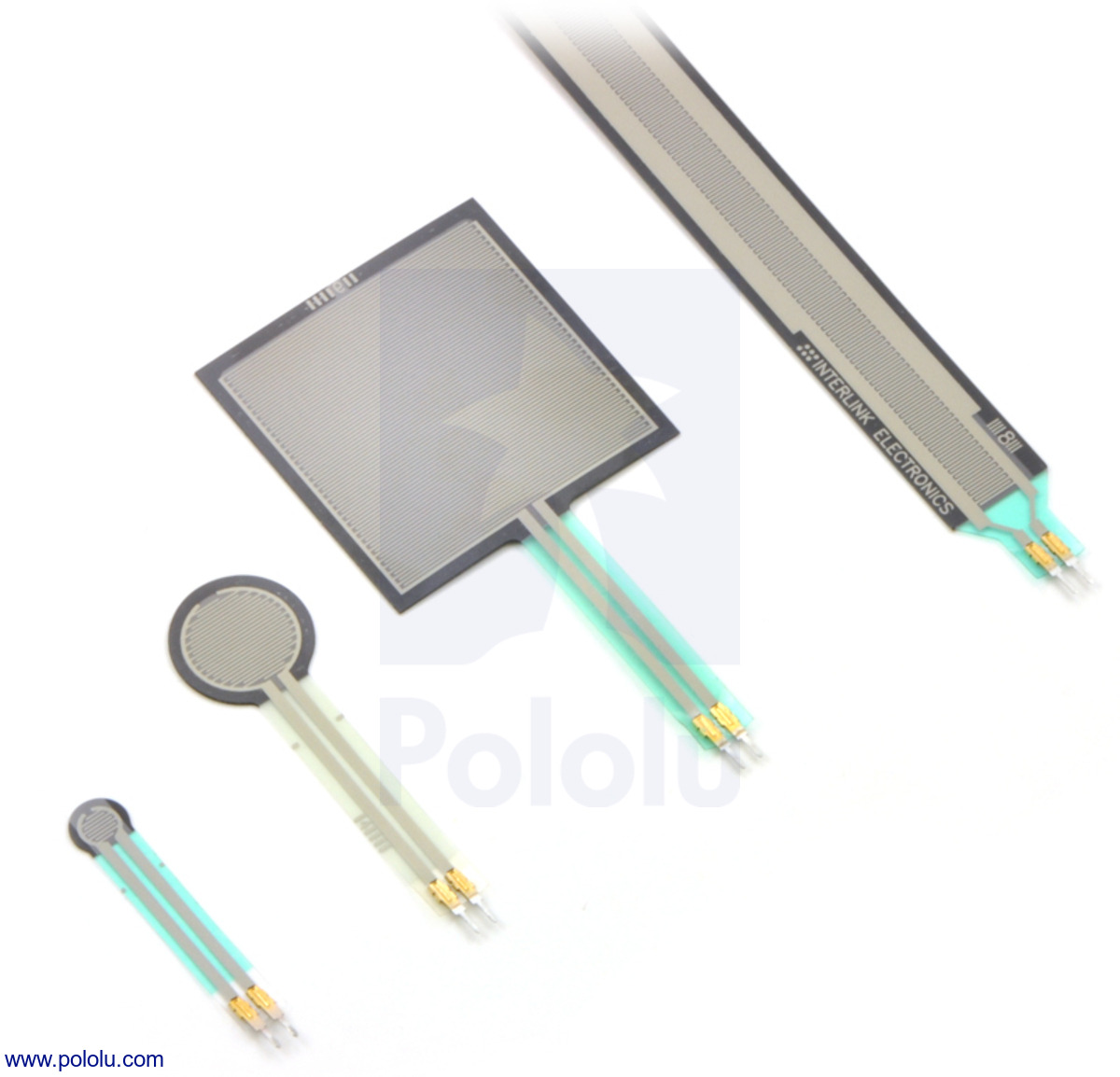 |
A variety of force-sensing resistors (FSRs). |
|---|
- 0.2″-diameter circle (FSR 400)
- 0.25″-diameter circle, short tail (FSR 400 Short)
- 0.6″-diameter circle (FSR 402)
- 0.6″-diameter circle, short tail (FSR 402 Short)
- 1.5″×1.5″ square (FSR 406)
Related products


Home | Forum | Blog | Support | Ordering Information | Lists | Distributors | BIG Order Form | About | Contact
© 2001–2026 Pololu Corporation
