MMA7361LC 3-Axis Accelerometer ±1.5/6g

This tiny triple-axis accelerometer is a basic carrier board for the Freescale MMA7361LC XYZ-axis accelerometer, a great low-g sensor with analog voltage outputs, adjustable sensitivity (±1.5 g or ±6 g), and a 0g-detect digital output that signals when the board is in free-fall. Our breakout board has the form factor of a 10-pin DIP package, which makes it easy to use with standard solderless breadboards and 0.1″ perfboards, and the unit is smaller than competing products, all at a lower price. The board operates from 2.2 to 3.6 V.
Alternatives available with variations in these parameter(s): measurement range Select variant…
| Description | Specs (7) | Pictures (5) | Resources (5) | FAQs (0) | On the blog (0) | Distributors (0) |
|---|
 |
Overview
This tiny three-axis accelerometer is a breakout board for Freescale’s MMA7361LC (177k pdf) and MMA7341LC (177k pdf) MEMS (micro-electro-mechanical systems) low-g accelerometers; we therefore recommend careful reading the appropriate datasheet for your particular board before using this product. The MMA7361 and MMA7341 are great ICs, but their small, leadless packages makes them difficult for the typical student or hobbyist to use. This carrier board includes all of the components in the part’s recommended connection diagram and breaks the pins out to a 0.5″×0.4″ (12.7×10.2 mm) 10-pin DIP form factor that is easy to use with standard solderless breadboards and 0.1″ perfboards.
The two versions of this board provide different sensitivity options: the MMA7361LC carrier offers selectable ±1.5g or ±6g sensitivities and the MMA7341LC carrier offers selectable ±3g or ±9g sensitivities.
Specifications
 |
- Dimensions: 0.4″ × 0.5″ × 0.1″ (without header pins)
- Operating voltage (VDD): 2.2 V to 3.6 V (pins are not 5V-tolerant)
- Supply current: 0.5 mA
- Sleep-mode current draw: < 3 µA
- Output format: 3 analog voltages (one signal for each axis) centered at VDD/2
- Sensitivity range (selectable using g-Select pin):
- MMA7361LC version: ±1.5g (default) or ±6g
- MMA7341LC version: ±3g (default) or ±9g
- Weight without header pins: 0.012 oz (0.35 g)
Using the sensor
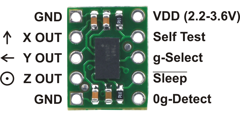 |
The board is powered by supplying 2.2 V to 3.6 V on the VDD pin. Note that this part does not have 5V-tolerant pins, so external components (such as voltage dividers) are required when interfacing the board’s g-Select, Self Test, and Sleep pins with 5V systems. Connections to these pins are optional; the board will work with these pins disconnected as long as the sleep pin is driven high with an on-board solder bridge as described below.
The sleep pin, Sleep, is internally pulled low, which puts the board into low-power sleep mode by default. You must drive this pin high to use the board. This can be accomplished with a microcontroller I/O line if you want selective control of sleep mode, or you can make a solder bridge across the SMT jumper pads labeled “ON” on the silkscreen side of the board to connect the sleep pin to VDD and enable the board by default.
The accelerometer X, Y, and Z outputs are three separate analog voltages centered at VDD/2. Positive accelerations along an axis increase that axis’s output voltage above VDD/2 and negative accelerations decrease the output voltage below VDD/2. The outputs will always be within the range of 0 to VDD.
The sensitivity selection pin, g-Select, is internally pulled low, which selects for a default sensitivity of ±1.5g (800 mV/g) on the MMA7361LC carrier and ±3g (440 mV/g) on the MMA7341LC carrier. Driving the pin high selects for a sensitivity of ±6g (206 mV/g) on the MMA7361LC carrier and ±9g (118 mV/g) on the MMA7341LC carrier.
The 0g-Detect pin outputs high when all three axes simultaneously detect 0g, which happens when the board is in free-fall. This pin is only documented in the datasheet of the more sensitive MMA7361LC IC (the MMA7341LC datasheet labels this pin as “NC”), but we have found that it works on the MMA7341LC at its default ±3g sensitivity. This output does not work at the ±9g sensitivity setting.
The Self Test pin is pulled low on the board and can be left disconnected.
Included components
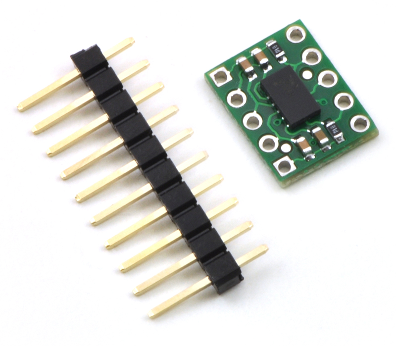
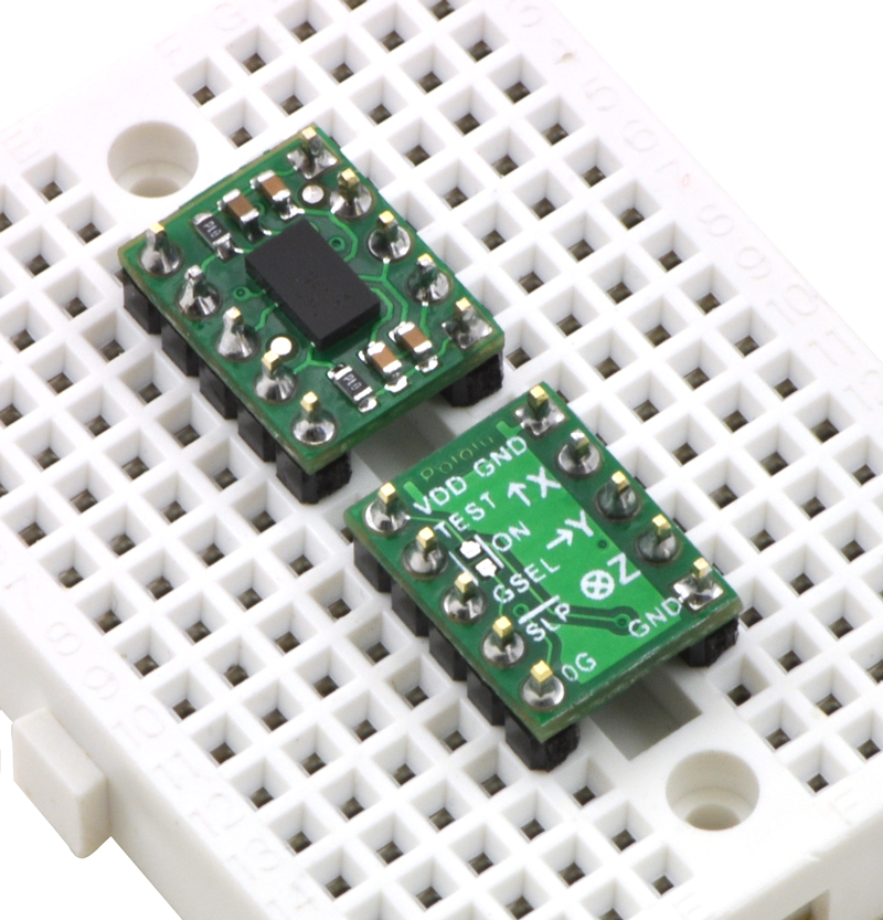
A 10×1 strip of 0.1″ header pins is included, as shown in the left picture below. These pins are not pre-installed. You can break the strip into two 5×1 sub-strips and solder them in to make a 10-pin DIP that can easily be used with solderless breadboards or 0.1″ perfboards, or you can solder wires directly to the board for more compact installations. The right picture below shows the two possible board orientations when used as a 10-pin DIP (parts visible or silkscreen visible).
|
|
Note: Prior to 2012, these boards shipped with older, pin-compatible MMA7361L (175k pdf) and MMA7341L (175k pdf) ICs. The only functional differences between the MMA73x1L and their MMA73x1LC counterparts are a slight change to the tolerance of the zero-g Z output (both MMA7361LC and MMA7341LC) and change in the magnitude of the z-axis self-test response (MMA7341LC only). Revision 2 of the MMA7341LC datasheet also decreased the high-g selectable sensitivity range from ±11g to ±9g, though the corresponding specification of 118 mV/g did not change.
Related products


Home | Forum | Blog | Support | Ordering Information | Lists | Distributors | BIG Order Form | About | Contact
© 2001–2026 Pololu Corporation
