Support »
Pololu Zumo 2040 User’s Guide
View document on multiple pages.
- 1. Overview
- 2. Contacting Pololu
- 3. Assembling the Zumo 2040 kit
- 4. Using the preloaded example programs
- 5. Programming the Zumo with MicroPython
- 6. The Zumo 2040 in detail
- 6.1. Microcontroller
- 6.2. User interface
- 6.3. Motors
- 6.4. Quadrature encoders
- 6.5. Front sensor array (line and proximity sensors)
- 6.6. Proximity sensing
- 6.7. Inertial sensors
- 6.8. Power
- 6.9. Expansion headers and connectors
- 6.10. Pin assignments
- 6.11. Adding electronics
- 6.12. Schematics and dimensions
- 7. Related resources
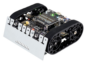
1. Overview
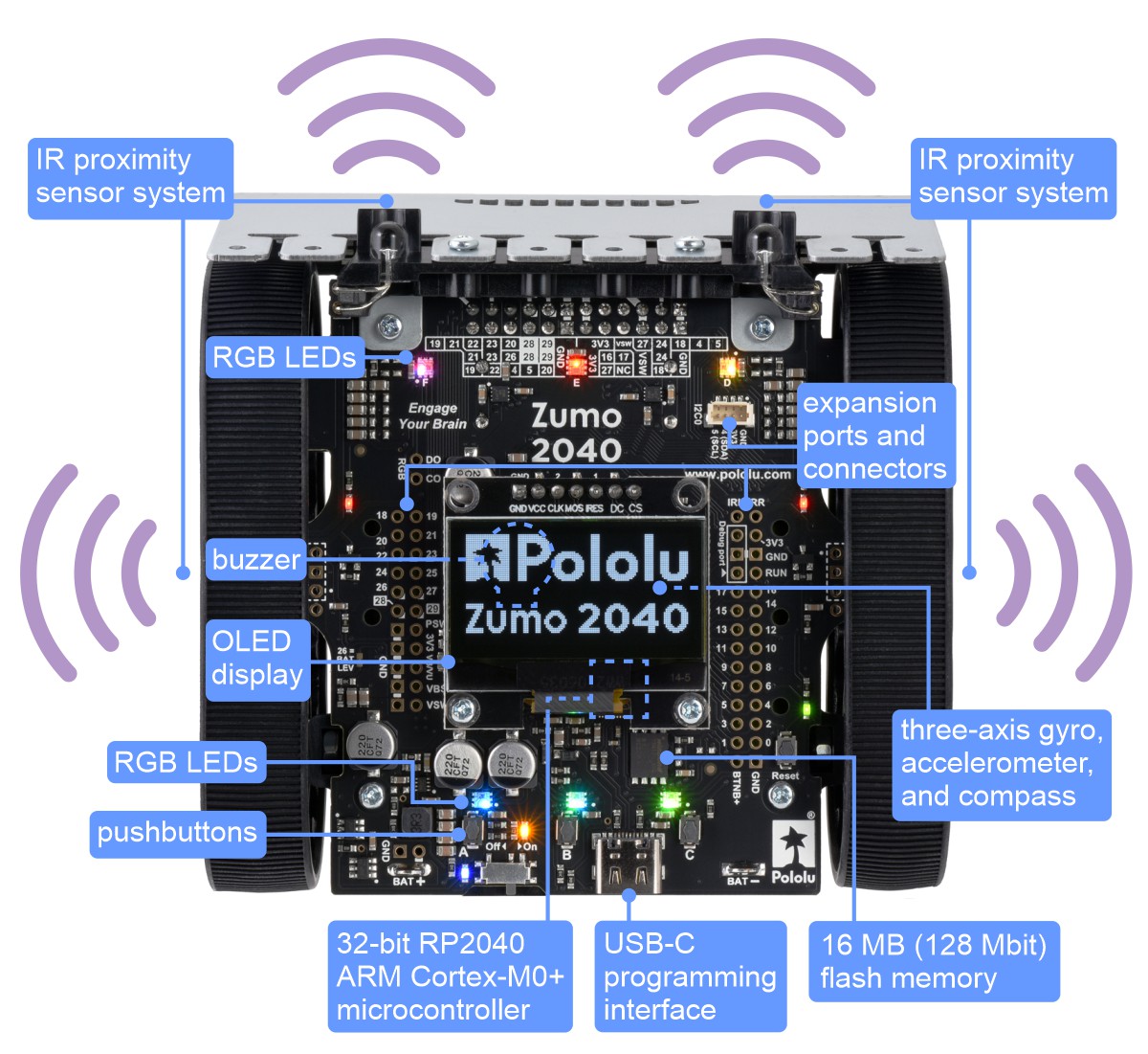
The Zumo 2040 robot is a versatile, high-performance, user-programmable robot. When assembled, the low-profile tracked robot measures less than 10 cm on each side, making it suitable for Mini-Sumo competitions. At its heart is a Raspberry Pi RP2040 microcontroller (like the one on the Raspberry Pi Pico), a 32-bit dual-core Arm Cortex-M0+ processor running at 125 MHz, which can be programmed with C, C++, Arduino, or Python. The Zumo 2040 has 16 MB (128 Mbit) of flash memory that ships preloaded with a MicroPython interpreter, so you can get started right away by plugging into its USB-C port and editing the included example Python programs.
|
|
|
The Zumo 2040 also features two H-bridge motor drivers and a variety of sensors, including a pair of quadrature encoders for closed-loop motor control, a complete inertial measurement unit (3-axis accelerometer, gyro, and magnetometer), reflectance sensors for line following, and proximity sensors for detecting nearby objects. On-board pushbuttons offer a convenient interface for user input, and a 128×64 graphical OLED display, buzzer, and six RGB LEDs allow the robot to provide feedback. For advanced users who want to customize or enhance their robots with additional peripherals, the robot’s power rails, power system controls, and microcontroller’s I/O lines can be accessed via several 0.1″-pitch expansion ports.
 |
 |
1.1. Configurations and included components
The Zumo 2040 robot is available in several configurations:
- Zumo 2040 Robot Kit (No Motors) – requires assembly and soldering; can be customized with your choice of motors (not included)
- Zumo 2040 Robot (assembled with 50:1 HP motors)
- Zumo 2040 Robot (assembled with 75:1 HP motors)
- Zumo 2040 Robot (assembled with 100:1 HP motors)
In addition, the Zumo 2040 Main Board is available separately; it is primarily intended as a replacement part, but you can also use it to make your own Zumo 2040 robot if you do not want all of the parts included with our full kit.
Zumo 2040 robot kit contents
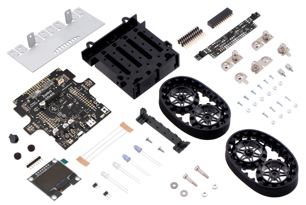 |
Contents of the Zumo 2040 robot kit. |
|---|
The kit version of the Zumo 2040 robot includes the following items:
- Zumo Chassis Kit, which includes:
- Zumo chassis main body
- two drive sprockets
- two idler sprockets
- two 22-tooth silicone tracks
- two shoulder bolts with washers and M3 nuts
- four 1/4″ #2-56 screws and nuts
- battery terminals
- Zumo 2040 Main Board, which includes:
- two 1×2 machine pin sockets for IR LEDs
- buzzer
- 1×7 low-profile male header for OLED display
- jumper wires (for soldering motors to the main board)
- two magnetic encoder discs (12 CPR)
- 2×12 female header for front sensor array
- six 3/16″ #2-56 screws and nuts
- two 1/4″ #2-56 standoffs
- Zumo 2040 Front Sensor Array, which includes:
- 2×12 extended male header for sensor array
- two wide-angle and two narrow-angle through-hole infrared LEDs (these plug into the main board and serve as forward emitters for the proximity sensor detectors located on the front sensor array)
- Zumo Windowed Blade, which includes
- forward IR emitter LED holder
- two 3/16″ #2-28 thread-forming screws for LED holder
- graphical OLED display (the version included with the kit is black)
 |
 |
The robot and chassis kit might include extra parts like jumper wires, screws, nuts, washers, and an acrylic spacer plate (which is not used in the Zumo 2040), so do not be concerned if you have some leftover hardware after assembling your Zumo.
Assembled Zumo 2040 robot
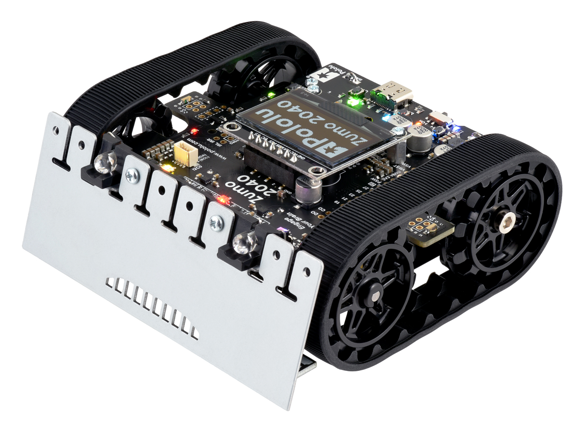 |
The assembled versions of the Zumo 2040 robot are complete, ready-to-program robot platforms built from the same components found in the Zumo 2040 Robot Kit; no soldering or assembly is required. A choice of three motor gear ratios offer different combinations of torque and speed.
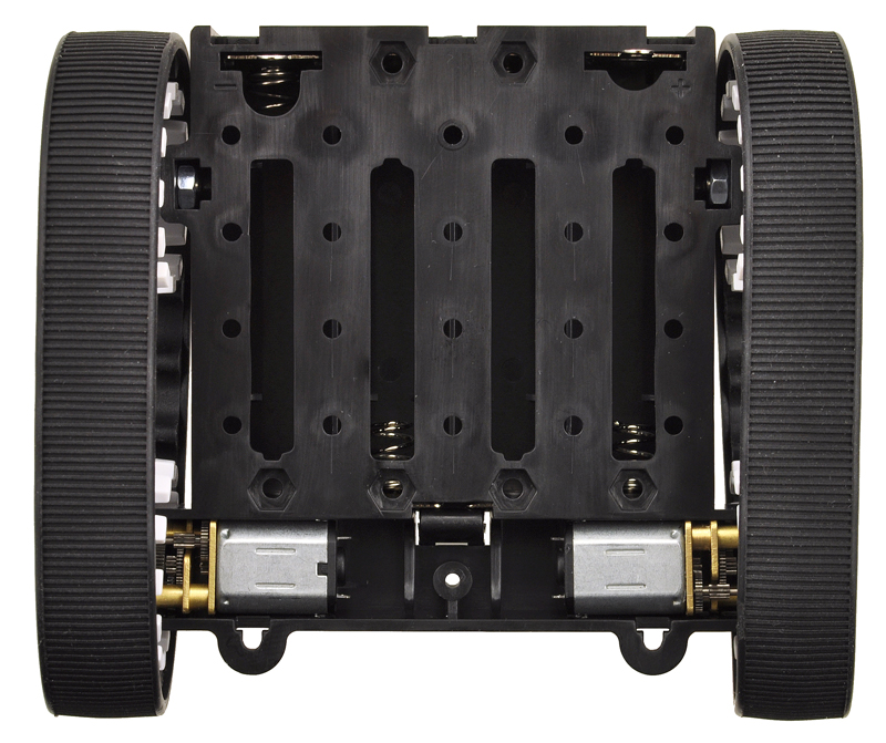
Different versions of the assembled Zumo 2040 robots can be identified with a sticker on the underside of the main board, visible inside the battery compartment of the Zumo without batteries installed. The color of the sticker indicates the gear ratio of the robot’s motors:
- Green: 50:1 HP
- Blue: 75:1 HP
- Red: 100:1 HP
The assembled Zumo 2040 robot is fitted with wide-angle IR emitter LEDs (clear); the narrow-angle LEDs (blue) are not included.
1.2. What you will need
These additional items are needed for using the Zumo 2040 robot:
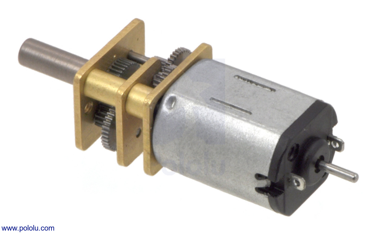 |
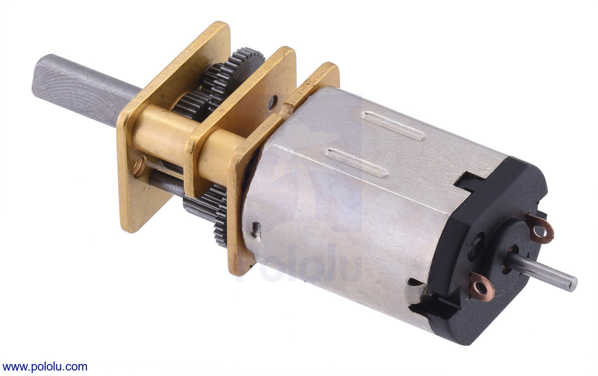
Micro Metal Gearmotor with Extended Motor Shaft. |
|---|
 |
 |
- four AA batteries—the robot works with both alkaline and NiMH batteries, though we recommend using rechargeable AA NiMH cells
- USB-C cable to connect the robot to your computer for programming and debugging
In addition, the kit version of the robot requires:
- two micro metal gearmotors with extended motor shafts (see below)
Kit motor selection
The kit version of the Zumo 2040 robot requires the addition of two micro metal gearmotors with extended motor shafts, one for each tread.
The ideal motors for your robot depend on your desired torque, speed, and current draw. We generally recommend using HP versions of our micro metal gearmotors since the tracks require a decent amount of torque to move effectively; higher gear ratios of the non-HP motors might work if you want lower current draw, but they will be slower and offer less control.
If you are unsure which motors to choose, we recommend getting two of the 75:1 Micro Metal Gearmotor HP with Extended Motor Shaft, which offer a good balance of performance characteristics, and most of our example code was developed and tested with these motors. 50:1 HP and 100:1 HP motors also generally work well. These three motor types are the ones we offer in assembled Zumo 2040 robots.
The following table summarizes the key specifications of the recommended 50:1 HP, 75:1 HP, and 100:1 HP motors. The first four columns are specifications of the motors themselves, while the last column is the measured top speed of a Zumo chassis loaded to a weight of 500 g and driven with these motors. Note that the specifications are for 6V operation, which is approximately the voltage you would get with four fresh alkaline batteries; four NiMH AA cells will typically provide less than 5V.
| Micro Metal Gearmotor |
Free-Run Speed at 6 V |
Stall Extrapolation at 6 V |
Top Zumo Speed at 6 V and 500 g |
|
|---|---|---|---|---|
| 50:1 HP | 625 RPM | 0.86 kg⋅cm, 1.6 A | 1 m/s | (40 in/s) |
| 75:1 HP | 400 RPM | 1.3 kg⋅cm, 1.6 A | 0.65 m/s | (25 in/s) |
| 100:1 HP | 320 RPM | 1.7 kg⋅cm, 1.6 A | 0.5 m/s | (20 in/s) |
For more options, you can see our other micro metal gearmotors with extended motor shafts. Be sure to pick a motor that has an extended shaft, or else you will not be able to use the encoders on the Zumo 2040.
Kit assembly tools
These additional items are needed for assembling the Zumo 2040 robot kit:
- soldering iron and solder (we recommend one with adjustable temperature control)
- wire cutter
- small #1 Phillips screwdriver
- 3 mm Allen wrench (hex key)
- long-nose pliers (for bending the IR LED leads and Zumo blade mounting tabs)
- tape or small clamps (for holding parts together when soldering)
Additional optional components
You might also consider getting these for your Zumo 2040 robot:
- Sensors, such as optical or sonar range finders (the Zumo 2040 already has built-in IR proximity sensors, but additional sensors can be incorporated for increased range or detection area)
- Connectors and jumper wires, for connecting additional sensors and components
- Battery charger, if you are using rechargeable batteries; since the Zumo just uses ordinary AA batteries, we recommend basic AA chargers (into which you stick the individual cells) available at most general electronics stores.
1.3. Supported operating systems
The Zumo 2040 Robot can be programmed from practically any desktop or mobile operating system as long as it has a text editor and the ability to copy files to a USB drive. This includes Windows, Linux, macOS, and ChromeOS.
2. Contacting Pololu
We would be delighted to hear from you about any of your projects and about your experience with the Zumo 2040. You can contact us directly or post on our forum. Tell us what we did well, what we could improve, what you would like to see in the future, or anything else you would like to say!
3. Assembling the Zumo 2040 kit
See Section 1.1 for a diagram to help you identify the contents of the Zumo 2040 robot kit.
Please follow these instructions carefully to assemble your Zumo 2040 robot kit properly. If you have an assembled version of the Zumo 2040 robot, you can skip to Section 5 and start programming it!
Main board additions
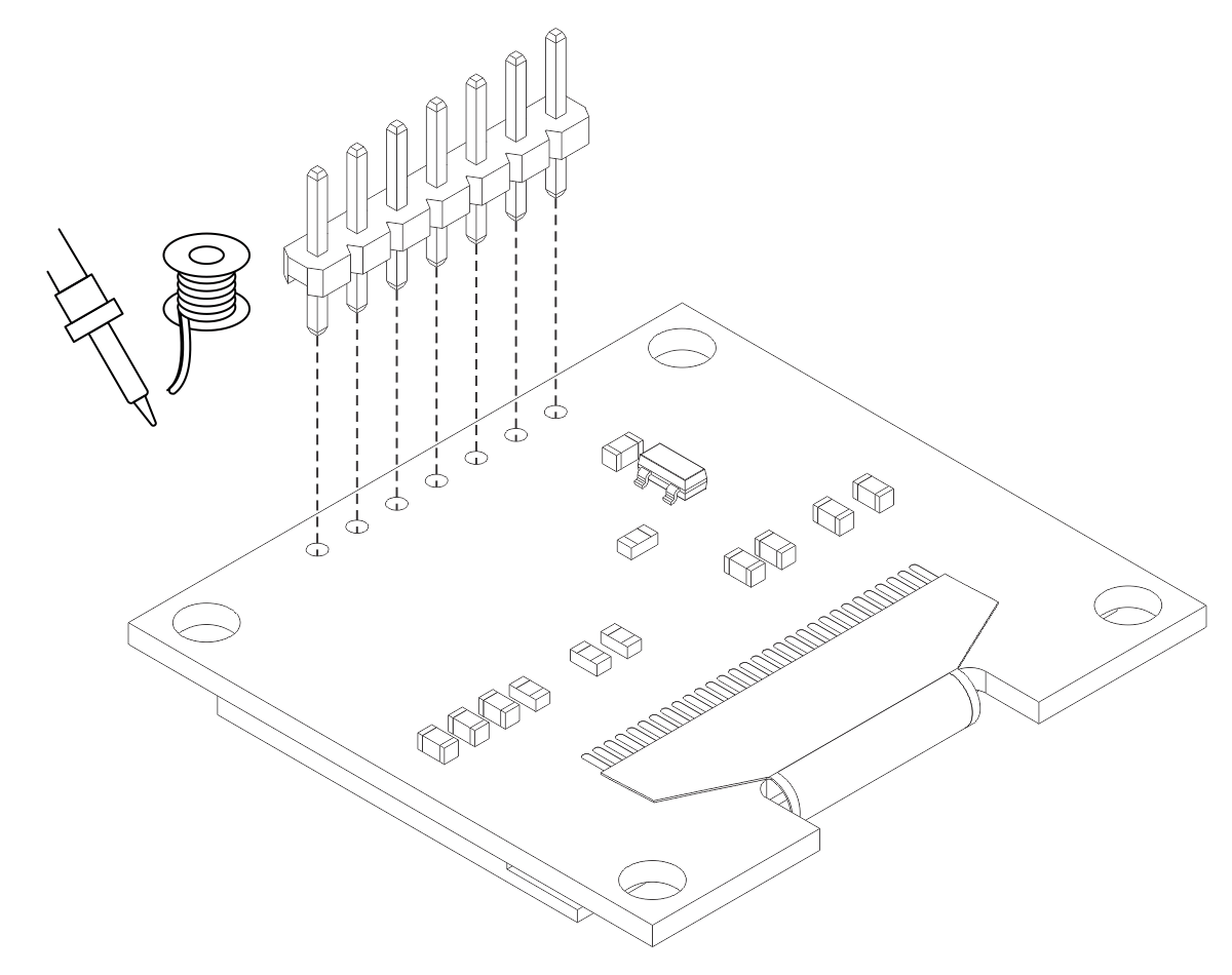
Most of the hardware on the Zumo 2040 main board consists of surface-mount components that are already soldered to the board, but there are a few through-hole parts that you need to solder yourself.
- Solder the buzzer to the top of the main board, matching its orientation to the printed outline on the board, then trim the excess length from the buzzer leads underneath the board.
- Solder the two 1×2 machine pin sockets to the top of the board in the front corners.
- Optional: If you plan to connect headers or wires to the top expansion area, consider soldering them now.
 |
While it is still possible to solder all of these parts after the main board has been mounted on the chassis, soldering them beforehand is easier and avoids the risk of inadvertently melting the chassis with your soldering iron.
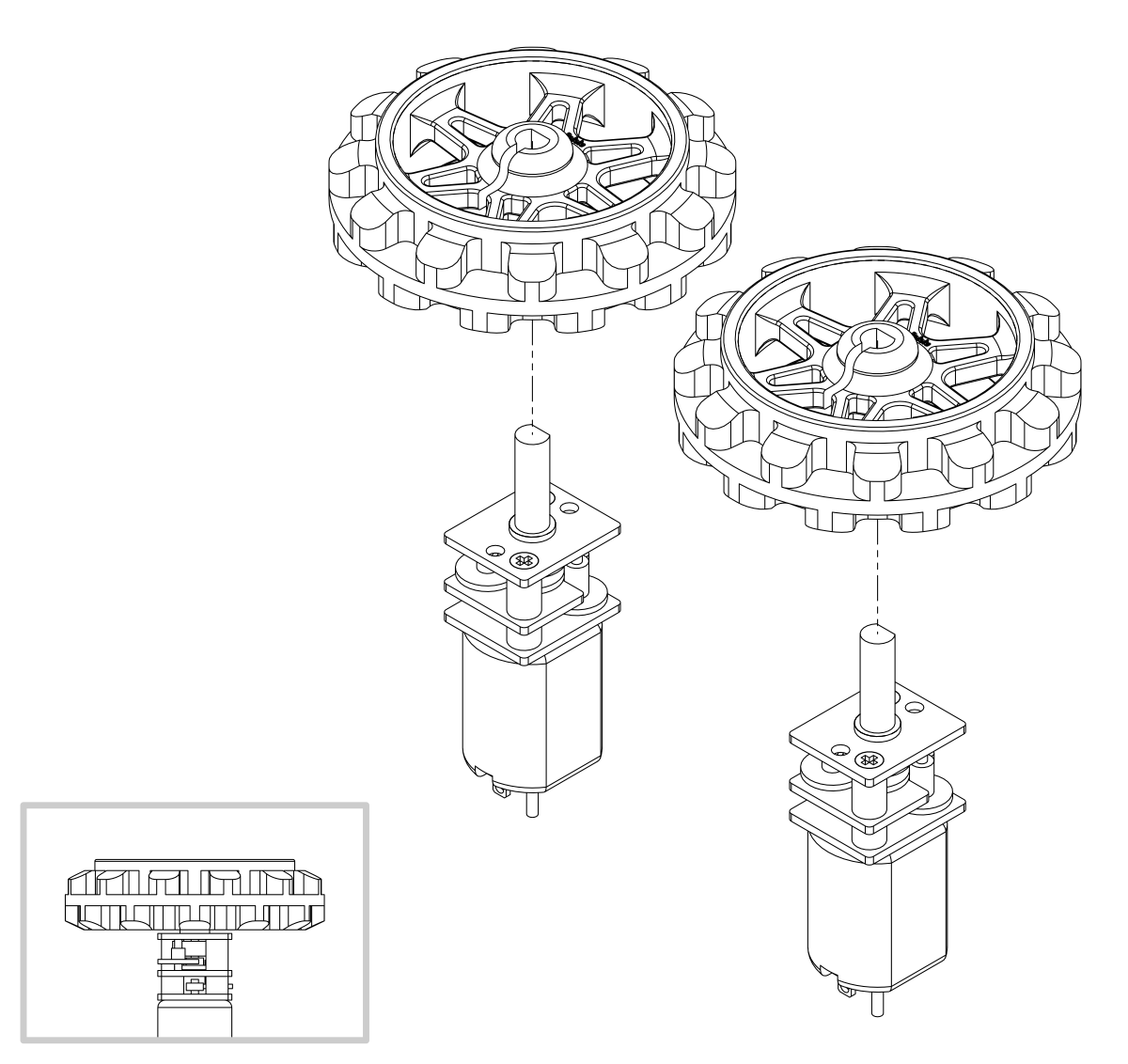
Motors
- Press the output shafts of the motors into the drive sprockets, with the raised lip on one side of the sprocket facing away from the motor. The end of the gearbox shaft should end up flush with the outside of the sprocket. A good way to do this is to set the wheel on flat surface (like a table top) and press the motor shaft into the wheel until it contacts the surface.
 |
- Cut two of the included jumper wires in half to form four segments, and trim off the ends that are covered in adhesive (the adhesive could interfere with making a good electrical connection to the motor). These wire segments will be used as motor leads.
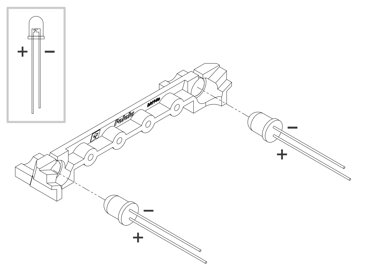
- Solder a pair of leads to each motor, paying attention to the way the motor will eventually be oriented in the chassis (see below). You might find it helpful to make a small bend at the tip of each lead to hook into the hole in the motor lead tab to hold it in place for soldering.
Warning: Holding the soldering iron against the motor lead for more than a few seconds can start to damage the motor brushes, so try to be reasonably quick/efficient with this soldering. If the first attempt does not go well, remove the soldering iron and let the motor cool for a few seconds before trying again.
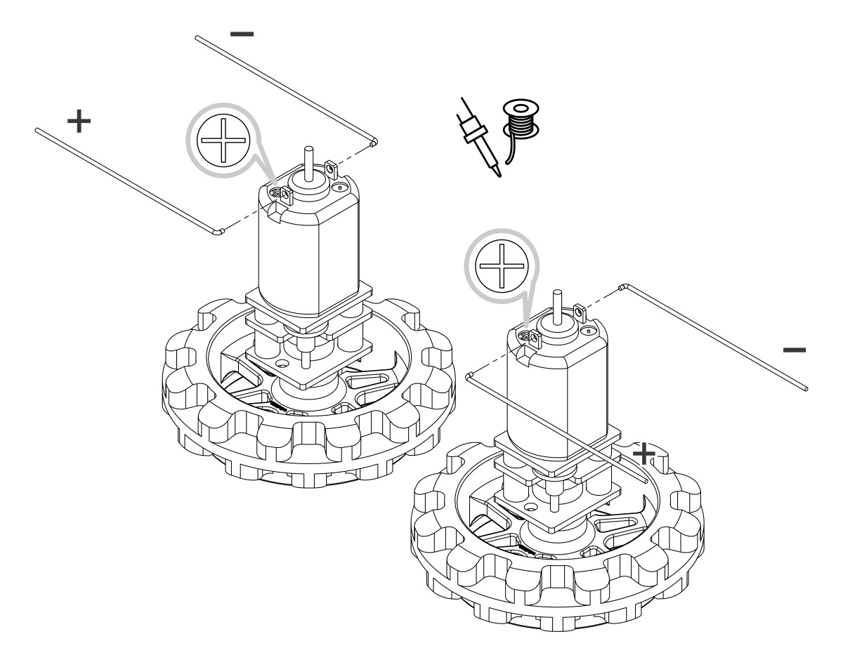 |
Each motor’s positive terminal is indicated by a plus sign (+) in the black plastic end of the motor. If you are using one of our recommended micro metal gearmotors (50:1, 75:1, or 100:1) or any lower gear ratio, the motors should be soldered into the main board with the positive terminal closest to the front, so you should attach the leads to allow the motors to be oriented this way. However, if you are using a motor with a 150:1 or higher gear ratio, you should reverse the motor orientation so the positive terminals are facing the rear. (Don’t worry if you accidentally get the orientation of one or both motors wrong, though. You can later correct for it in software with our library.)
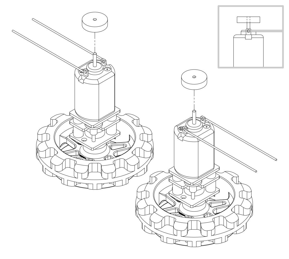
- Press a magnetic encoder disc onto the motor shaft of each motor so that the end of the shaft is flush with the back of the disc. One easy way to accomplish this is to press the motor onto the disc while the disc is sitting on a flat surface, pushing until the shaft makes contact with that surface.
 |
Chassis
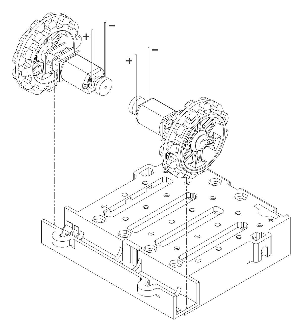
- Place the motors into the channel in the front of the chassis, aligning the gearbox with the grooves in the channel. The outer plate of the gearbox should be even with the edge of the chassis.
 |
- Cover the chassis and motors with the main board. The motor leads should be inserted into the through holes next to the motor drivers.
 |
- Screw the main board to the chassis: we recommend using four screws in the holes closest to the corners of the board. In each of the four mounting holes, insert a #2-56 machine screw through the main board and chassis, and tighten it against a nut under the chassis. It is usually easier to place the nut into the recess first and hold it there with a finger or piece of tape while inserting the screw.
 |
Note that the kit includes two different sizes of #2-56 machine screws: 3/16″ and 1/4″. The two longer screws are intended for use in the front holes (near the motors) so that the additional thickness of a sumo blade can be accommodated. While you can add the blade before screwing the robot together for the first time, we suggest waiting until after you have soldered in the 2×12 connector for the front sensor array so that you have more room to work.
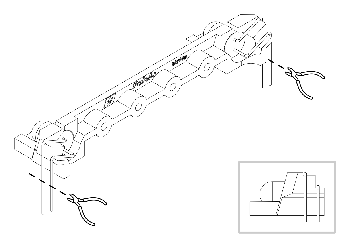
- Solder each motor lead to the main board, then trim off the excess length of wire.
 |
- Solder the 2×12 female header (front sensor array connector) to the bottom of the front expansion area on the main board. It should be flush with the chassis.
 |
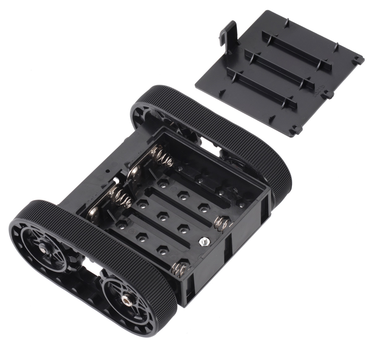
Battery contacts
- Turn the chassis over and install the battery terminal contacts as shown in the pictures below. The three double-contact pieces should be firmly pressed into place until they are flush with the interior surface of the battery compartment.
Note: there are two different kinds of double-sided battery contacts, one with the spring on the left and one with the spring on the right, and they must be installed in the correct locations to make proper contact with the batteries.
 |
The two individual contacts should be inserted into the battery compartment so that their solder tabs protrude through the holes in the top of the chassis; you might want to temporarily tape or clamp these two individual contacts in place until they have been soldered to the main board as described in the next step, or you can use a battery to temporarily hold them in place.
 |
- Solder the two individual contacts to the main board from the top. Note that if you are using a battery to hold the contact in place during soldering, the battery might act as a heat sink, making it more difficult to solder or requiring a higher soldering iron temperature. The battery terminal slot in the PCB should be completely filled with solder.
Idler sprockets and tracks
- Place an M3 nut in each of the two side slots near the rear of the chassis. The slots are sized so that nuts will not be able to rotate within them.
- Place an idler sprocket on each shoulder bolt, followed by a washer. The protruding side of the sprocket hub should face the same direction as the threaded end of the bolt (in toward the chassis).
- Insert the shoulder bolts through the side of the chassis into the nut. Use a 3 mm hex key (Allen wrench) to tighten the bolts until the washers are snug against the chassis. Be careful not to overtighten the shoulder bolts as doing so can bend the washers. Note: Be careful if you use threadlocking adhesives like Loctite as these can corrode the chassis. You should first test any such adhesives on a concealed part of the chassis to ensure they will not damage it.
 |
- Install the silicone tracks by stretching them around the sprockets on each side of the chassis.
 |
Blade
- If necessary, bend the blade’s mounting tabs to the appropriate angle (about 75 degrees from flat).
- Remove the two 1/4″ screws attaching the front of the main board to the chassis.
- Place the blade’s mounting tabs on top of the main board so that the holes line up with the two front mounting holes and the two screws through the blade, main board, and chassis. Replace the nuts underneath the chassis and tighten the screws.
 |
Display
- Solder the 1×7 low-profile header to the OLED display (or the 2×7 low-profile header to the LCD). The shorter side of the header should be inserted fully through the corresponding through holes from the bottom side of the display module until the header is flush, and the solder joints should be made on the top (screen) side of the display. Tip: Solder a single pin first and ensure the header is flush before making any additional solder joints. If the header is not flush, you can use the soldering iron to re-melt the solder joint while you make the necessary adjustments. Be careful not to touch the pin you are soldering as the heat will conduct all the way through to the other end!
 |
- Install two #2-56 standoffs to help support the OLED display. Tighten the standoffs against a nut under the chassis.
 |
- Plug the display into the matching female header on top of the main board; the display should cover the buzzer. Then, use two more 3/16″ #2-56 screw to secure the OLED display to the standoffs.
Warning: The display header does not enforce proper orientation, so it is possible to plug the display in offset or rotated 180° from its intended position. Incorrect positioning can damage the display or the main board, so please take care during this step to ensure that the display is plugged in properly.
 |
Front sensor array
- Solder the 2×12 extended male header to the top of the sensor array. Note: these pins also go on the side of the board without components, so that the sensors point at the ground when the board is plugged into the Zumo; if you solder this header on the wrong side, the sensor array will not work!
 |
- Plug the sensor array into the matching female header on the bottom of the main board.
 |
Forward emitters
- Choose a pair of through-hole infrared LEDs to use as the forward emitters. (See Section 6.6 for details about the different LEDs included with the Zumo 2040.)
- Insert the LEDs into the rear of the LED holder, making sure that each LED’s anode (the longer lead that ends in the smaller post inside the case of the LED) is on the bottom.
 |
- Bend the LED leads outward so they rest along the channels in the LED holder, then downward around the sides of the holder. Using a pair of long-nose pliers can help you make more precise bends.
 |
- Trim the LED leads so that they extend slightly below the bottom of the LED holder.
 |
- Install the LED holder behind the blade by inserting the LED leads into the machine pin sockets in the front of the main board.
 |
- Use two 3/16″ #2-28 thread-forming screws to fasten the LED holder to the blade. Note that the screw heads will not be completely flush against the blade when properly tightened; to avoid damaging the LED holder, do not overtighten the screws!
 |
Batteries
- Install four new or freshly charged AA batteries in the battery compartment. (We recommend using rechargeable AA NiMH cells.)
- Replace the battery compartment cover.
 |
The assembly of your Zumo 2040 robot is now complete, and it is ready to be programmed and run!
 |
4. Using the preloaded example programs
The Zumo 2040 Robot ships with a set of pre-installed programs that demonstrate all of its features. You can try them out without installing any software, and later you can refer to them as programming examples (see Section 5). To get started, just power up the robot. There are two alternative ways to power the Zumo:
- Install four charged AA batteries and slide the power switch to the “On” position. The top blue LED next to the power button will illuminate, and the robot will turn on.
- Connect the robot to USB. The green LED next to the reset button will illuminate, and the robot will turn on automatically.
Note that if you are not using battery power, the motors will not run.
On startup, the Zumo will show this splash screen on its OLED display:
 |
After a few seconds it will switch to the menu of example programs, or you can press button C to proceed to the menu immediately. (On this screen you can also press A to exit the program or B for bootloader mode.)
 |
The menu shows a list of all the Python files installed at the top level of the MicroPython drive. As you can see above, it also tries to show the battery voltage for convenience. With batteries installed and the power circuit on, it should generally show a value of 4.8 V or higher. If batteries are not installed or the power circuit is off, this number will be some low value that doesn’t mean anything.
Navigate up and down the menu with buttons A and C, respectively, and press button B to run the selected file. When you are done with that program, you can press the reset button to restart and return to the menu.
Here is a list of the pre-installed programs:
| File | Description |
|---|---|
| blink.py | Blinks the yellow LED on and off. |
| button_test.py | Lets you type letters with the three pushbuttons. Demonstrates debouncing by using a very slow setting for A: if you tap A twice quickly only the first press will be registered. |
| encoder_test.py | You can gently rotate the wheels by hand to see the wheel encoders measure rotation. For additional feedback, the yellow LED also toggles with each encoder tick. |
| error.py | Simply raises a Python exception. This shows how the built-in menu system helps debugging by emitting a sound and displaying the error on the screen. |
| face_opponent.py | Uses the proximity sensors to locate an opponent robot or any other reflective object and turns to face it. |
| face_uphill.py | Detects slanted surfaces and turns the robot to face uphill. |
| gyro_turn.py | Press A or C to make the robot turn 90° using the gyroscope. |
| i2c0_scan.py | Shows devices detected on I2C bus 0, using pins GP4 and GP5. This will include the on-board IMU sensors and devices you have connected to the expansion ports. |
| imu_test.py | Continuously reads the on-board accelerometer, gyro, and compass and displays all 9 values to the screen. The values are also available with more resolution on the serial terminal. |
| ir_sensor_demo.py | Continuously reads the line sensors, displaying the results as a bar graph. You can press A to calibrate, the robot will start continuously taking calibration readings from its line sensors. Slide the robot across a line, then press A when you are done calibrating. After calibration, press C to switch to calibrated reads for the line sensors. |
| line_follower.py | A PID line follower designed to follow a black line on a white surface. Follow the on-screen instructions to calibrate and start it running. Note that it is intentionally not very well tuned; this is intended as a starting point that you can improve. |
| motor_test.py | Lets you run the left and right motors using buttons A and C. Hold a button to run the motor or tap it to change direction. |
| music.py | Plays a song on the buzzer while blinking the LEDs and displaying the beats and measure numbers. |
| proximity_demo.py | Displays proximity sensor readings as a bar graph. |
| rgb_demo.py | Demonstrates smoothly-changing rainbow effects on the RGB LEDs. |
| rotation_resist.py | Spins the robot to counteract rotation detected by the gyro. Do not move the robot while it says “Calibrating…” on the display. |
| self_test.py | Tests basic functionality of the robot. You can also access this by holding A during startup. |
| siren.py | Demonstrates sound and light effects. |
| spin.py | Runs one motor forward and the other backward to spin the robot in place. Please disconnect your robot from USB for this one, and guard it to prevent it slipping off of a table or otherwise causing damage. |
| sys_info.py | Shows CPU information, the flash serial ID, MicroPython firmware version, and disk/RAM usage. |
You can learn more about these example programs by reading their source code.
5. Programming the Zumo with MicroPython
5.1. Updating the MicroPython firmware
The Zumo 2040 Robot comes preloaded with our custom MicroPython firmware, which you can replace with your own programs or upgrade to a later version of MicroPython.
Checking the installed MicroPython version
Connect the robot to a computer with a USB C cable. If MicroPython is installed on the robot, it should show up as a drive called “MicroPython” that contains Python files:
 |
The dates shown for most of the files and folders will probably correspond to your firmware version, but to check the exact installed version of MicroPython, you will need to connect to the board with a serial terminal program. Here are some general-purpose terminal programs that work with the robot:
- Google Chrome Labs serial terminal – very simple to get started with, web-based, for Chrome, Chromium, or Edge browsers only.
- Tera Term – Windows only.
- PuTTY – cross platform, available for Debian/Ubuntu with apt-get.
- (The Thonny editor that we describe in Section 5.3 also includes a serial terminal, but it requires a few more steps to get started.)
Connect the robot to a computer with a USB cable, run one of these serial terminal programs, and select the correct serial/COM port. Unless you have other serial devices plugged in, this will usually be the only serial port available, and since it’s a virtual serial port, the detailed settings like baud rate do not matter. Once you are connected, press Ctrl+C to exit the running program and Ctrl+B to display the current firmware version. For example, here is what it looks like in the Google Chrome Labs serial terminal:
 |
Connecting to the Zumo 2040 Robot with a serial terminal. |
|---|
In this example, the Zumo is running build 260210-ca86e47, which was released on November 13, 2023 and is a custom edition of MicroPython version 1.27.0, built from commit ca86e47 of our MicroPython build scripts.
Firmware versions
The current release is:
Earlier releases are available on GitHub.
Upgrade instructions
Note: Loading a firmware file will delete all programs and data stored on your robot. Make sure you have anything you are working on backed up before you proceed.
Connect the robot to a computer via a USB C cable. To get the board into bootloader mode, hold down Button B while pressing Reset. (You could also hold down the button while plugging in the cable.) You should see two green lights (VBUS and 3V3) and one or more blue lights indicating power, but nothing else should happen on the Zumo. A drive named RPI-RPI2 should show up on your computer:
 |
There are a couple of files in there you can look at, but this is not a real drive like the MicroPython drive. You can’t store arbitrary data in it. All you can do is drop in a UF2-formatted binary to load that onto the robot’s flash memory.
Download the appropriate firmware file from above, copy it to the drive, and in a few seconds you will have MicroPython installed. The RP2 drive will disconnect and immediately reconnect again, showing our demo programs.
5.2. Editing Python programs
With MicroPython installed on the robot, you can edit files directly on the board in any text editor. To get started, open blink.py on the MicroPython drive:
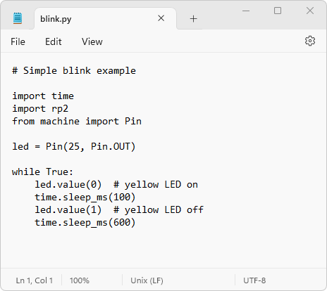 |
The blink.py demo program in a text editor. |
|---|
This program turns the LED on for 100 ms and off for 600 ms, repeating forever. You can run this program from the menu of demo programs as described in Section 4. Make a small change to it, such as replacing the 600 with 100, save the file, and select blink.py from the menu again (you might need to reset the robot to get there.) It will run your updated program with the new blinking pattern.
Now, you can look around at the other files on the board, modify them, make new files, and run any of them from the menu. All of the original demo programs and other files are also available in our GitHub repository.
Note: when editing files directly on the board, keep in mind that it is easy to lose them in various ways:
- Resetting or disconnecting the board while saving a file
- Editing files from within a MicroPython program and from your computer at the same time
- Loading a new firmware file that erases all data
- Software bugs or hardware failure
To avoid losing work, we recommend saving backup copies periodically on your computer.
5.3. Using the Thonny editor
Thonny is a Python editor for beginners that also includes advanced IDE features for editing and debugging code. After you download Thonny and install our plugin as described below, Thonny will recognize the Zumo and help you interact with the MicroPython interpreter running on its control board.
Installing Thonny and connecting to the Zumo
Install the latest version from the Thonny website. Start the program, open the Tools menu, and click “Manage plug-ins…”:
 |
Search for “thonny-pololu”, select the corresponding plugin from PyPi, and click “Install”:
 |
Important: Restart Thonny after installing the plugin. Next, connect your robot to your computer with a USB cable. You should be able to select an option for the Zumo from the interpreter menu in the lower-right corner of Thonny:
 |
Note: If Thonny does not show the “Pololu Zumo 2040 Robot” option here, something is wrong with the plugin install. You can program the board as a Pico or generic RP2040 board, but there will be more confusing options for file loading and saving.
Your currently-running program on the Zumo will stop, and the “Shell” window will show a MicroPython prompt (“REPL”). (If it doesn’t connect or isn’t showing any output, try clicking “Stop” to get connected.)
Using Thonny to interact with the MicroPython interpreter
Next, you can try typing some commands in the Shell window:
 |
If basic commands work, you can try using the hardware on the Zumo:
 |
Next, open the file blink.py from the robot’s drive in the Thonny editor. Assuming you are still connected and see the MicroPython prompt, you can click the green Run button at the top or press F5 to run it immediately. The LED should begin blinking. To stop the program you can press Ctrl+C. Try that now and run the code again with the Run button or F5. Make some modifications and see that the blink pattern changes.
 |
If you save your changes, you will be able to access them from the demo menu system later. To start the demo program, press Ctrl+C (to stop the running program) then Ctrl+D (“soft” reboot).
Upgrading firmware with Thonny
Note: Loading a firmware file will delete all programs and data stored on your robot. Make sure you have anything you are working on backed up before you proceed.
You can also upgrade the MicroPython firmware with Thonny. Get the robot into bootloader mode as described in Section 5.1, and you will see an “Install MicroPython” option in the Thonny’s interpreter menu:
 |
Select this option and then find the appropriate device in the list of variants:
 |
Thonny will automatically download and install our latest firmware version from the Internet.
5.4. Using the Mu editor
Mu is a very simple Python editor. It does not have many configuration options or keyboard shortcuts but is great for basic editing and learning Python. With a small modification described here, Mu can connect to the Zumo 2040 and help you interact with the MicroPython interpreter running on the board.
Install the latest version from the Mu website. Before you run it, locate the install folder (on Windows, this is probably %AppData%\..\Local\Programs\Mu Editor). Search for files named “pico”:
 |
Remove the .pyc file if it exists, and edit pico.py in a text editor. Add a line for the Zumo to the valid_boards section:
    valid_boards = [
        # VID  , PID,    Manufacturer string, Device name
        (0x2E8A, 0x0005, None, "Raspberry Pi Pico"),
        (0x1FFB, 0x2044, None, "Pololu Zumo 2040 Robot"), # <-- add this line
    ]
Start Mu. If it does not immediately identify the board, click “Mode” and choose RP2040 from the menu. Then click REPL to get to the MicroPython prompt. You can try typing some commands there:
 |
Next, open blink.py from the robot’s drive in the Mu editor. Assuming you are still connected and see the MicroPython prompt, you can click the Run button at the top or press F5 to run it immediately. The LED should begin blinking again. To stop the program you can click in the REPL area and press Ctrl+C. Try that now and run the code again with the Run button or F5. Make some modifications and see that the blink pattern changes.
If you save your changes, you will be able to access them from the demo menu system later. To start the demo program, click in the REPL area and press Ctrl+C (to stop the running program) then Ctrl+D (“soft” reboot).
6. The Zumo 2040 in detail
|
|
6.1. Microcontroller
The Zumo 2040 features an integrated Raspberry Pi RP2040 microcontroller, a 32-bit dual-core Arm Cortex-M0+ processor with 264 KB of RAM, clocked with a 12 MHz crystal. This is the same microcontroller and crystal frequency used on the Raspberry Pi Pico. The RP2040 typically runs with a default system clock speed of 125 MHz, although it is rated for a maximum of 133 MHz and can sometimes be pushed even higher.
The main board includes a 16-megabyte (128-megabit) flash memory chip for program storage (non-volatile memory), and this comes preloaded with a MicroPython interpreter and example programs to help you get started quickly. For more information about programming the Zumo 2040 in Python, see Section 5.
The RP2040 has built-in USB support, and the main board has a USB Type-C connector that can be used to connect it to a computer (cable not included). This USB connection can be used to transmit and receive data and program the board over USB. The USB connection can also provide power for the microcontroller and most of the other hardware on the board (but not motor power); see Section 6.8 for more details.
The board also exposes the RP2040’s Serial Wire Debug (SWD) interface, which can be used to interactively debug a program running on the Zumo or to program the flash memory as an alternative to using USB. The debug port consists of two signals, SWDIO and SWCLK, along with a ground pin. These pins are accessible in the Zumo’s top right expansion header; they are labeled on the bottom side of the main board, and SWCLK is indicated with a small white triangle on the top side. To use the SWD interface with a standard desktop or laptop computer, you will need an external device, such as a Raspberry Pi Debug Probe or a Raspberry Pi Pico running the Picoprobe firmware.
6.2. User interface
|
|
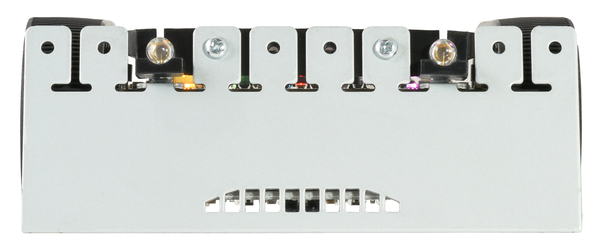
Power switch and pushbuttons
The power switch on the rear of the Zumo 2040 main board controls power from the robot’s batteries.
The main board has four pushbuttons: a reset button on the right and three user pushbuttons located along the rear. Pressing the reset button connects the RUN pin to ground, and pressing one of the user pushbuttons pulls the associated I/O pin to ground through a resistor. The user pushbuttons, labeled A, B, and C, are on GP25, QSPI_SS_N, and GP0, respectively. Button B doubles as a BOOTSEL button to run the RP2040’s built-in USB bootloader if held on startup.
The three buttons’ I/O lines are also used for other purposes: GP0 is a display interface line, GP25 controls the yellow user LED, and QSPI_SS_N is the flash memory chip select pin (in addition to its BOOTSEL function). These uses require the pins to be driven by the RP2040, and reading QSPI_SS_N is not as straightforward as reading a normal GPIO pin. However, resistors in the button circuits ensure that the Zumo 2040 main board will not be damaged and operation will not be disrupted even if the buttons are pressed while the corresponding pins are being driven, and the functions in the Zumo 2040 Robot Libraries and Example Code take care of configuring the pins, reading and debouncing the buttons, and restoring the pins to their original states.
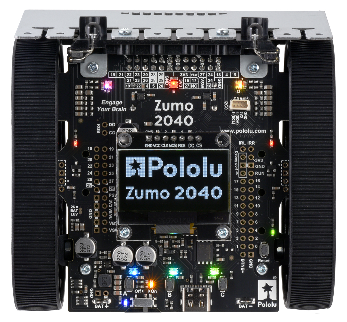
Indicator LEDs
The Zumo 2040 has eight indicator LEDs:
- A yellow user LED is connected to GP25. You can drive this pin low in a user program to turn this LED on. The user LED is located near the USB connector at the rear of the board, and the Zumo 2040 libraries contain functions that make controlling it easier. The user LED shares the GP25 pin with button A.
- Two red LEDs on the left and right edges of the board indicate when the robot’s infrared emitters are active on the corresponding side.
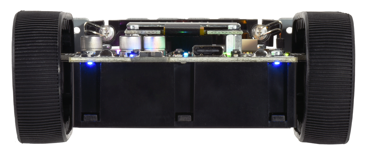
The remaining five LEDs are power indicators:
- A blue power LED next to the power switch indicates when the switch is turned on and the robot is receiving power from its batteries (VSW).
- A blue power LED under the rear left corner of the Zumo (closer to the power switch) indicates when the logic boost regulator is active and producing 8.3 V (VBST). The regulator is powered by the Zumo’s batteries, so the power switch must be turned on.
- A blue power LED under the rear right corner of the Zumo (farther from the power switch) indicates when the Zumo’s 3.3 V logic buck regulator is receiving power (VB/VU). The input to the 3.3 V regulator can come from either the 8.3 V boost regulator or from USB, so this LED will be lit when either the power switch is turned on or when the Zumo is plugged in to USB.
- A green power LED under the center rear edge of the main board (near the USB connector) indicates when the USB bus voltage (VBUS) is present.
- A green power LED on the right edge near the reset button indicates when the Zumo’s logic circuit, including the microcontroller, is receiving 3.3 V power (3V3).
The left blue LED (on VSW) will become noticeably dimmer as the total battery voltage drops below about 3 V, and this can serve as an indication that a set of alkaline batteries has reached the end of its useful life. However, rechargeable batteries can be damaged by overdischarge, so we do not recommend allowing a set of four NiMH cells to discharge to this point. (A voltage divider is connected to GP26 and can be used to monitor the battery voltage; see Section 6.8 for details.)
RGB LEDs
The Zumo 2040 also features six individually-addressable RGB LEDs. Three of these are near the rear of the board by the pushbuttons, while the other three are along the front of the board. The RGB LEDs have integrated drivers compatible with the popular APA102 addressable LED, and they are chained together in alphabetical order (labeled A through F) and arranged counterclockwise on the board.
The main board uses SPI0, one of its two hardware SPI modules, on GP3 and GP6 (TX and SCK, respectively) to control the RGB LEDs. The Zumo 2040 libraries include functions that make it easier to control the RGB LEDs and use them together with the OLED display, which shares the SPI0 interface with the RGB LEDs. The display and RGB LEDs share a common pin for SPI0 TX (data), but use different pins for SPI0 SCK (clock), allowing them to be controlled separately.
The output signals from the last RGB LED are brought out to the DO (data out) and CO (clock out) pins, and you can use these pins to add more APA102-compatible RGB LEDs to the chain.
Buzzer
The buzzer included with the Zumo 2040 can be soldered into the designated through-holes and used to generate simple sounds and music (the buzzer is pre-installed on the assembled versions of the robot). By default, it is connected to GP7, which can be configured as PWM3 B to produce hardware pulse width modulation. If you alternate between driving the buzzer pin high and low at a given frequency, the buzzer will produce sound at that frequency. You can play notes and music with the buzzer using functions in the Zumo 2040 libraries. If you want to use GP7 for an alternate purpose, you can disconnect the buzzer circuit by cutting the surface-mount jumper next to the buzzer.
Display header
The Zumo 2040 main board has a 1×7 header where you can connect a graphical OLED module with a low-profile male header. The kit and assembled versions of the Zumo 2040 robot include an OLED display that has a resolution of 128×64 pixels and uses an SH1106 controller (1MB pdf), which the Zumo communicates with via its SPI0 module.
The Zumo 2040 libraries provide functions to show data on a connected display while also allowing the display interface lines to be used for other purposes (such as pushbutton inputs and RGB LED data).
6.3. Motors
The Zumo 2040 robot is available with three different motor options:
| Micro Metal Gearmotor |
Free-Run Speed at 6 V |
Stall Extrapolation at 6 V |
Top Zumo Speed at 6 V and 500 g |
|
|---|---|---|---|---|
| 50:1 HP | 625 RPM | 0.86 kg⋅cm, 1.6 A | 1 m/s | (40 in/s) |
| 75:1 HP | 400 RPM | 1.3 kg⋅cm, 1.6 A | 0.65 m/s | (25 in/s) |
| 100:1 HP | 320 RPM | 1.7 kg⋅cm, 1.6 A | 0.5 m/s | (20 in/s) |
You can also assemble the Zumo kit with different motor and gear ratio combinations to make your own custom Zumo 2040 robot. Section 1.2 discusses some things to consider when choosing motors.
 |
Two on-board motor drivers power the Zumo 2040’s two Micro Metal Gearmotors. Four GPIO pins are used to control the drivers:
- GP10 controls the right motor direction.
- GP11 controls the left motor direction.
- GP14 controls the right motor speed with PWM (pulse width modulation) generated by the RP2040’s PWM7 A channel.
- GP15 controls the left motor speed with PWM generated by the PWM7 B channel.
The Zumo 2040 Robot Libraries and Example Code provide functions that allow you to easily control the motors, and it can optionally take care of flipping a direction signal for you if you accidentally soldered in a motor backwards or are using a gear ratio with an odd number of stages, so the output turns the opposite direction from the input.
As your batteries run out, the voltage supplied to the motor drivers (VSW) will decrease, which will make the motors slower. It is possible to account for this in your code by monitoring the battery voltage (see Section 6.8) or using the encoders and other sensors to monitor the movement of the robot.
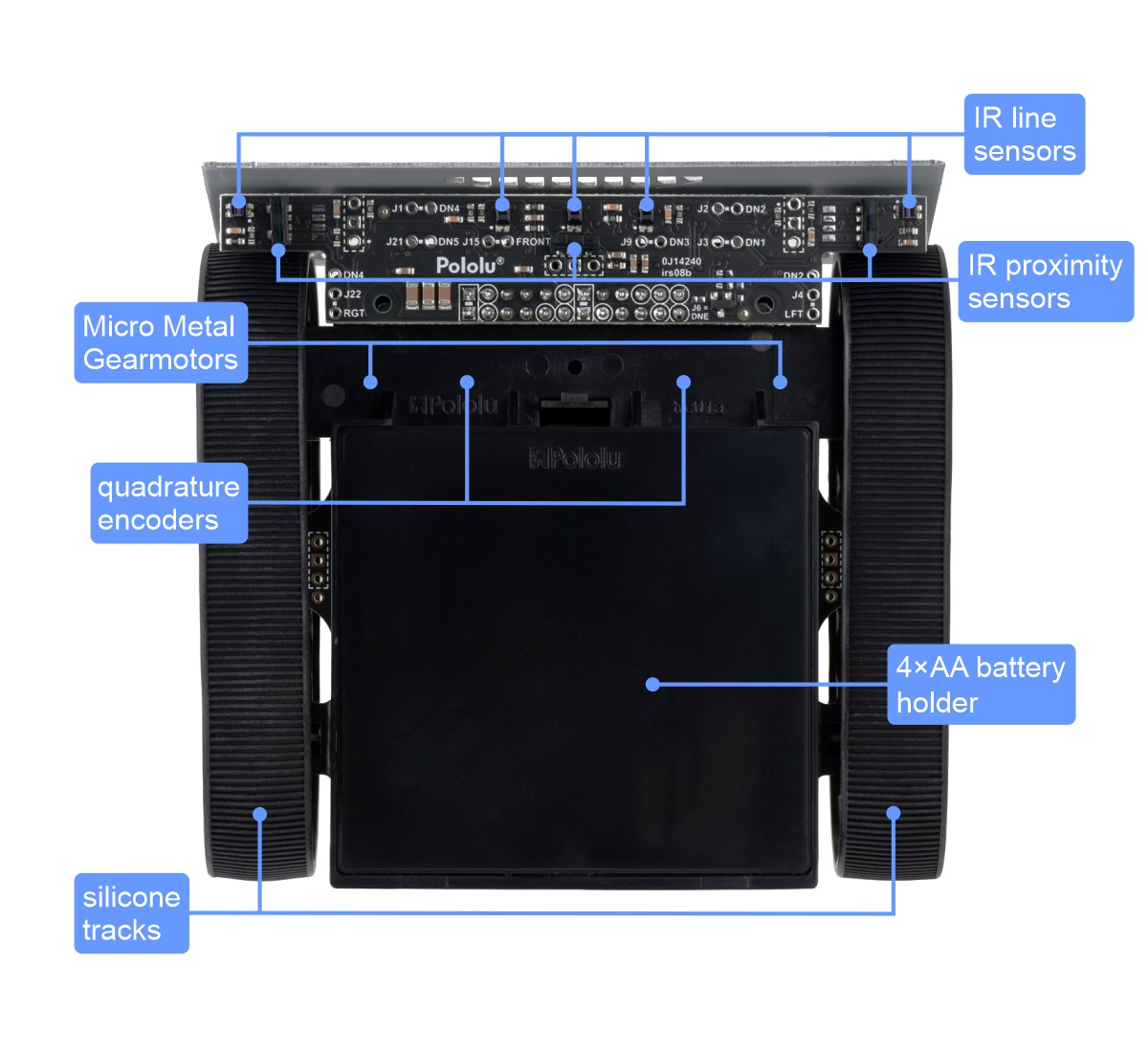
6.4. Quadrature encoders
Each drive motor on the Zumo 2040 has a corresponding quadrature encoder system consisting of a magnetic disc attached to the extended motor shaft and a pair of Hall effect sensors mounted on the main board. Other than the sensor orientation, these encoders work similarly to our magnetic encoder kits for Micro Metal Gearmotors. They can be used to track the rotational speed and direction of the robot’s wheels.
The encoders provide a resolution of 12 counts per revolution of the motor shaft when counting both edges of both channels. To compute the counts per revolution of a wheel, multiply the motor’s gear ratio by 12. For example, if 75:1 motors (which have gear ratios more accurately specified as 75.81:1) are used, the encoders provide 75.81 × 12 ≈ 909.7 CPR. The exact gear ratios of our Micro Metal Gearmotors are specified on their product pages.
Four GPIO pins are used to read the encoders:
- GP8 reads the right encoder channel A.
- GP9 reads the right encoder channel B.
- GP12 reads the left encoder channel A.
- GP13 reads the left encoder channel B.
For both encoders, channel B leads channel A when the motor is rotating in the forward direction; that is, B rises before A rises and B falls before A falls.
The Zumo 2040 Robot Libraries and Example Code provide appropriate functions for reading the encoders and keeping track of their counts.
6.5. Front sensor array (line and proximity sensors)
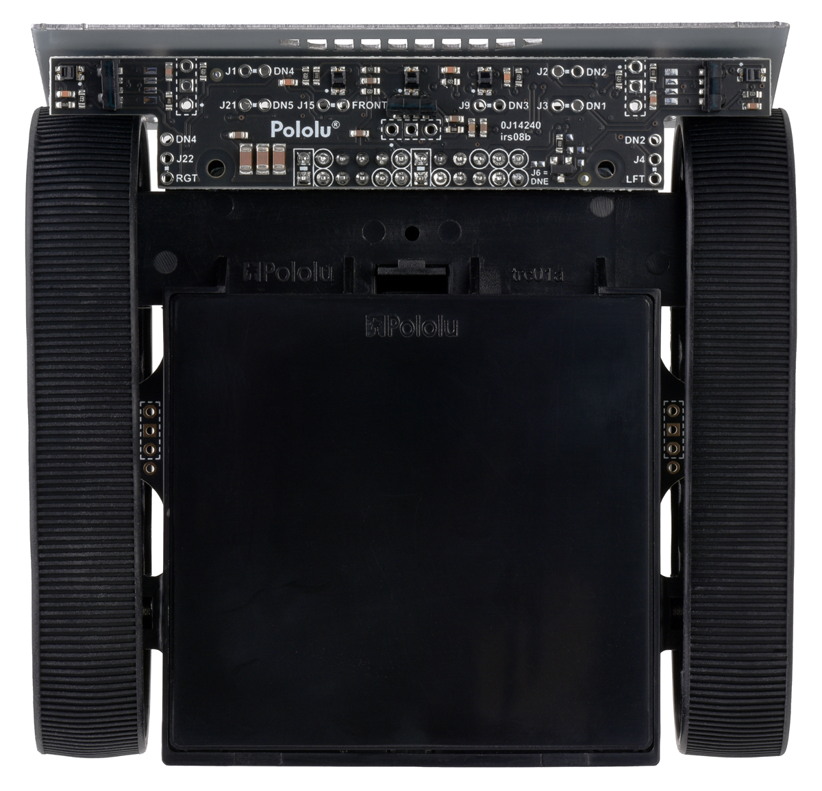 |
The Zumo 2040 Front Sensor Array is a separate board that attaches to the main board. The board features five line sensors and three proximity sensors.
The five line sensors face downward and can help the Zumo distinguish between light and dark surfaces. Each reflectance sensor consists of a down-facing infrared (IR) emitter LED paired with a phototransistor that can detect reflected infrared light from the LED. The reflectance sensors operate on the same principles as our RC-type QTR reflectance sensors: the RP2040 uses an I/O line to drive the sensor output high, and then measures the time for the output voltage to decay. You can read more about the operating principles of these sensors in our QTR Reflectance Sensor Application Note.
The five line sensors are numbered 1 through 5, with line sensor 1 being the robot’s left-most sensor. In schematics and diagrams, they are referred to as DOWN1, DOWN2, DOWN3, DOWN4, and DOWN5. On the front sensor array, their signals are labeled DN1, DN2, DN3, DN4, and DN5. The infrared emitters for the line sensors are controlled by the DOWNEMIT signal, which is labeled DNE on the front sensor board.
The three proximity sensors face in different directions away from the Zumo and can help detect nearby objects. They can also be used to detect commands from typical IR remote controls. The proximity sensors, like the line sensors, detect reflected IR light, but they are designed to only detect light that is turned on and off quickly at a frequency of 56 kHz. To read a proximity sensor, the RP2040 can enable the internal pull-up on the corresponding I/O line. When the sensor is active, it will drive the line low. The proximity sensors do not have IR emitters paired with them; instead they detect reflected 56 kHz IR light that comes from LEDs on the Zumo 2040 Main Board, which are described in Section 6.6. The proximity sensors are named after the directions they face: left, right, or front. In schematics and diagrams, they are referred to as LEFT, RIGHT, and FRONT. On the front sensor array, their signals are labeled LFT, FRONT, and RGT.
Each sensor output on the front sensor array is protected by a 220 Ω resistor to help prevent short circuits when the RP2040 is driving the corresponding I/O line.
The infrared light emitted by the line sensors can interfere with the proximity sensors and cause false readings, so it is recommended to turn off the line sensor emitters before using the proximity sensors.
The Zumo 2040 Robot Libraries and Example Code provide functions to help with reading the line sensors and proximity sensors, and it handles control of the emitters appropriately.
Ambient light considerations
Since the line sensors and proximity sensors rely on measurements of reflected infrared light, they are strongly affected by ambient sources of IR light in the surrounding environment (e.g. sunlight or strong incandescent lighting).
You can help compensate for ambient IR light by incorporating some calibration procedures in your programs. For example, the line sensors can measure the reflectance of light and dark surfaces during calibration and then report subsequent readings relative to this range. The Zumo 2040 libraries provide support for calibrating the line sensors in this way.
However, this calibration is not foolproof; too much ambient infrared light can still prevent the line sensors from working well, and the calibration will not remain effective if the ambient light level changes, such as if the Zumo moves from a brightly lit area to a more shaded area.
Pin assignments and remapping
By default, the front sensor array supports these pin assignments:
- GP26 is connected to the line sensor emitter control pin (DNE).
- GP22 is connected to line sensor 1 (DN1).
- GP21 is connected to line sensor 2 (DN2).
- GP20 is connected to line sensor 3 (DN3).
- GP19 is connected to line sensor 4 (DN4).
- GP18 is connected to line sensor 5 (DN5).
- GP27 is connected to the front proximity sensor.
- GP23 is connected to the left proximity sensor.
- GP24 is connected to the right proximity sensor.
GP26 also doubles as an input to measure the battery level through a voltage divider (see Section 6.7), which uses a ratio low enough that the line sensor emitters will effectively be off while the pin is an input.
The signals from the sensors can be remapped by soldering in a wire from the signal output to the desired GPIO pin. You would also want to disconnect the sensor output from the default GPIO pin so that pin can be used for other purposes. Disconnecting each sensor involves cutting a trace between the signal output and the default GPIO pin, which is labeled according to the position of its pin on the front sensor board’s connector. (For example, line sensor 1 is connected to pin J3, which plugs into GP22 on the Zumo main board.)
GP17 and GP16 are also used for proximity sensing as they respectively control the left and right proximity emitters on the Zumo’s main board, although these two pins do not interface with anything on the front sensor array.
6.6. Proximity sensing
The Zumo 2040 can detect nearby objects using the three proximity sensors on the front sensor array. The proximity sensors do not emit their own light; instead they are designed to detect 56 kHz infrared (IR) signals from emitters on the Zumo 2040 Main Board.
The main board has four IR emitters:
- The middle-left and middle-right IR LEDs are surface-mounted on either side of the Zumo, inside the tracks and between the wheels. They emit light to the left and to the right.
- The front-left and front-right IR LEDs are meant to face towards the front, though you can play with the exact angle to see if it yields better results for your particular application. In the Zumo 2040 kit, these LEDs are included but must be installed by the user, as described in Section 3.
The middle-left LED and the front-left LED are in series, so you must install the front-left LED in order to use the middle-left LED, and you cannot turn on one without turning on the other. Similarly, the middle-right and front-right IR emitters are in series.
Two RP2040 pins are used to control the LEDs with PWM (pulse width modulation): GP17 controls the left proximity LEDs, and GP16 controls the right LEDs. The LEDs turn on when their corresponding control pin is high, and the brightness of the emitters can be controlled by adjusting the duty cycle of the PWM signal on the control pin. It is possible to enable the emitters on both sides at the same time, but alternating sides is usually better as it allows the Zumo to compare the readings obtained with each set of emitters.
Our example code operates the proximity sensors by transmitting pulses on the left and then the right LEDs at six different brightness levels. For each sensor, it generates two numbers: the number of brightness levels for the left LEDs that activated the sensor, and the number of brightness levels for the right LEDs that activated the sensor. A higher reading corresponds to more IR light getting reflected to the sensor, which is influenced by the size, reflectivity, proximity, and location of nearby objects. However, the presence of other sources of 56 kHz IR pulses (e.g. from another robot) can also affect the readings; even other frequencies or constant IR light can sometimes influence the sensors.
You can also just read the proximity sensors without turning on any LEDs. This could allow the Zumo to detect the IR proximity sensors of other robots, or to detect commands from a typical IR remote.
Forward LED selection
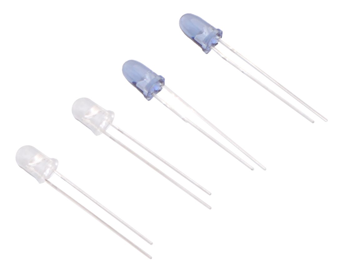 |
The kit version of the Zumo 2040 comes with two types of through-hole IR LEDs that can be installed to serve as the forward emitters. Both types of LEDs use the T-1 3/4 package, meaning they have a diameter of approximately 5 mm. Also, they both emit 940 nm light. The main difference between these LEDs is their viewing angle. The blue-colored LEDs have a relatively narrow viewing angle of 20°, which makes them better at illuminating objects far away. The clear LEDs have a much wider 50° viewing angle, which makes them better at illuminating objects that are not directly in front of the Zumo. The choice of IR LEDs to use is one way for you to customize your Zumo.
The assembled versions of the Zumo 2040 robot ship with clear (wide-angle) LEDs installed; blue (narrow-angle) LEDs are not included with these versions.
IR LED holder
Proper shielding for the forward emitters is important; without shielding, light from the LEDs can activate the proximity sensors directly and cause false readings. The Zumo 2040 comes with a plastic LED holder that serves to shield the LEDs while also holding them in place and helping to protect them from collisions with other robots. The LED holder screws to the blade with the two included 3/16″ #2-28 thread-forming screws. See the assembly instructions in Section 3 to learn how to properly install the forward emitters with the LED holder.
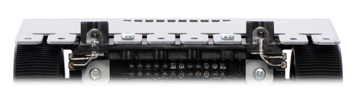 |
IR LEDs with LED holder. |
|---|
Shielding with heat shrink tubing
You can make shrouds out of black heat shrink tubing to shield the forward emitters as an alternative to using the LED holder. Without the LED holder, the LEDs are less securely mounted, but you can more easily adjust their positioning.
 |
IR LEDs with heat shrink shielding. |
|---|
You can test to see if your shielding is good by putting your Zumo on a black surface with no objects nearby and making sure that you get a reading of 0 for all the proximity sensors.
3/16″ diameter heat shrink tubing can work well, but please note that the actual diameter of heat shrink tubing often differs significantly from its nominal diameter, depending on the type and manufacturer of the tubing.
Proximity sensor performance
The proximity sensors have no particular minimum sensing distance; they can sense an object that is close to the Zumo as long as the shape of that object allows some light from the LEDs to be reflected into the sensor.
The maximum sensing distance depends on the size and reflectivity of the object you are sensing. We did several tests of the front proximity sensors to see how well they could see the steel blade of another Zumo while both robots were on the black surface of a sumo ring. In these tests, we found that the maximum sensing distance was around 30 cm to 40 cm.
There is a significant dead spot between the sensing regions of the front sensor and each side sensor. Therefore, if the Zumo senses an object with the left or right sensors and then turns to face it, there will probably be a period of time where none of the sensors can see the object.
Facing towards an object
The example Python program face_opponent.py found in the Zumo 2040 Robot Libraries and Example Code uses the motors and the proximity sensors to scan for nearby objects, face directly towards them, and track them if they move. To directly face an object, it compares two sets of readings from the sensor: the number of brightness levels for the left LEDs that resulted in the left or front sensor activating, and the number of brightness levels for the right LEDs that resulted in the right or front sensor activating. If the left reading is greater than the right reading, it means the object is closer to the left LEDs, so the robot should turn left (counter-clockwise) to face it more directly. Similarly, if the right reading is greater than the left reading, the robot should turn right (clockwise). If both of the readings are below a certain threshold, then it just turns the motors in order to scan for nearby objects.
This could be a good starting point for a sumo robot that uses the front sensors to locate its opponent.
6.7. Inertial sensors
The Zumo 2040 includes on-board inertial sensors that allow it to determine its own orientation by implementing an inertial measurement unit (IMU). The first chip, an ST LSM6DSO, combines a 3-axis accelerometer and 3-axis gyro into a single package. The second chip is an ST LIS3MDL 3-axis magnetometer.
The RP2040 can communicate with these two chips using I2C0, one of its two hardware I²C modules. The I²C clock lines (SCL) of both chips are connected to GP5 and pulled up by a 10 kΩ resistor. The I²C data lines (SDA) of both chips are connected to GP4 and pulled up by a 10 kΩ resistor.
Using the sensors
The example Python program imu_test.py in the Zumo 2040 Robot Libraries and Example Code shows how to configure the sensors, read data from them, and display the readings on the OLED display.
Notes on the magnetometer
Please note that the magnetometer on the Zumo 2040 can be affected by magnetic fields from the Zumo itself. These include magnets in the motors and encoders, electrical currents through the board, and hard iron distortions from metal (probably mostly from the batteries). This can make it difficult to accurately determine the Zumo’s absolute heading based on the raw magnetometer data.
This post on the Pololu forum details a technique for correcting for hard iron distortions, making it possible to use the magnetometer as a compass for navigation in environments that are not dominated by magnetic interference. (It is written about our Balboa 32U4 robot, but the same principles apply to the Zumo.)
6.8. Power
The Zumo 2040 main board includes battery terminal connections that provide access to power from the Zumo chassis’s four-AA battery compartment. We recommend using rechargeable AA NiMH cells, which results in a nominal voltage of 4.8 V (1.2 V per cell). You can also use alkaline cells, which would nominally give you 6 V.
The negative battery voltage is connected to GND. The positive battery voltage is designated VBAT. VBAT feeds into a circuit that provides reverse protection and power switching controlled by the on-board power switch. The output of the power switching circuit is designated VSW.
VSW provides power to the motors through the DRV8838 motor drivers, so the motors can only operate if the batteries are installed and the power switch circuit is on.
The reverse protected and switched battery voltage on VSW can be monitored through a voltage divider that is connected to GP26. The divider outputs a voltage that is equal to 1/11 of the battery voltage. The Zumo 2040 Robot Libraries and Example Code provide functions that can be used to determine the battery voltage from this reading. GP26 is also used to control the line sensor infrared emitters (see Section 6.5); the low divider ratio ensures that the emitters are effectively off even while the pin is being used as an input to measure the battery voltage.
3.3 V logic power circuit
The Zumo 2040’s logic power can come from either its batteries or its USB connection. When VSW is available, it powers the logic boost regulator, whose output is designated VBST and is normally 8.3 V. Both VBST and the 5 V USB bus voltage VBUS are connected through diodes to a supply called VB/VU (in other words, VB/VU is the result of ORing VBST and VBUS together).
VB/VU provides power for the logic buck regulator, which converts it into the 3.3 V logic voltage (designated 3V3) that supplies the control board’s logic circuitry, including the RP2040, sensors, RGB LEDs, and buzzer. The rest of the 3.3 V regulator’s achievable output current can be used to power other devices; under typical conditions, up to 1.5 A of current is available from 3V3 when the Zumo is running on battery power.
Since VBST (when present) is normally higher than VBUS, the Zumo will prefer to draw logic power from its batteries over USB when both are present, but it will still receive logic power from USB even when the power switch circuit is off. This can be useful if you want to upload or test a program without drawing power from the batteries and without operating the motors. It is safe to have USB connected and battery power switched on at the same time.
 |
Topology of the Zumo 2040 Main Board power circuits. |
|---|
Power distribution
- VBAT is connected to the battery contact labeled BAT+ and provides a direct connection to the battery supply.
- VSW is the battery voltage after reverse-voltage protection and the power switch circuit; this powers the motors.
- VBST is the output of the on-board 8.3 V logic boost regulator.
- VB/VU is the input for the 3.3 V logic buck regulator; it normally comes from VBST through a diode, but it can come from 5 V USB power (VBUS) if VBST is not present or too low.
- 3V3 is the output of the 3.3 V logic buck regulator.
See Section 6.9 for a diagram of the board’s power access points.
6.9. Expansion headers and connectors
The top expansion areas on the Zumo 2040 main board (in two groups of pins near the left and right edges) break out all of the RP2040 microcontroller’s general-purpose I/O lines and provide access to various power inputs and outputs. Some of these pins are also broken out in the front expansion area, where the front sensor array connects. The following diagrams identify the locations of these pins and the hardware associated with them. These diagrams are also available as a printable PDF:
- Zumo 2040 Main Board pinout diagram (1MB pdf)
For more information about the RP2040 microcontroller and its peripherals, see the RP2040 datasheet.
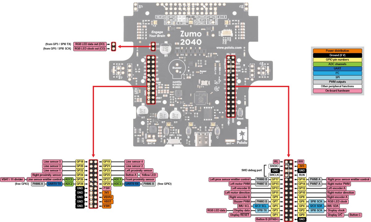 |
Zumo 2040 Main Board top expansion pinout. |
|---|
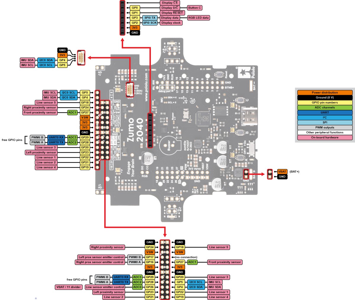 |
Zumo 2040 Main Board front expansion and display connector pinout. |
|---|
I2C0 connector
The I2C0 connector on the main board provides access to the RP2040 microcontroller’s I2C0 bus: GP4 and GP5 for SDA and SCL, respectively, along with 3V3 and GND. This 4-pin JST SH-compatible connector works with our 4-pin JST SH-style cables and uses a pinout that matches that of SparkFun’s Qwiic and Adafruit’s STEMMA QT connection systems, so it should work with most Qwiic and STEMMA QT I²C devices that accept 3.3 V.
 |
6.10. Pin assignments
The table below lists each general-purpose I/O pin on the RP2040 and what it is connected to on the Zumo 2040. This table is helpful if you want to add your own electronics to the Zumo 2040 or write your own low-level code for interfacing with the hardware.
The “RP2040 functions” column lists the most relevant RP2040 peripheral functions. The peripheral functions commonly used by our example code are shown in bold. For a complete list of these functions, see the “GPIO functions” section of the RP2040 datasheet.
The “Zumo 2040 functions” column documents the electronics that the pin is connected to on an unmodified Zumo.
The “Zumo headers” column says which of the expansion headers include the pin. The locations of these headers are shown in Section 6.9.
| Pin | RP2040 functions | Zumo 2040 functions | Zumo headers | ||||
|---|---|---|---|---|---|---|---|
| GP0 | SPI0 RX | UART0 TX | I2C0 SDA | PWM0 A | Button C Display data/command select (D/C) |
Top right, Display | |
| GP1 | SPI0 CSn | UART0 RX | I2C0 SCL | PWM0 B | Display reset (RESET) | Top right, Display | |
| GP2 | SPI0 SCK | UART0 CTS | I2C1 SDA | PWM1 A | Display clock (SCK) | Top right, Display | |
| GP3 | SPI0 TX | UART0 RTS | I2C1 SCL | PWM1 B | Display data (MOSI), RGB LED data |
Top right, Display, RGB: DO (indirect) | |
| GP4 | SPI0 RX | UART1 TX | I2C0 SDA | PWM2 A | Inertial sensors SDA | Top right, Front, I2C0 connector | |
| GP5 | SPI0 CSn | UART1 RX | I2C0 SCL | PWM2 B | Inertial sensors SCL | Top right, Front, I2C0 connector | |
| GP6 | SPI0 SCK | UART1 CTS | I2C1 SDA | PWM3 A | RGB LED clock | Top right, RGB: CO (indirect) | |
| GP7 | SPI0 TX | UART1 RTS | I2C1 SCL | PWM3 B | Buzzer PWM | Top right | |
| GP8 | SPI1 RX | UART1 TX | I2C0 SDA | PWM4 A | Right encoder A | Top right | |
| GP9 | SPI1 CSn | UART1 RX | I2C0 SCL | PWM4 B | Right encoder B | Top right | |
| GP10 | SPI1 SCK | UART1 CTS | I2C1 SDA | PWM5 A | Right motor direction | Top right | |
| GP11 | SPI1 TX | UART1 RTS | I2C1 SCL | PWM5 B | Left motor direction | Top right | |
| GP12 | SPI1 RX | UART0 TX | I2C0 SDA | PWM6 A | Left encoder A | Top right | |
| GP13 | SPI1 CSn | UART0 RX | I2C0 SCL | PWM6 B | Left encoder B | Top right | |
| GP14 | SPI1 SCK | UART0 CTS | I2C1 SDA | PWM7 A | Right motor PWM | Top right | |
| GP15 | SPI1 TX | UART0 RTS | I2C1 SCL | PWM7 B | Left motor PWM | Top right | |
| GP16 | SPI0 RX | UART0 TX | I2C0 SDA | PWM0 A | Right proximity emitter control | Top right, Front | |
| GP17 | SPI0 CSn | UART0 RX | I2C0 SCL | PWM0 B | Left proximity emitter control | Top right, Front | |
| GP18 | SPI0 SCK | UART0 CTS | I2C1 SDA | PWM1 A | Line sensor 5 (DN5, rightmost) | Top left, Front | |
| GP19 | SPI0 TX | UART0 RTS | I2C1 SCL | PWM1 B | Line sensor 4 (DN4) | Top left, Front | |
| GP20 | SPI0 RX | UART1 TX | I2C0 SDA | PWM2 A | Line sensor 3 (DN3) | Top left, Front | |
| GP21 | SPI0 CSn | UART1 RX | I2C0 SCL | PWM2 B | Line sensor 2 (DN2) | Top left, Front | |
| GP22 | SPI0 SCK | UART1 CTS | I2C1 SDA | PWM3 A | Line sensor 1 (DN1, leftmost) | Top left, Front | |
| GP23 | SPI0 TX | UART1 RTS | I2C1 SCL | PWM3 B | Left proximity sensor | Top left, Front | |
| GP24 | SPI1 RX | UART1 TX | I2C0 SDA | PWM4 A | Right proximity sensor | Top left, Front | |
| GP25 | SPI1 CSn | UART1 RX | I2C0 SCL | PWM4 B | Yellow LED / Button A | Top left | |
| GP26 | SPI1 SCK | UART1 CTS | I2C1 SDA | PWM5 A | ADC0 | Battery level input (VBAT/11), Line sensor emitter control (DNE) |
Top left, Front |
| GP27 | SPI1 TX | UART1 RTS | I2C1 SCL | PWM5 B | ADC1 | Front proximity sensor | Top left, Front |
| GP28 | SPI1 RX | UART0 TX | I2C0 SDA | PWM6 A | ADC2 | Top left, Front | |
| GP29 | SPI1 CSn | UART0 RX | I2C0 SCL | PWM6 B | ADC3 | Top left, Front | |
| QSPI_SS_N | Flash chip select, BOOTSEL | Button B | Top right: BTNB+ (indirect) | ||||
| RUN | Active-low reset | Reset button | Top right | ||||
| SWCLK | Serial Wire Debug (SWD): clock | Top right | |||||
| SWDIO | Serial Wire Debug (SWD): data I/O | Top right | |||||
6.11. Adding electronics
This section gives tips for how to expand the Zumo 2040 with additional electronics.
Free I/O pins
The pins GP28 and GP29 are free I/O pins that are not used for anything on the Zumo 2040. Both of these pins can be used as general purpose inputs, analog inputs, digital outputs, or PWM outputs.
The Zumo 2040 has several traces that you can cut to disconnect I/O pins from their on-board functions, freeing them up for other uses. There is a cuttable SMT jumper for GP7 labeled “Buzzer = 7” in the OLED display area and another for GP26 labeled “26 = BAT LEV” on the left edge of the main board. The front sensor array contains cuttable traces for the pins used by the front sensors: GP18 (J21), GP19 (J1), GP20 (J9), GP21 (J2), GP22 (J3), GP23 (J4), GP24 (J22), GP26 (J6), and GP27 (J15). The RP2040 functions available on these pins are documented in Section 6.10.
Adding an I²C device
There are two types of devices that can connect to an I²C bus: a controller is a device that initiates transfers of data, generates clock signals, and terminates transfers, while a target is a device that is addressed by a controller.
You can add I²C devices to the Zumo 2040 by connecting the SDA pin of each device to GP4 and connecting the SCL pin of each device to GP5. Both of those pins are available in several places on the expansion headers and on the I2C0 connector (see Section 6.9). These are the same pins used by the inertial sensors documented in Section 6.7, so the I²C addresses of any targets you add here must be different than the I²C addresses of the inertial sensors. The LIS3MDL uses address 30 (0b0011110) and the LSM6DSO uses address 107 (0b1101011). The GP4 and GP5 pins are each pulled up to 3.3 V with a 10 kΩ resistor.
The RP2040 acts as an I²C controller on the GP4/GP5 bus when it accesses the inertial sensors. If you are adding another I²C controller to the bus, it is probably best to avoid the complexity of a multi-controller setup and instead configure the RP2040 to be an I²C target (or not use the bus at all).
Another option is to add an I²C device by connecting its SDA pin to GP28 and connecting its SCL pin to GP29. These are free I/O pins that are not used for anything on the Zumo 2040. However, note that if you want to use hardware I2C on these pins, you would need to use the RP2040’s I2C0 module, which is the same one used for the inertial sensors on GP4 and GP5. To work around this conflict, you could use a software I²C implementation for one of the busses or consider adding code to change the I2C0 pin function selections dynamically.
Any I²C devices you add must be compatible with the 3.3 V levels used by the RP2040 or use a level shifter.
Adding a UART serial device
The RP2040’s UART0 module is available on the free I/O pins GP28 (TX) and GP29 (RX). Alternatively, if you remove the OLED display, you can use UART0 on GP0 (TX) and GP1 (RX). Any UART serial devices you add must be compatible with the 3.3 V levels used by the RP2040 or use a level shifter. The RP2040’s I/O pins are not 5 V tolerant.
Adding an SPI device
If you remove the OLED display, you can use the RP2040’s SPI0 module on pins GP0 (RX), GP1 (CSn), GP2 (SCK), and GP3 (TX). The RGB LEDs typically use SPI0, but it is possible to work around this conflict by changing the SPI0 pin function selections dynamically, and the libraries we provide for the Zumo 2040 OLED and RGB LEDs show how to do this.
6.12. Schematics and dimensions
The schematic diagram for the Zumo 2040 robot is available as a PDF:
- Zumo 2040 schematic diagram (369k pdf)
Dimensions
Basic dimension diagrams are available as PDFs for the assembled Zumo 2040 robot and its circuit boards:
- Zumo 2040 Robot dimension diagram (1MB pdf)
- Zumo 2040 Main Board dimension diagram (2MB pdf)
- Zumo 2040 Front Sensor Array dimension diagram (664k pdf)
Dimensions on the boards that are not included in the above diagrams can be measured from these DXF drawings:
- Zumo 2040 Main Board drill guide (89k dxf)
- Zumo 2040 Front Sensor Array drill guide (49k dxf)
3D Models of the Zumo 2040 are also available in STEP format:
- Zumo 2040 Robot 3D model (42MB step)
- Note: This model uses simplified models of the control electronics to reduce the file size.
- Zumo 2040 Main Board 3D model (23MB step)
- Zumo 2040 Front Sensor Array 3D model (6MB step)
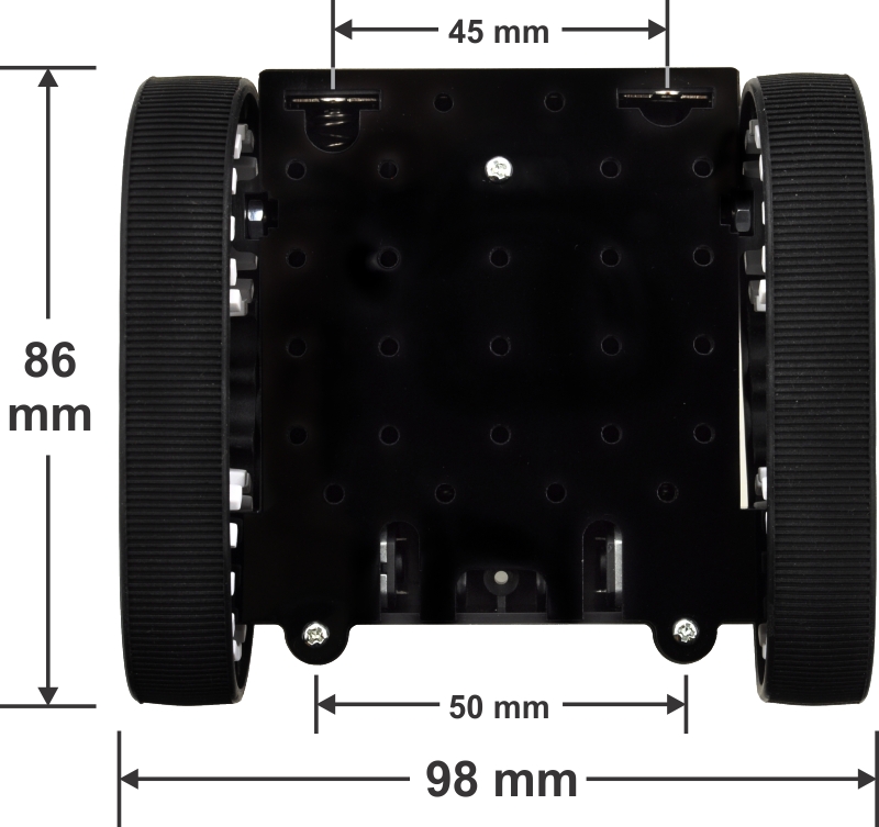
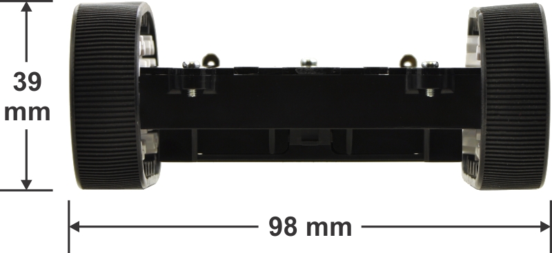
The following pictures show the approximate dimensions of the Zumo chassis used by the Zumo 2040 robot:
|
|
7. Related resources
The Zumo 2040 Robot Libraries and Example Code repository is the main example code resource we provide, with examples in Python and C.
To learn more about programming the RP2040 in Python, see the following resources:
- Raspberry Pi Pico Python SDK (PDF)
- MicroPython documentation
- MicroPython source code
- The Python Lanuage Reference
- The Python Standard Library: MicroPython implements a subset of this
To learn more about programming the RP2040 in C, see the following resources:
- Getting started with Raspberry Pi Pico (PDF)
- Raspberry Pi Pico SDK documentation
- Raspberry Pi Pico SDK source code
- Raspberry Pi Pico SDK examples
These are some general resources about the RP2040:
- Raspberry Pi microcontrollers documentation
- picotool is a tool for interacting with RP2040 devices when they are in BOOTSEL mode
Datasheets for some of the components of the Zumo 2040 are available below:
- RP2040 datasheet
- SH1106 OLED driver datasheet (1MB pdf)
- Texas Instruments DRV8838 motor driver datasheet
- ST LIS3MDL 3-axis magnetometer datasheet (2MB pdf)
- ST LSM6DSO 3D accelerometer and 3D gyroscope datasheet (3MB pdf)
Finally, we would like to hear your comments and questions on the Pololu Robotics Forum!


Home | Forum | Blog | Support | Ordering Information | Lists | Distributors | BIG Order Form | About | Contact
© 2001–2026 Pololu Corporation
Same-day shipping, worldwide

|
US toll free: 1-877-7-POLOLU ~
(702) 262-6648 |
|||||||||||||||
| Catalog | Forum | Blog | Support | Ordering | Distributors | About | Contact | |||||||||
|---|---|---|---|---|---|---|---|---|---|---|---|---|---|---|---|---|