Support » Pololu 3pi+ 32U4 User’s Guide » 5. The 3pi+ 32U4 in detail »
5.2. User interface
|
|
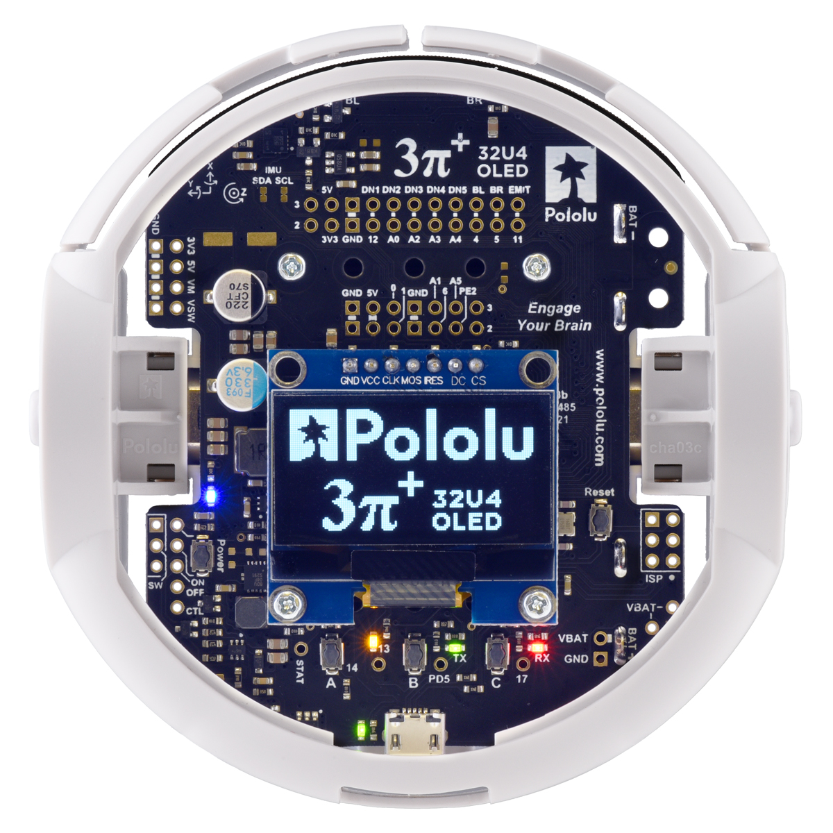
LEDs
The 3pi+ 32U4 control board has seven indicator LEDs, three of which are user-controllable:
- A yellow user LED is connected to Arduino digital pin 13, or PC7. You can drive this pin high in a user program to turn this LED on. The A-Star 32U4 Bootloader fades this LED on and off while it is waiting for a sketch to be loaded.
- A green user LED is connected to Arduino pin 30, or PD5, and lights when the pin is driven low. While the board is running the A-Star 32U4 Bootloader or a program compiled in the Arduino environment, it will flash this LED when it is transmitting data via the USB connection.
- A red user LED is connected to Arduino pin 17, or PB0, and lights when the pin is driven low. While the board is running the A-Star 32U4 Bootloader or a program compiled in the Arduino environment, it will flash this LED when it is receiving data via the USB connection.
These three user LEDs are all located near the bottom of the board, and the Pololu3piPlus32U4 library contains functions that make it easier to control them (see Section 7). Some of the LED control lines are also display interface lines (green and red on the OLED version; all three LEDs on the original LCD version), so you will see them flicker when you update the display. The green and red user LEDs also share I/O lines with pushbuttons (see below).
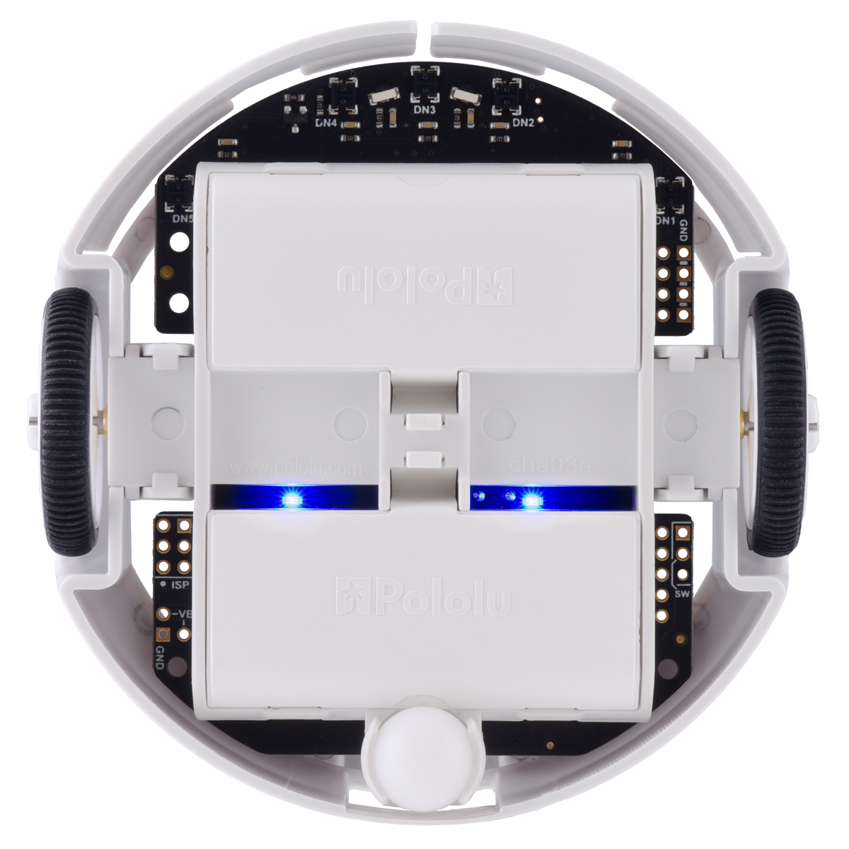
The remaining four LEDs are power indicators:
- A blue power LED next to the power button indicates when the 8 V motor voltage regulator is active. The regulator is powered by the 3pi+’s batteries, so the power switching circuit must be turned on.
- A blue power LED on the left underside of the 3pi+ (closer to the power button) indicates when the 5 V regulator is active. The regulator is powered by the 3pi+’s batteries, so the power switching circuit must be turned on.
- A blue power LED on the right underside of the 3pi+ (farther from the power button) indicates when the 3pi+’s logic circuit, including the microcontroller, is receiving 5V. Logic power can come from either the 5 V regulator or from USB, so this LED will be lit when either the power switching circuit is turned on or when the 3pi+ is plugged in to USB.
- A green power LED next to the USB connector indicates when the USB bus voltage (VBUS) is present.
Pushbuttons
The 3pi+ 32U4 control board has five pushbuttons: a power button on the left, a reset button on the right, and three user pushbuttons located along the rear. The user pushbuttons, labeled A, B, and C, are on Arduino pin 14 (PB3), pin 30 (PD5), and pin 17 (PB0), respectively. Pressing one of these buttons pulls the associated I/O pin to ground through a resistor.
The three buttons’ I/O lines are also used for other purposes: pin 14 is MISO on the hardware SPI interface, pin 30 and pin 17 control the green and red user LEDs, and some pins are display interface lines (pin 30 and pin 17 on the OLED version; all three buttons on the original LCD version). Although these uses require the pins to be driven by the AVR (or SPI slave devices in the case of MISO), resistors in the button circuits ensure that the 3pi+ 32U4 Control Board will not be damaged even if the corresponding buttons are pressed at the same time, nor will SPI or display communications be disrupted. The functions in the Pololu3piPlus32U4 library take care of configuring the pins, reading and debouncing the buttons, and restoring the pins to their original states.
Buzzer
The buzzer included with the 3pi+ 32U4 control board can be soldered into the designated through-holes and used to generate simple sounds and music. By default, it is connected to digital pin 6 (which also serves as OC4D, a hardware PWM output from the AVR’s 10-bit Timer4). If you alternate between driving the buzzer pin high and low at a given frequency, the buzzer will produce sound at that frequency. You can play notes and music with the buzzer using functions in the Pololu3piPlus32U4 library. If you want to use pin 6 for an alternate purpose, you can disconnect the buzzer circuit by cutting the surface-mount jumper next to the buzzer.
Display header
The 3pi+ 32U4 OLED control board has a 1×7 header where you can connect a graphical OLED module with a low-profile male header. The included display has a resolution of 128×64 pixels and uses an SH1106 controller (1MB pdf), which the 3pi+ communicates with via software SPI. On-board level shifters convert 5 V signals from the 3pi+’s microcontroller to the 3.3 V logic level required by the OLED module.
The original 3pi+ 32U4 control board has a 2×7 header where you can connect an 8×2 character LCD with a low-profile male header (or any other LCD with the common HD44780 parallel interface (109k pdf)). You can adjust the LCD contrast with the potentiometer directly above the LCD connector. We recommend using a 2 mm slotted screwdriver to adjust the contrast.
The Pololu3piPlus32U4 library provides functions to show data on a connected display. It is designed to gracefully handle alternate use of the display interface lines by only changing pin states when needed for a display command, after which it will restore them to their previous states. This allows the display interface lines to be used for other functions (such as pushbutton inputs and LED drivers).
Although the OLED and LCD screens have different hardware interfaces, the library presents similar software interfaces for both that generally allow code written for the original (LCD) version of the 3pi+ 32U4 to work on the OLED version with minimal changes. The reverse is also true as long as your code does not make use of the OLED’s graphical capabilities.
Related products


Home | Forum | Blog | Support | Ordering Information | Lists | Distributors | BIG Order Form | About | Contact
© 2001–2026 Pololu Corporation
