View document on multiple pages.
- 1. Contents
- 2. Additional components
- 3. Assembling the Robot Arm Kit for Romi
- 4. Using the Robot Arm for Romi
1. Contents
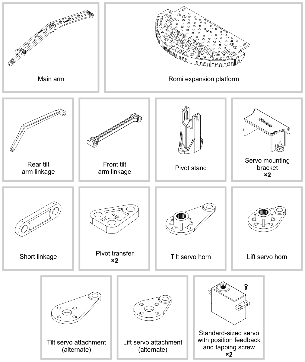
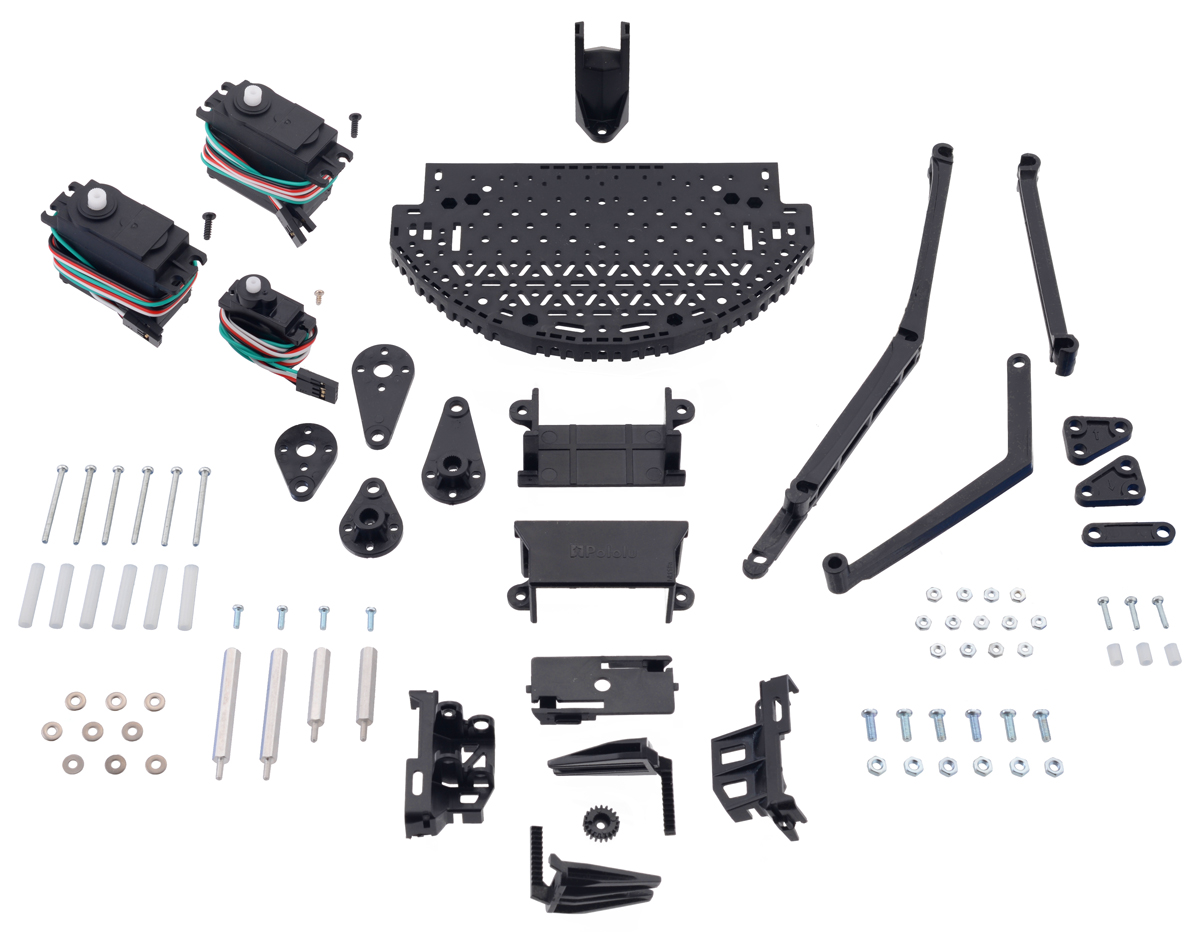
Kit contents
The Robot Arm Kit for Romi consists of the following items:
2. Additional components
The Robot Arm accessory is designed to mount to the top of the Romi chassis. Lifting an object will generally cause the Romi to tilt forward, so we highly recommend using the optional second ball caster attachment, as well as a rubber band to increase the stiffness of the built-in suspension on the front ball caster can help keep the robot stable. If you are using all 6 batteries built into the Romi chassis in series, you can use a step-down voltage regulator such as our 6V, 2.5A Step-Down Voltage Regulator D24V22F6 to safely power the servos. You can find more details about this in Section 4.
You will also need some control electronics, and you might consider some additional components like encoders, sensors, and hardware:
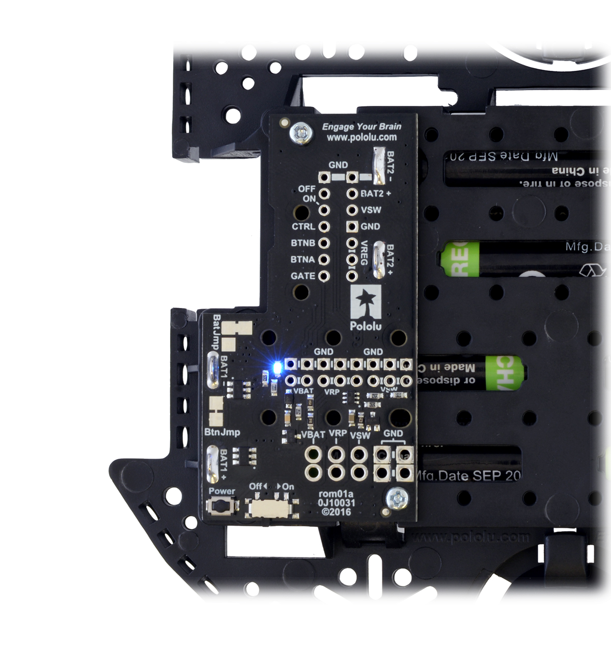
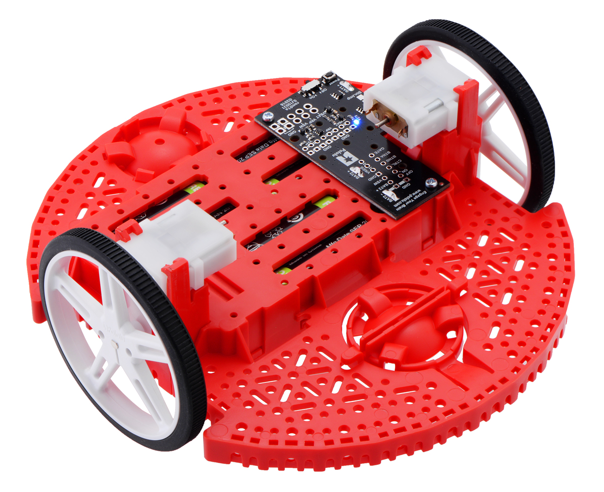
- Power Distribution Board for Romi Chassis – This board helps you get your Romi chassis running quickly. It solders to the chassis’s battery contacts and provides reverse battery protection, several power switching options, and convenient access to the various power busses.
 | Power Distribution Board for Romi Chassis on a black chassis. |
|---|
|
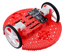 | Power Distribution Board for Romi Chassis. |
|---|
|
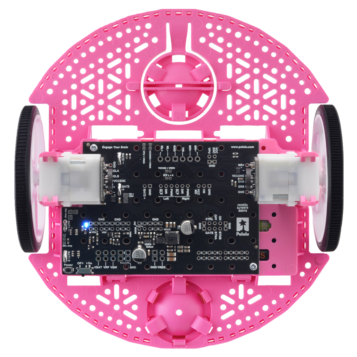
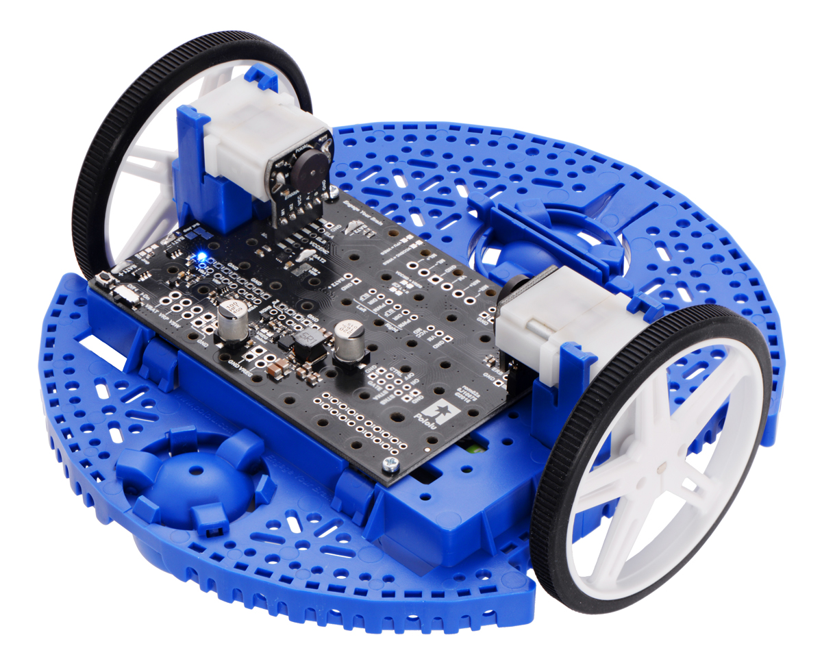
- Motor Driver and Power Distribution Board for Romi Chassis – This board is an alternative to the Power Distribution Board mentioned above. It offers the same features (reverse battery protection, multiple power switching options, and convenient access to various power busses) along with dual motor drivers and a powerful switching step-down voltage regulator that can deliver 2.5 A at 5 V or 3.3 V.
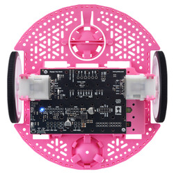 | Motor Driver and Power Distribution Board for Romi Chassis. |
|---|
|
 | Motor Driver and Power Distribution Board for Romi Chassis. |
|---|
|
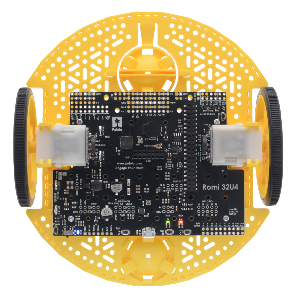
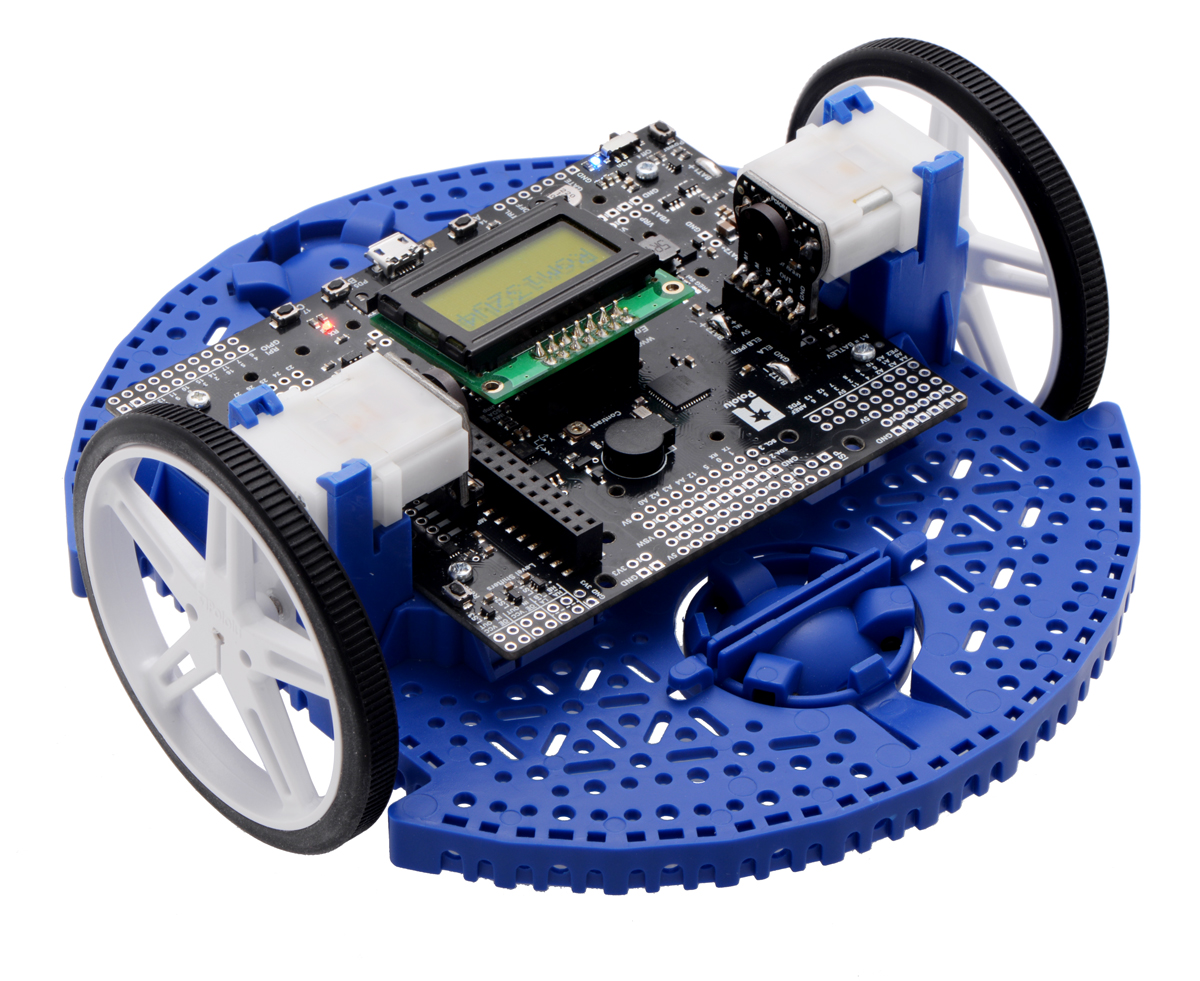
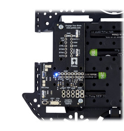
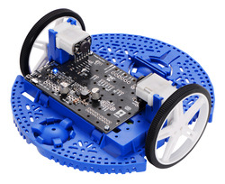
- Romi 32U4 Control Board – This board turns the Romi chassis into a programmable robot based on the Arduino-compatible ATmega32U4 MCU. Its features include integrated dual motor drivers, a versatile power circuit, and inertial sensors, as well as connections for quadrature encoders and an optional LCD. The board also has the ability to interface with an added Raspberry Pi, making the foundation for a complete Raspberry Pi-controlled Romi robot.
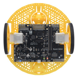 | Romi 32U4 Control Board on a Romi chassis, top view. |
|---|
|
 | Romi 32U4 Control Board with LCD on a Romi chassis. |
|---|
|
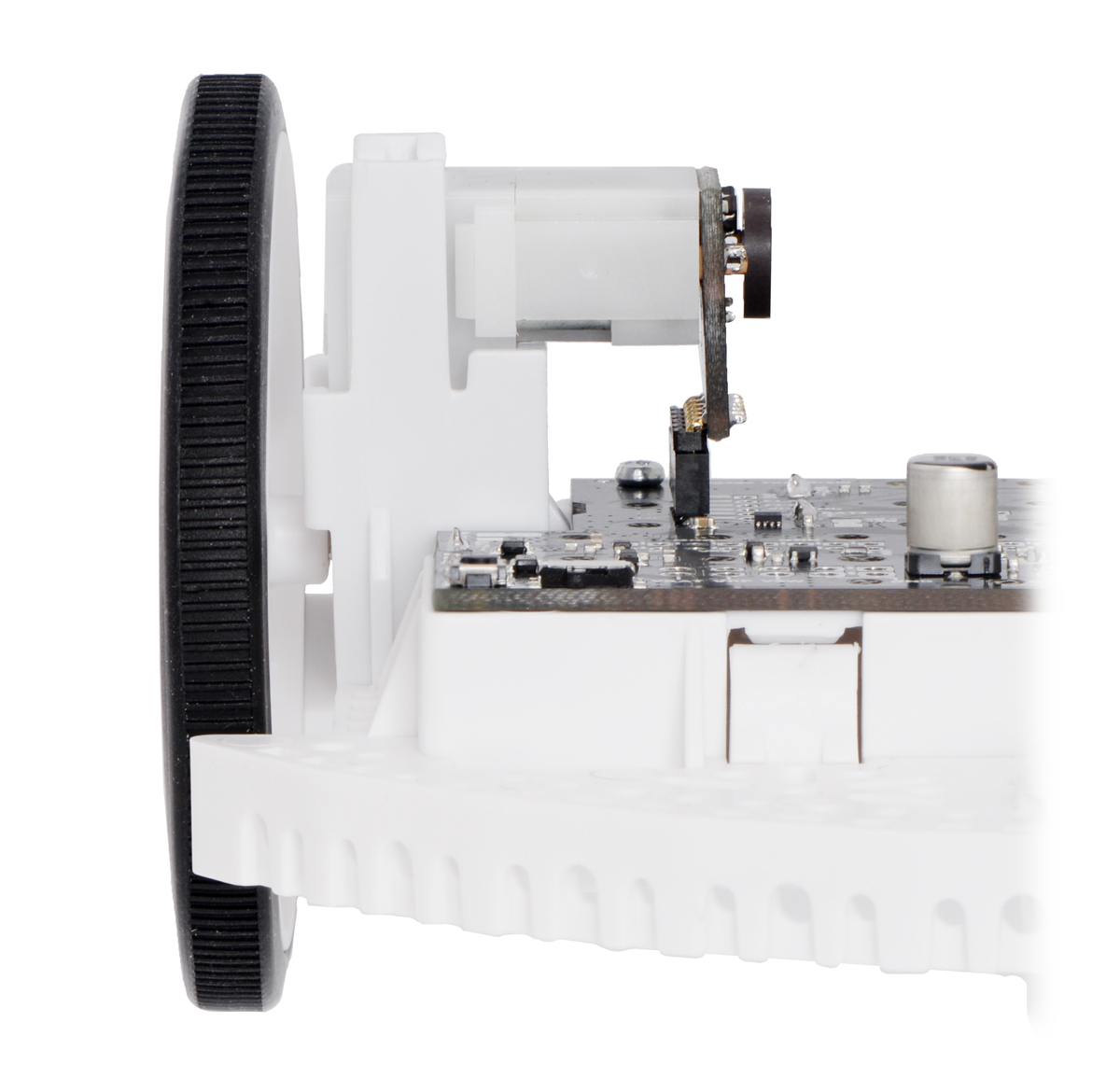
- Romi Encoder Pair Kit – Add quadrature encoders to the mini plastic gearmotors on your Romi chassis with this kit that uses a magnetic disc and Hall effect sensors to provide 12 counts per revolution of the motor shaft. These encoders can plug in directly to the Motor Driver and Power Distribution Board or the Romi 32U4 Control Board.
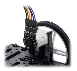 | The included low-profile headers are still long enough to work with our pre-crimped jumper wires. |
|---|
|
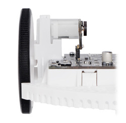 | The Romi Encoder can plug directly into the Motor Driver and Power Distribution Board for Romi Chassis. |
|---|
|
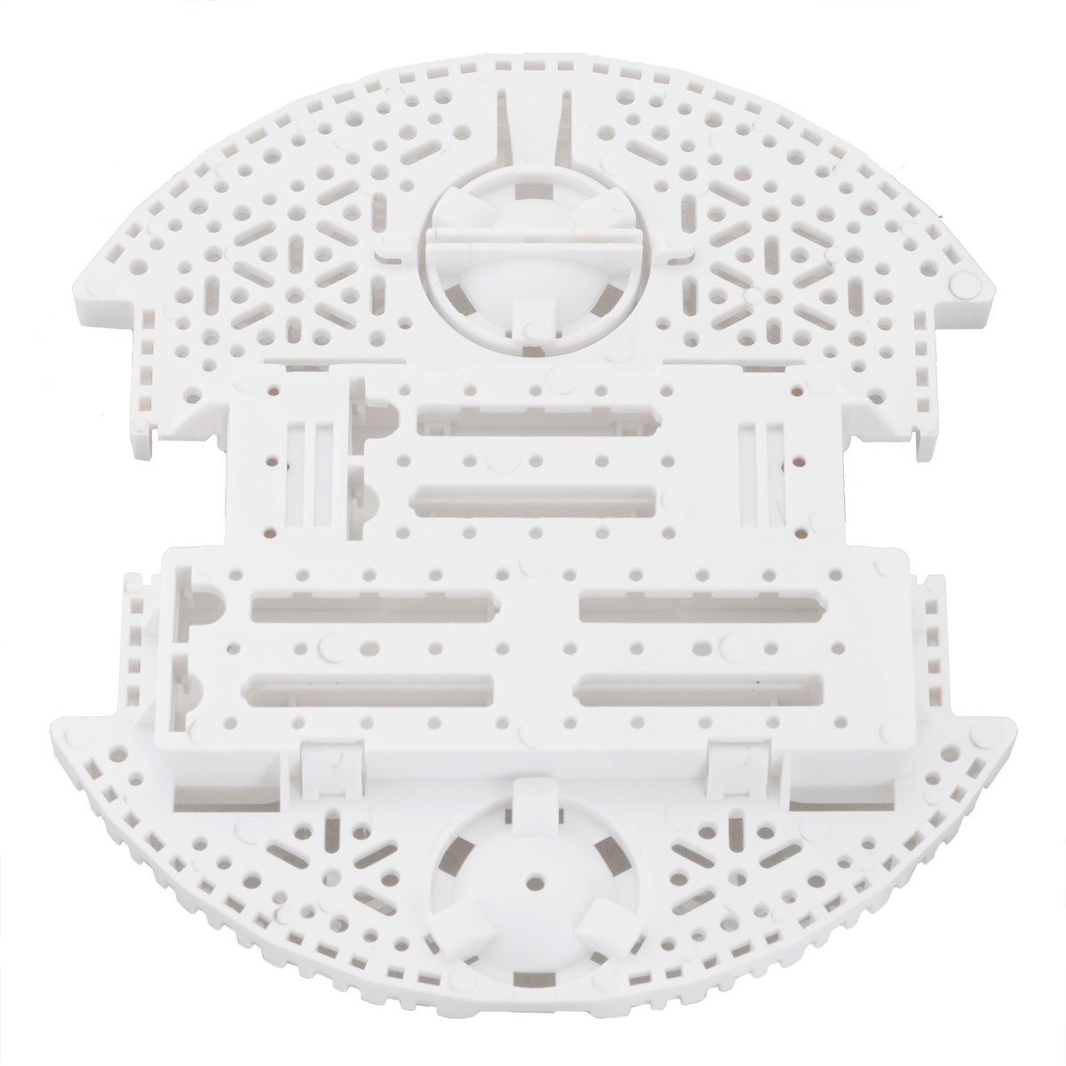
- Romi Chassis components – Chassis components are available individually for use as spare parts or for those who want to put together their own Romi chassis with the color combinations of their choosing.
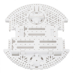 | Romi Chassis Base Plate – White. |
|---|
|
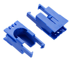 | Romi Chassis Motor Clip Pair – Blue. |
|---|
|
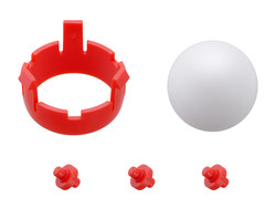 | Romi Chassis Ball Caster Kit – Red. |
|---|
|
 | Pololu Wheel 70×8mm Pair – Yellow. |
|---|
|
3. Assembling the Robot Arm Kit for Romi
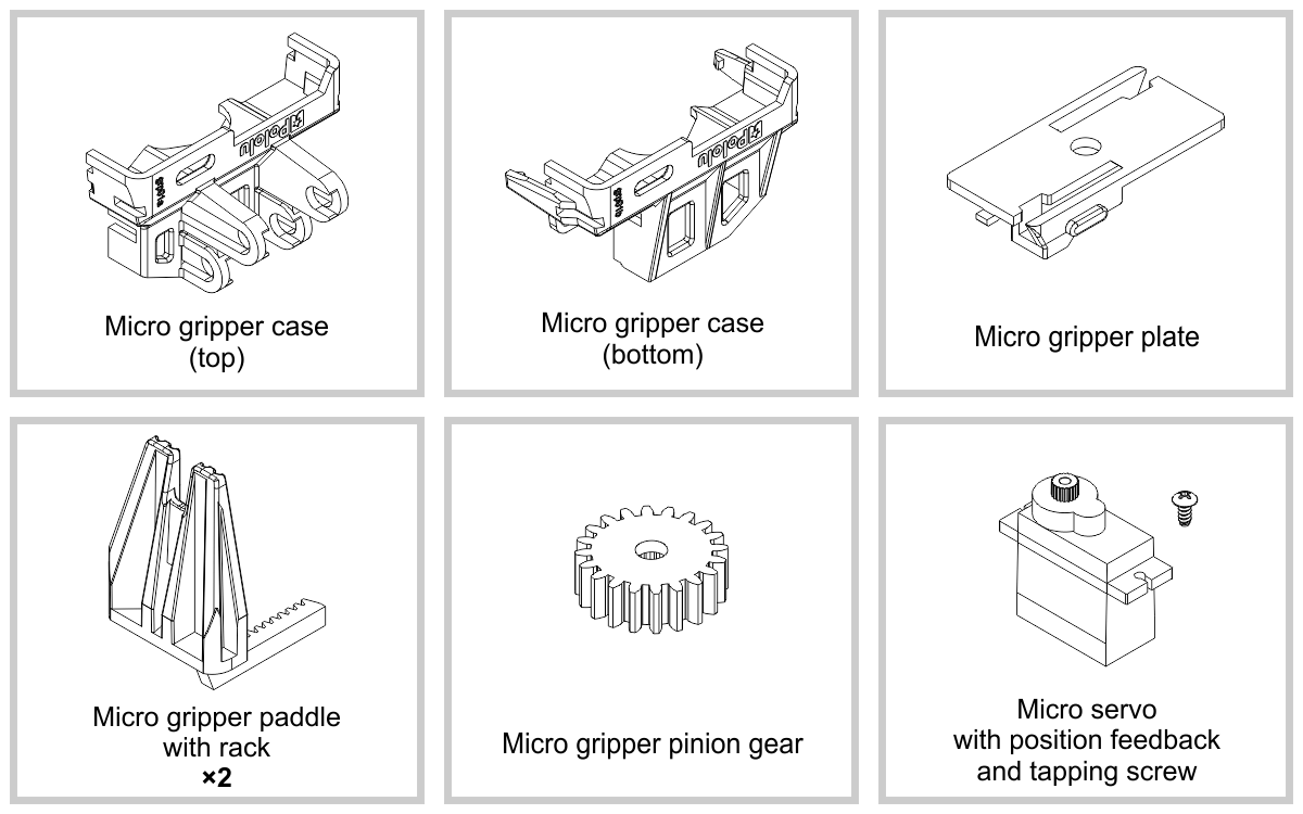
Micro gripper with position feedback servo
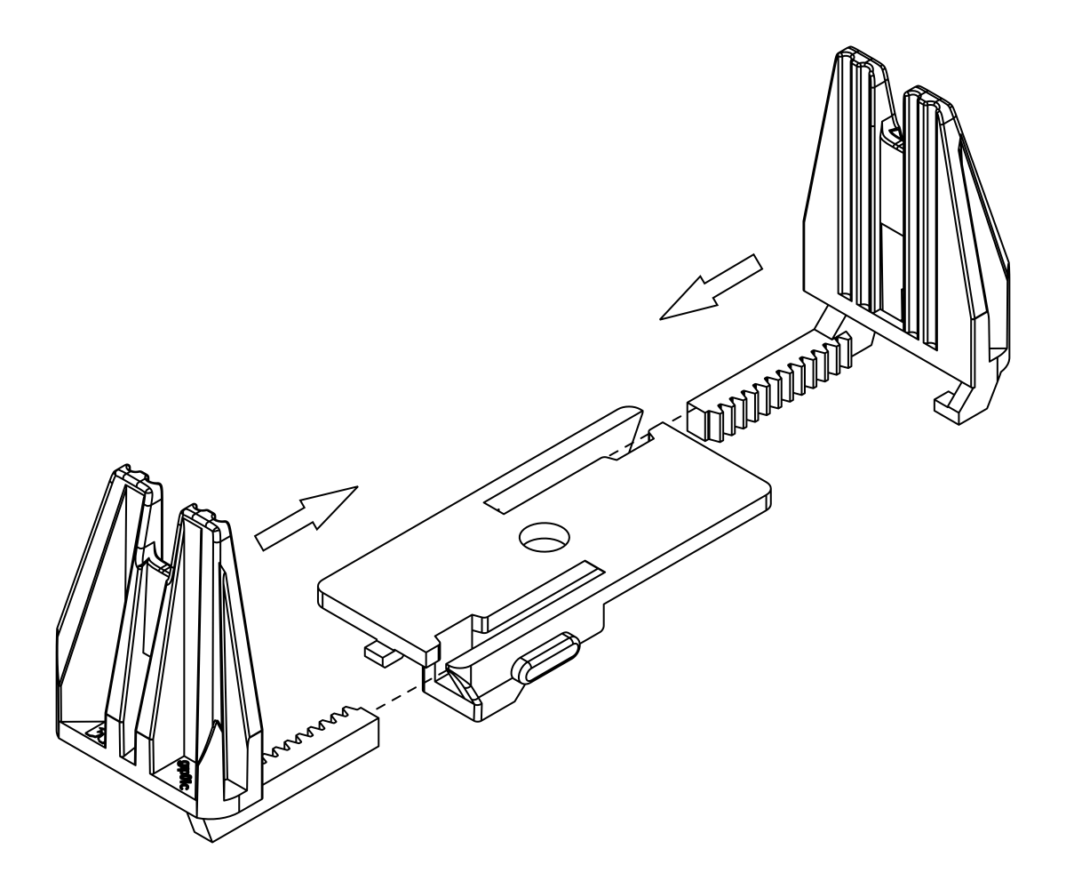
- Slide the two gripper paddles into the slots on the gripper plate and push them together until they meet at the center.
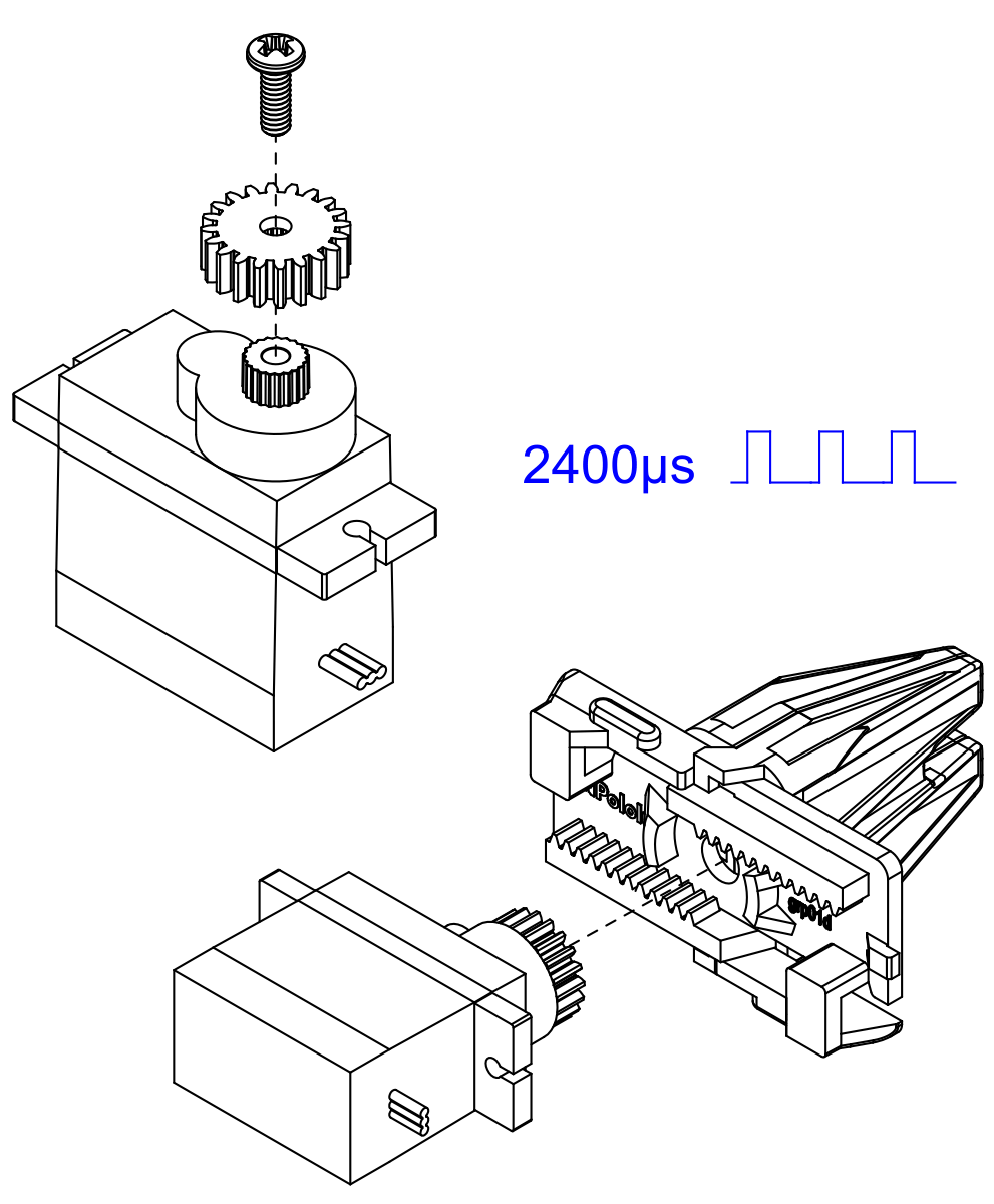
- Install the gripper pinion gear on the micro servo using the included screw and use your servo controller to command the servo to the fully closed position (2400 µs pulse duration). Holding the gripper paddles together, insert the pinion gear between the paddles, making sure the servo is in the orientation as shown.
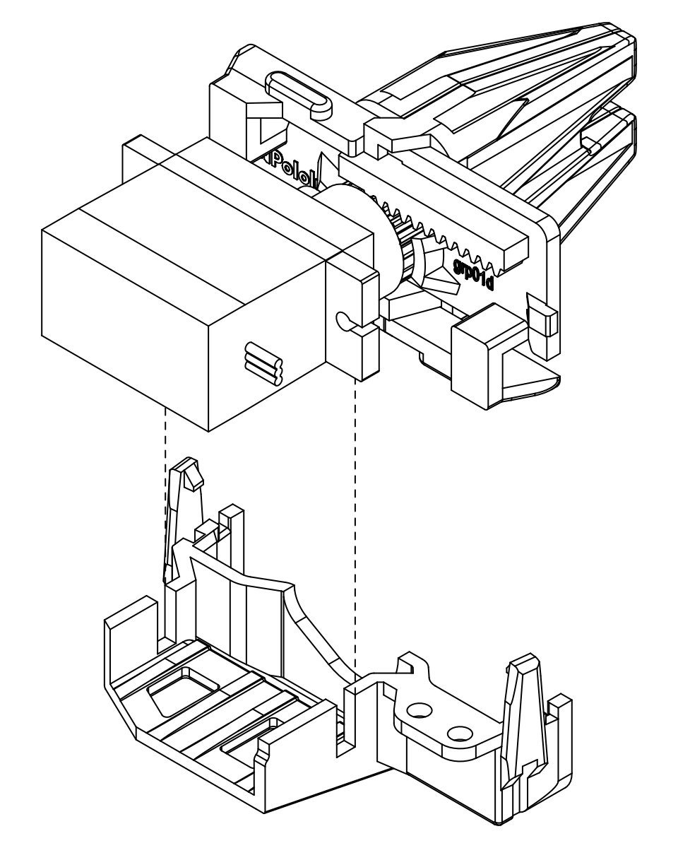
- Keeping the paddles and servo in place, slide the assembly into the bottom micro gripper case.
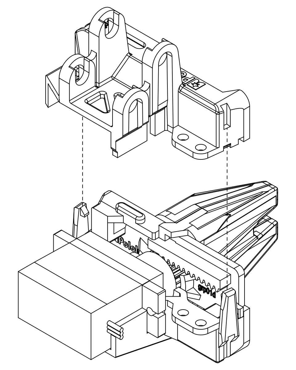
- Align the top micro gripper case with the bottom micro gripper case and press them together, ensuring the clips snap closed.
Your gripper subassembly is now complete! If you ever need to open the micro gripper case. you can gently lift on the clips and pull them apart. A small screwdriver can help get under the clip. Set it aside for now; you will attach it to the end of the arm once it is assembled.
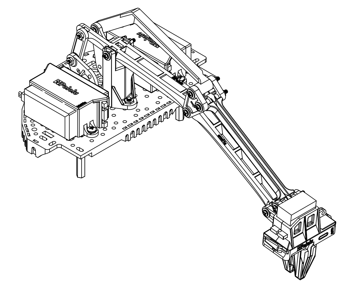
Robot Arm Kit for Romi assembly
Do not overtighten screws. The screws used in the joints of the arm should be firmly tightened, but not enough to deform the nylon spacers. Overtightening the screws can increase the friction in the joints and result in much higher loads on your servos, potentially leading to damage.
- Since the servos will be mounted on top of the mounting holes for the standoffs, install the standoffs on the Romi expansion platform first. Start by putting the #2 nuts in the hexagonal holes shown below, and threading them onto the 1.5″ aluminum standoffs inserted through the mounting hole in the Romi expansion platform.
- Do the same for the 1″ standoffs on the front of the platform. Note that you should be using the two mounting holes closer to the center of the chassis.
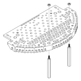 | Installing 1.5″ aluminum standoffs on the Romi expansion platform. |
|---|
|
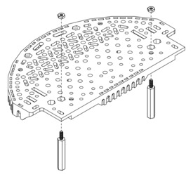 | Installing 1″ aluminum standoffs on the Romi expansion platform. |
|---|
|
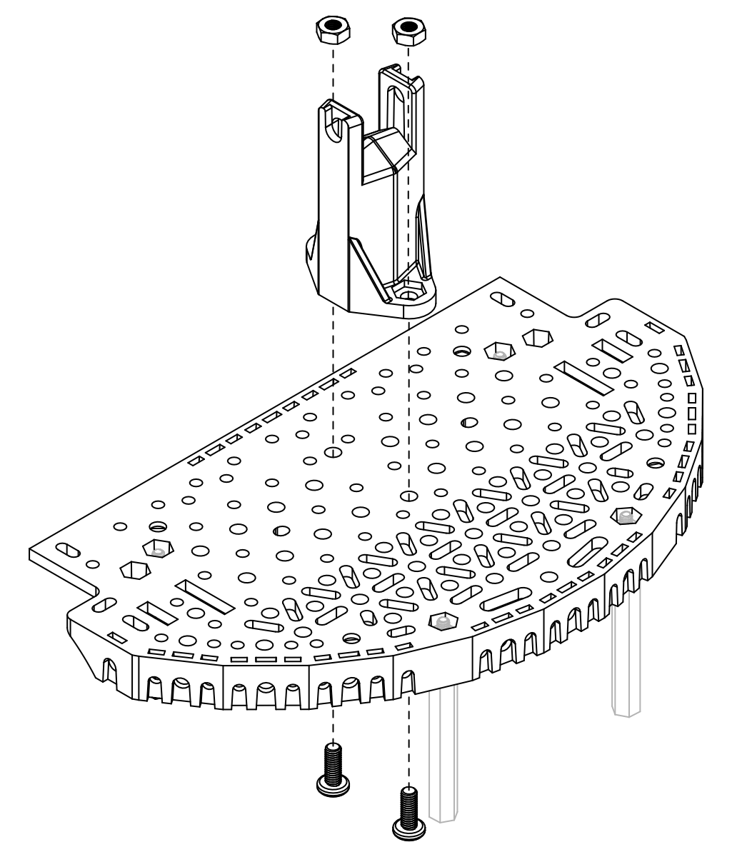
- Next, install the pivot stand onto the Romi expansion platform using two 8 mm M3 screws and M3 nuts. The nuts should be seated into the cut-outs in the base of the stand.
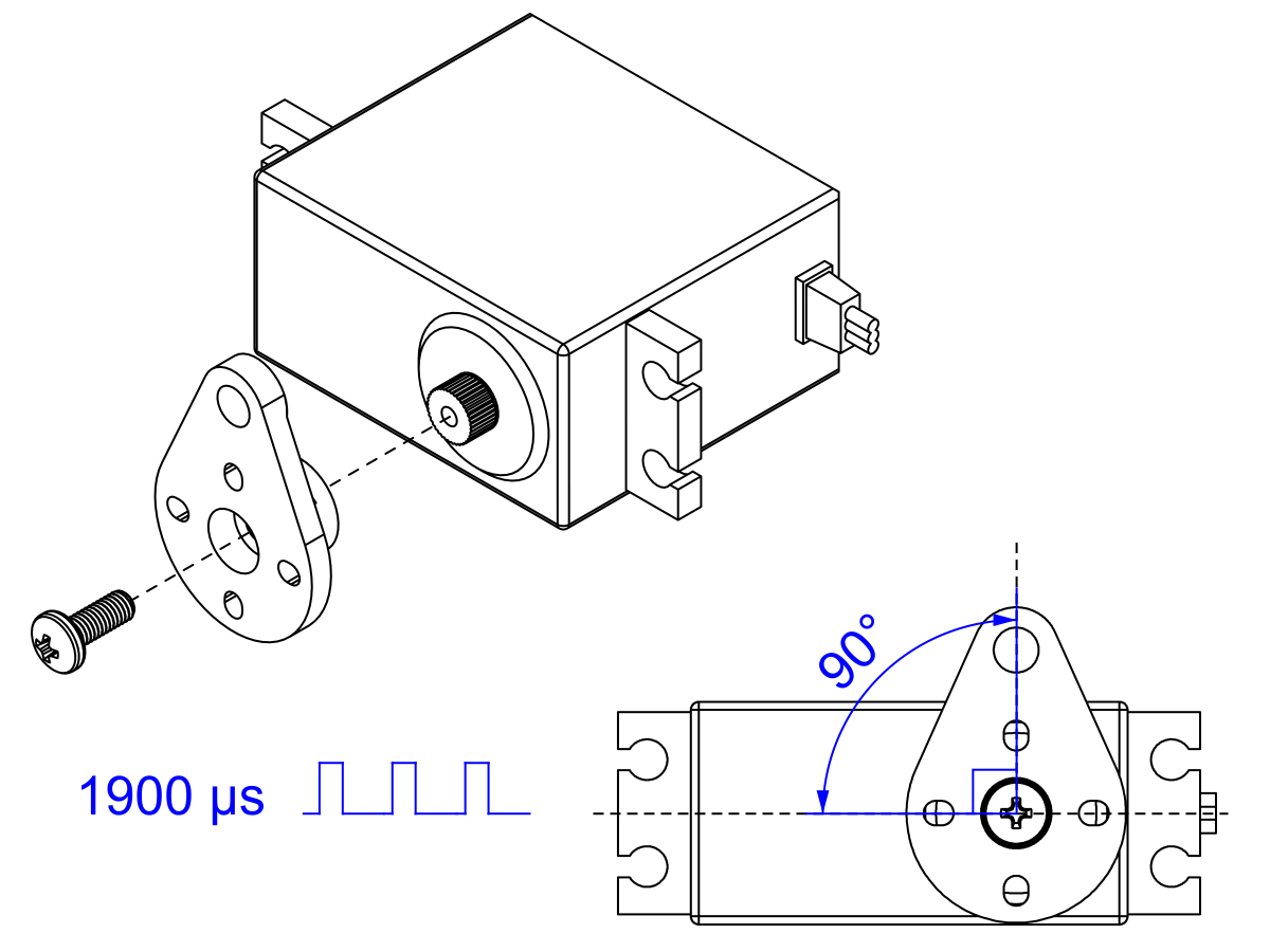
- Prepare the lift servo by using your servo controller to command it to move to the proper starting position (1900 µs pulse duration) and install the lift servo horn (the shorter of the two) with the included mounting screw so it forms a 90° angle to the body of the servo, as shown.
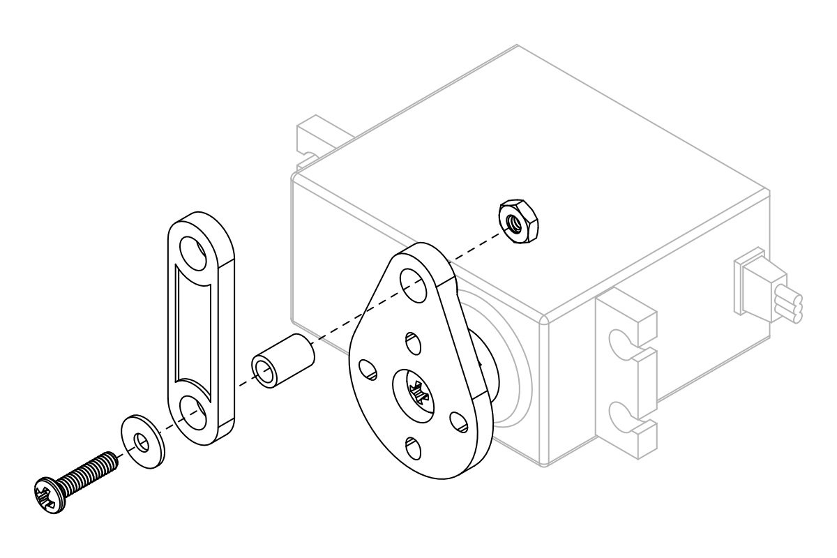
- While the servo is easily accessible, now is a good time to install the short linkage on the lift servo horn. Start by aligning the linkage and inserting a 6 mm nylon spacer through the hole on both parts. Then, insert a 3/8″ #2-56 screw with a washer through the spacer and secure it with a #2 nut on the other side. All of the joints on the arm will use this same method (with appropriately sized screws and nylon spacers).
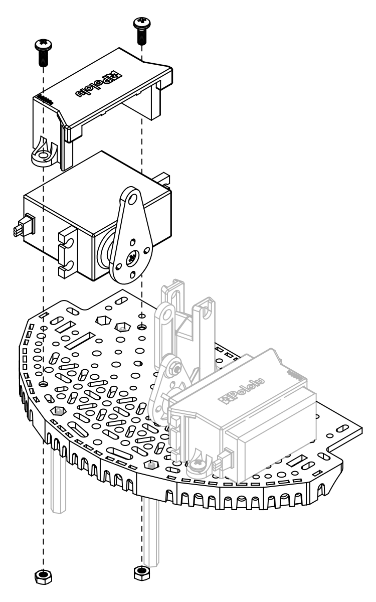
- Use one of the servo mounting brackets to secure the lift servo to the right side of the Romi expansion platform using two 8 mm M3 screws and M3 nuts. The nuts should seat into the cutouts on the underside of the Romi expansion platform.
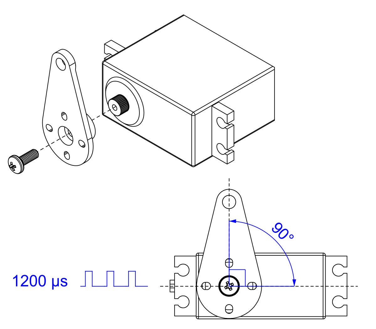
- Prepare the tilt servo by using your servo controller to command it to move to its starting position (1200 µs pulse duration), then install the tilt servo horn with the included mounting screw, making sure it is aligned as shown.
- Use the other servo mounting bracket to secure the tilt servo to the left side of the Romi expansion platform, again using two 8 mm M3 screws and M3 nuts.
- Use a 20 mm nylon spacer, 1″ #2-56 screw, a washer, and a #2 nut to install the main arm to the pivot stand as shown.
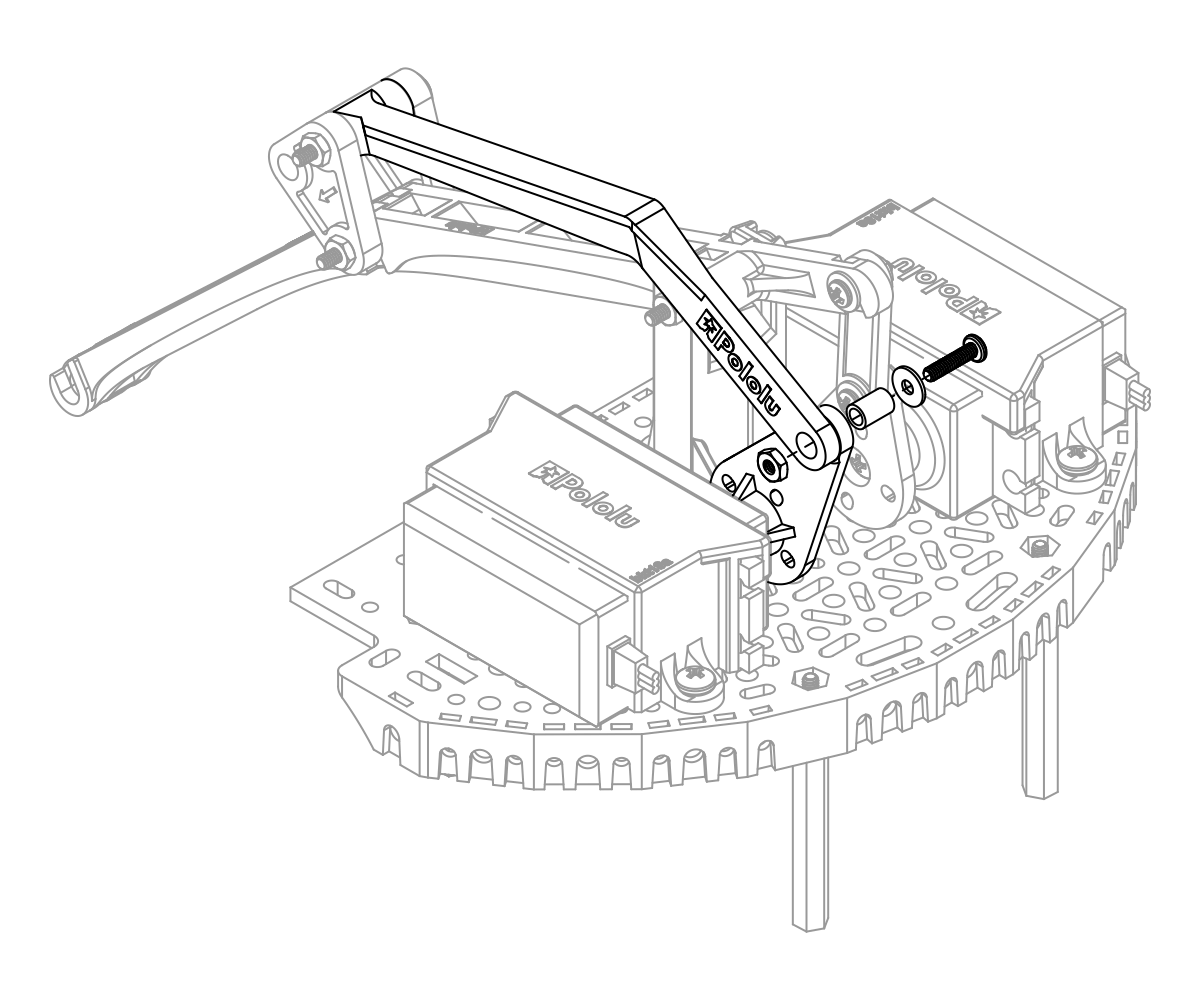
- Connect the main arm to the lift servo linkage using a 6 mm nylon spacer, 3/8″ #2-56 screw, washer, and #2 nut as shown.
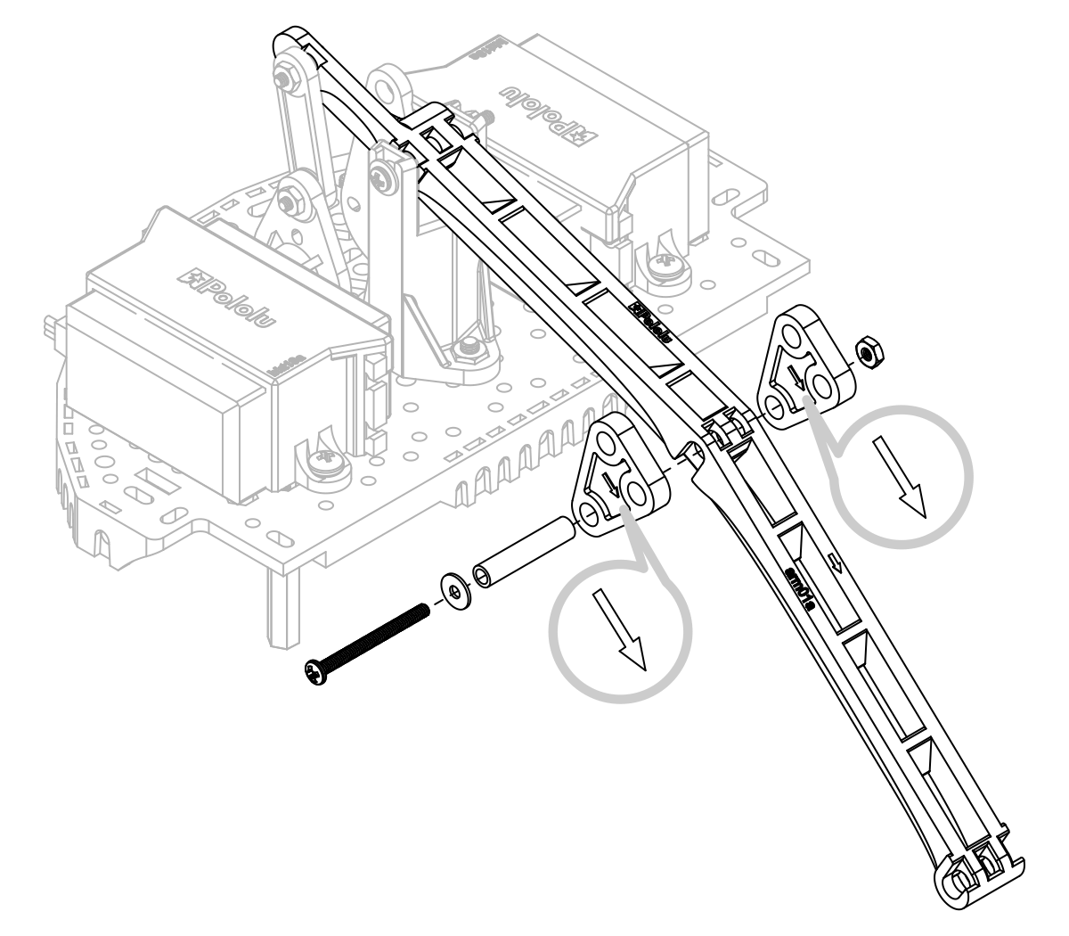
- The next step is to install the two triangular pivot transfer linkages, one on either side of the main arm, making sure the direction indicator arrows are facing forward. Use a 20 mm nylon spacer, 1″ #2-56 screw, a washer, and a #2 nut to secure the 3 components together using the bottom-most hole in the triangular pivot transfer linkages.
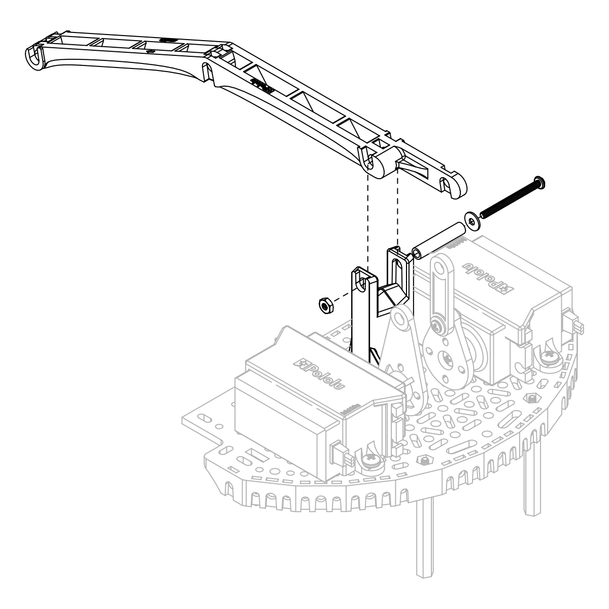
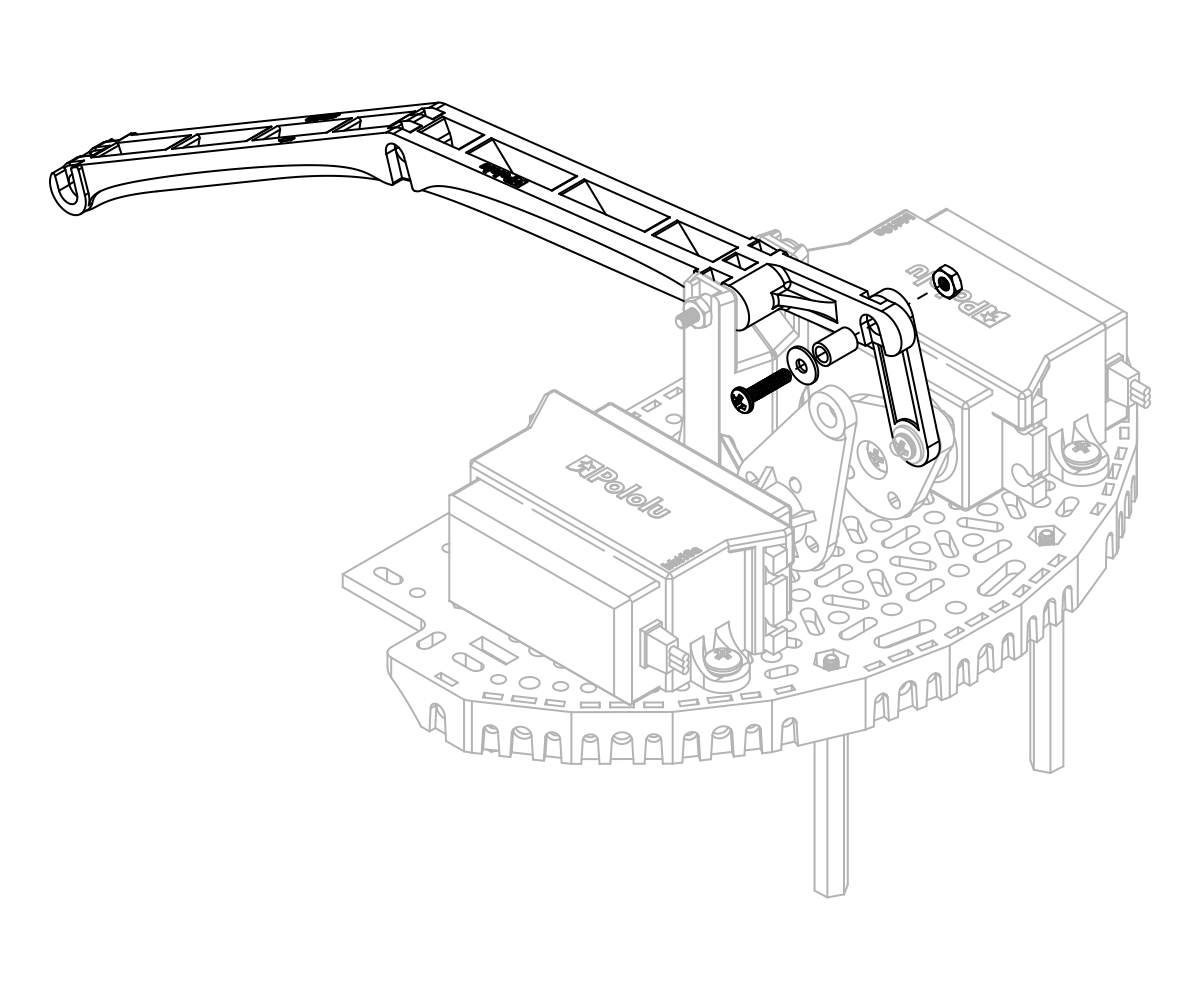
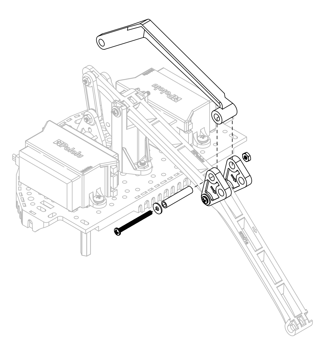
- Connect the rear tilt arm to the top of the triangular pivot transfer linkages (again using a 20 mm nylon spacer, 1″ #2-56 screw, a washer, and a #2 nut). Then, secure the other side of the rear tilt arm to the tilt servo horn using a 6 mm nylon spacer, 3/8″ #2-56 screw, washer, and #2 nut.
 | Installing the rear tilt arm on the Robot Arm for Romi accessory. |
|---|
|
 | Connecting the rear tilt arm to the tilt servo on the Robot Arm for Romi accessory. |
|---|
|
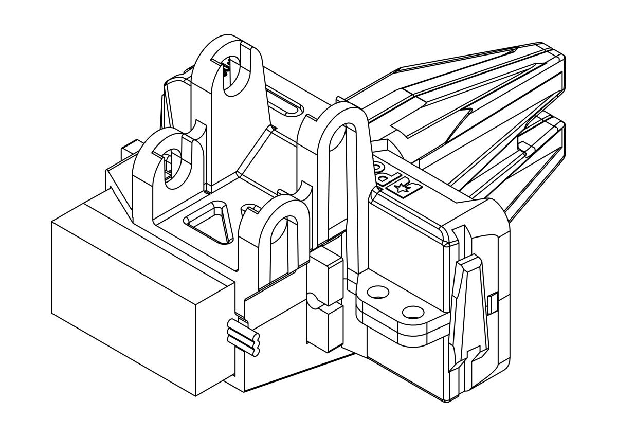
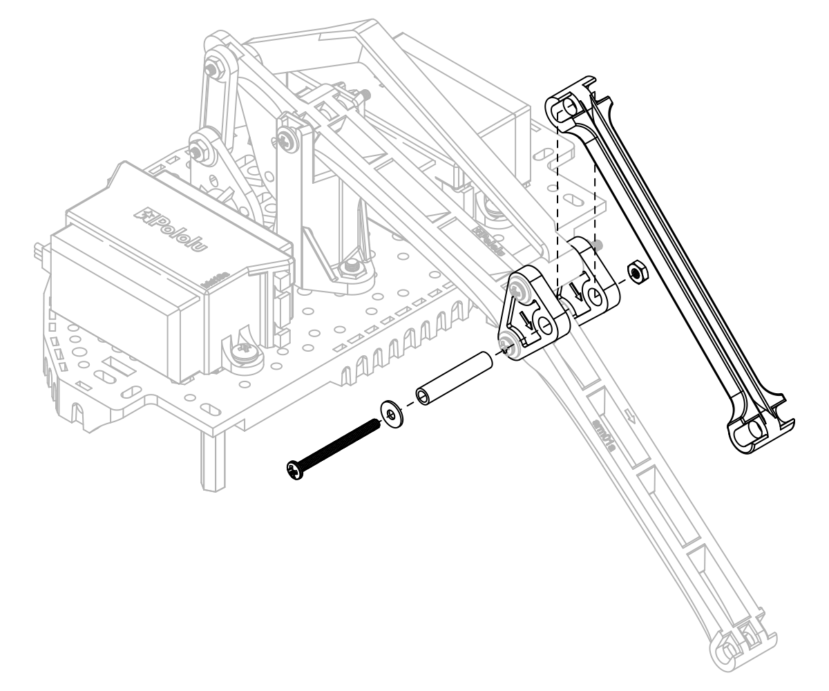
- Using a 20 mm nylon spacer, 1″ #2-56 screw, a washer, and a #2 nut, connect the front tilt arm to the last available mounting holes on the triangular pivot transfer linkages, ensuring the direction indicator arrow on the underside of the front tilt arm is pointing forward.
- Attach the completed gripper sub-assembly to the end of the arm using a 20 mm nylon spacer, 1″ #2-56 screw, a washer, and a #2 nut for each joint. To keep the servo wires tidy, you can snake them back along the main arm through the holes down the spine.
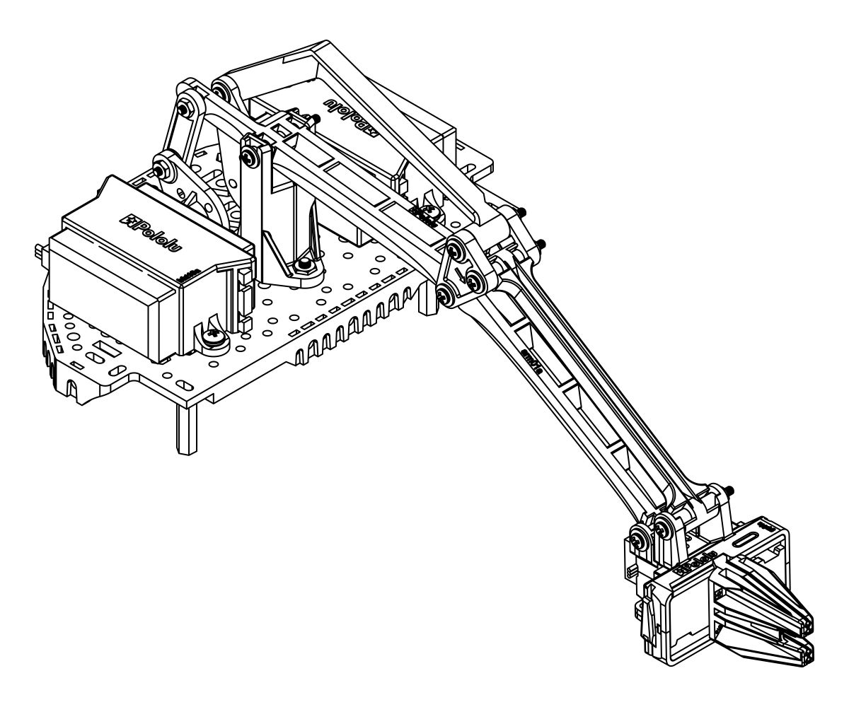
The assembly of your Robot Arm Kit for the Romi is now complete!
The micro gripper can also be flipped around and used in an alternative orientation as shown below.
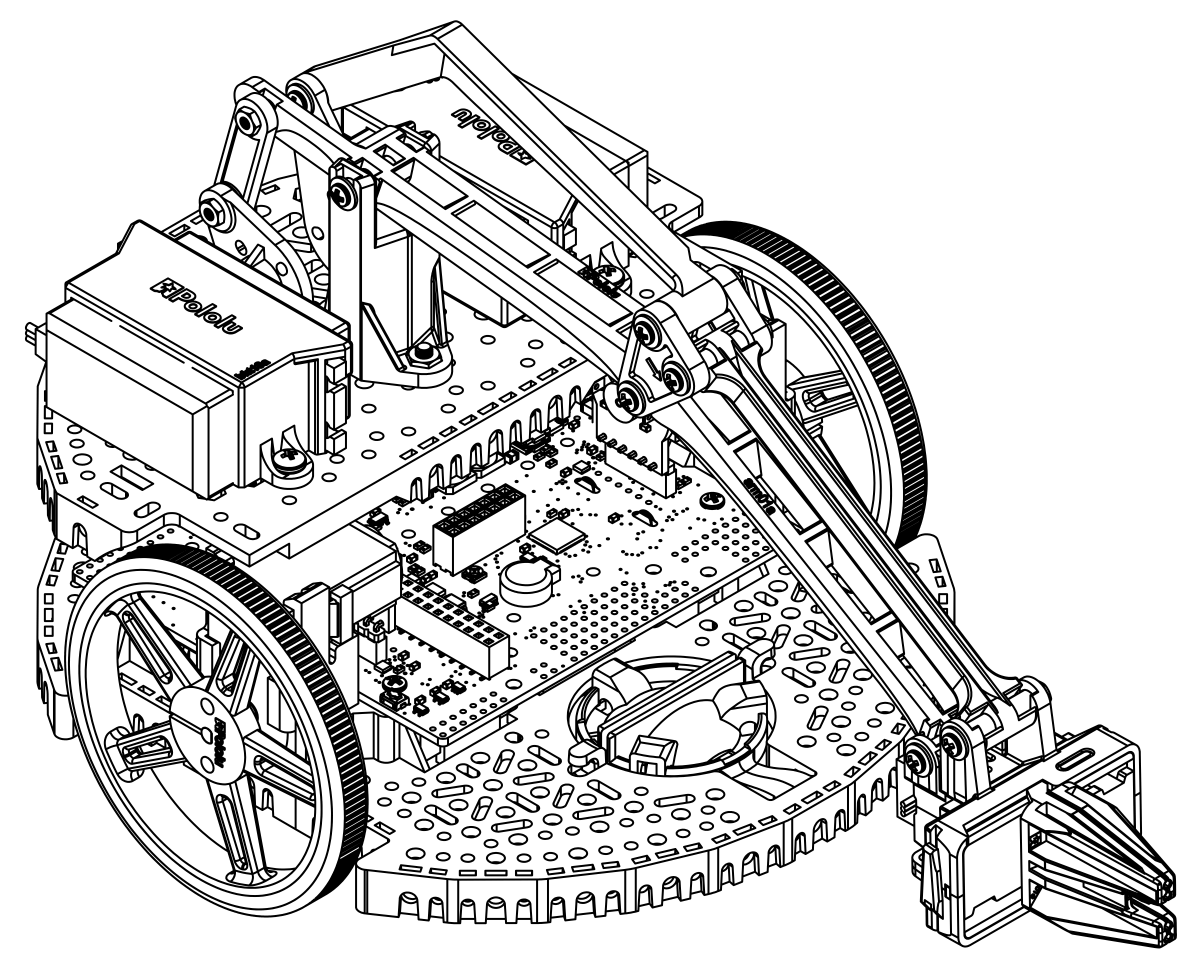
To install the arm accessory on the Romi chassis, align the rear aluminum standoffs with the mounting holes on the rear of the Romi Chassis. and the aluminum standoffs on the front of the arm assembly to the mounting holes nearest to the motors on the Romi chassis, as shown. Insert a 1/4″ #2-56 screw through each mounting hole from the bottom of the chassis, threading it into the standoff above.
The Robot Arm accessory is now installed on the Romi chassis. You can tidy up the wiring for the gripper servo by running the wires along the main arm, passing the wire through the openings along the way, just be sure to leave the servo enough wire to accommodate the gripper’s full range of motion. Additionally, the two rear-most slots on the Romi expansion plate are large enough to pass the servo wires through so they can be routed down to the first level without leaving the profile of the chassis.
Note: Lifting an object will generally cause the Romi to tilt forward, so we highly recommend using the optional second ball caster attachment. The front ball caster is supported by a flexible arm that acts as a suspension system. You can wrap a rubber band around the two hooks located on either side of the ball caster on the top side of the chassis to increase the stiffness of the suspension and help keep the robot stable.
4. Using the Robot Arm for Romi
New to servos?
Hobby servos are small, modular actuators developed by the radio control (RC) hobby industry for remote manipulation of everything from miniature boat rudders and car steering linkages to model airplane flaps and toy parachutist release mechanisms. If you are new to servos, this series of “Engage Your Brain” blog posts has some great information to familiarize you with different types of servos available, how they work, and how to control them.
Overview
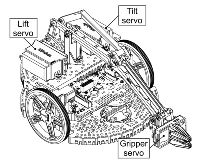
The Robot Arm Kit for the Romi comes with one micro servo for the gripper and two standard-sized servos for moving the arm. All three of these servos are specially modified with an additional wire that gives access to the potentiometer feedback inside the servo. The micro gripper on the end of the arm uses a rack and pinion design with the pinion gear mounted to the servo spline and opposing racks to keep the gripper paddles synchronized and parallel to each other throughout the range of motion. Lifting an object will generally cause the Romi to tilt forward, so we highly recommend using the optional second ball caster in the front of the Romi. Additionally, using a rubber band to increase the stiffness of the built-in suspension on the front ball caster can help stabilize the robot. The recommended maximum payload of the arm is 3.5 oz (100 g).
Powering the servos
All three of the servos have a nominal operating voltage of 4.8 V to 6 V. The larger lift and tilt servos can briefly draw up to around 1.8 A each when commanded to move abruptly, but the typical current draw should be under an amp each. The stall current of the micro gripper servo is approximately 0.8 A at 6 V.
The Romi chassis has multiple power options built into the battery compartment, as discussed in Section 5 of the Romi Chassis User’s Guide. If you are using the 4 battery configuration with the Romi chassis, you can power the servos from the battery voltage. Please note that using all six batteries in series can result in voltages upwards of 9 V with fully-charged NiMH batteries, so you should not power your servos directly from the batteries in this configuration. In this case you can use a step-down voltage regulator such as our 6V, 2.5A Step-Down Voltage Regulator D24V22F6 to safely power the servos.
If you use the Power Distribution Board for Romi Chassis, it defaults to getting power from all six batteries, but it can be reconfigured to be powered from four cells; see the board’s product page for more information.
Range of motion and control signals
 |
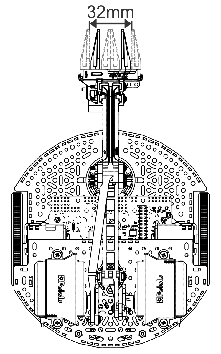
Each of the servos used by the Robot Arm Kit for Romi has a different effective range of motion due to the arm’s geometry. Please note that it is possible to drive the servos in a way that they physically bind the arm and cause them to “fight” each other, which could result in damage to servos or the Robot Arm. Most servos are intended to be used with the 1000 µs to 2000 µs pulse width range commonly used in RC systems; however, many of them can accept a wider range of inputs and will continue responding to them accordingly (moving farther and farther from neutral until they hit their mechanical limits and possibly destroy themselves). The Robot Arm accessory takes advantage of this increased range for the gripper servo. If you followed the assembly instructions correctly, the full range of motion of the gripper servo should correspond to pulse widths from about 500 µs (fully open) to 2400 µs (fully closed). Please note that there could be some unit-to-unit variation in the servos, so if you notice some buzzing when there is no load on the servo, you might try adjusting these values.
 |
Range of motion of the gripper on the Robot Arm for Romi. |
|---|
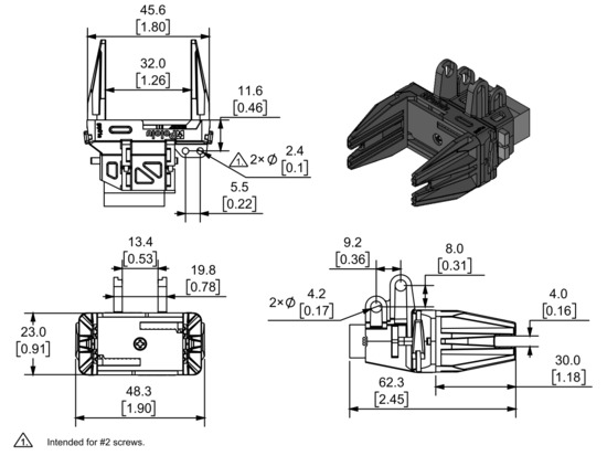 |
Dimension diagram of the Micro Gripper with Position Feedback Servo. Units are mm over [inches]. |
|---|
Similarly, based on the assembly instructions, the full range of the lift servo should be from 1000 µs (fully raised) to 1900 µs (fully lowered), and the full range of the pivot servo should be from 1200 µs (fully down) to 1900 µs (fully up). Again, this might differ slightly due to unit-to-unit variation in the servo.
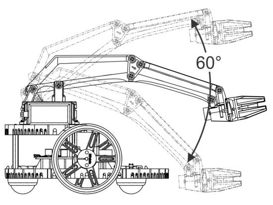 |
Range of motion of the height of the Robot Arm for Romi. |
|---|
 |
Range of motion of the wrist tilt on the Robot Arm for Romi. |
|---|
Feedback
The modified servos that come with the Robot Arm accessory have an extra optional wire that gives direct access to the feedback potentiometer inside the servo. For each servo, there is an approximately 1:1 correspondence between the servo position in milliseconds and the feedback voltage in millivolts, so for example, the feedback voltage will be around 1.5 V at the position corresponding to 1.5 ms servo pulses. You can use this to monitor the position of each servo, which could be useful for detecting if the gripper is holding an object. Also, if you are controlling the servos from a separate source like an RC receiver, you can monitor the feedback with your main controller for feedback about what the arm is doing.