Pololu Blog » Engage Your Brain »
Continuous-rotation servos and multi-turn servos
As I discussed in the introduction to servos, one of the consequences of hobby servos’ intended use is that rotation range is limited to about 180 degrees. In this post, I will talk about two exceptions to this general rule: continuous-rotation servos and multi-turn servos. Each of these products loses some features in return for increased rotational range, so none of them are the ideal actuators many would like them to be. There are some specialty servos developed for robot applications that get around the limitations, but those servos are not as standardized and do not really fit into the hobby servo category, so I am not going into any more detail on those beyond mentioning that they exist.
Before getting to the details of continuous-rotation and multi-turn servos, I should point out that a large part of what makes a hobby servo a standardized product is the servo interface, but that very interface is not capable of supporting servos that can offer precise position control over an arbitrary number of turns. As a quick review, the servo interface consists of a pulse whose duration (pulse width) corresponds to the desired servo output position. To support arbitrarily many rotations of the output shaft, the pulse would have to get arbitrarily long. If we instead wanted the standard pulse range of 0.5-2.5 ms to represent a very large number of rotations, then a very small variation in the pulse width would correspond to a large movement of the output, making that approach unfeasible.
Continuous-rotation servos
Continuous-rotation servos are basically mutilated normal servos that technically do not deserve to be called servos because they lack the feedback control that is the hallmark of any servo system. Let’s begin with a quick review of the basic parts of a servo and how they are logically connected. Physically, the parts look like this:
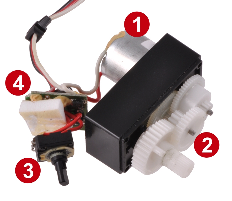 |
Identification of the major components of a disassembled servo. |
|---|
- Motor
- Gearbox
- Position sensor
- Motor control electronics
A block diagram shows how the components are logically connected in a closed-loop system, making a complete servo:
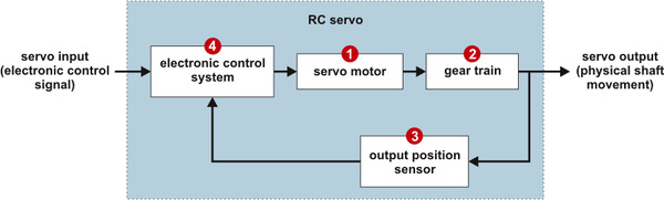 |
A continuous-rotation servo does away with the position sensor (or its connection to the output) and thereby tricks the feedback control circuit into continually driving the motor. For instance, if the feedback value given to the control circuit is fixed to zero degrees, and we tell the servo to go to 45 degrees (remember, we don’t get to actually specify degrees in the interface), it will drive the motor in one direction to try to get there; since the feedback sensor always reports zero degrees, the servo will keep rotating until we tell it to go to zero degrees. If we ask for −45 degrees, the servo will turn the other way, and if we ask for −60 degrees, it will turn faster. There is some limited range of pulse widths where we can effectively control the speed of the motor; once we tell the servo to go to a position that is far enough from where it thinks it is, the motor will always just get full power. So to continue the earlier example, telling the servo to go to −60 degrees might make the shaft spin at full speed, and asking for −70 degrees will not get any more speed.
The appeal of continuous rotation servos is that you can get a motor, gearbox, and motor controller in a relatively neat package and for a relatively low price. Many normal servos can be modified for continuous rotation, so a large range of sizes and powers is available. But, keep in mind that the continuous rotation comes at the expense of position control.
Stock continuous-rotation servos
A few manufacturers have responded to the demand for continuous-rotation servos by offering them as stock items needing no user modifications. These servos often replace the feedback potentiometer with a trimmer potentiometer that can be accessed through a hole in the side of the servo case. The trimpot allows the user to calibrate the servo so that it does not move when it receives a 1.5 ms pulse.
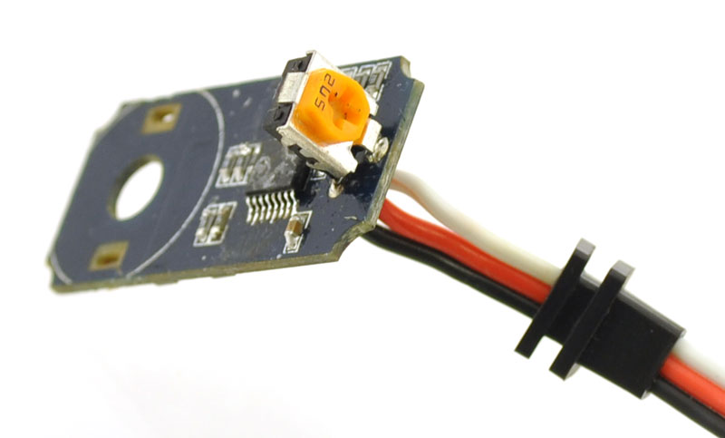 |
Continuous-rotation servo PCB showing trimpot installed instead of feedback potentiometer. |
|---|
These servos manufactured for continuous rotation are convenient since you do not have to make any modifications, but I have only seen them in standard-size versions and without any of the exotic or high-performance options like special gear materials or high-power motors.
Modifying servos for continuous rotation
Most servos are not made for continuous rotation, but many can be modified for continuous rotation. The amount of effort required to modify a servo can vary greatly, so make sure you look into the feasibility of modifying a servo before getting too carried away with your plans for it. There are many step-by-step tutorials online for specific servos, so I recommend checking to see if someone has already modified the particular model you are considering modifying. Generally speaking, you need to be able to do two things:
- Enable the gearbox to mechanically allow for full rotations.
- Disconnect the feedback potentiometer from the output shaft
The first step can be arbitrarily difficult; for instance, this servo would be almost impossible to modify for continuous rotation:
 |
The final gear on this servo does not have teeth all the way around it. |
|---|
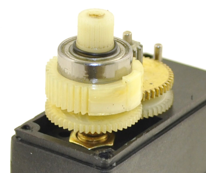
This particular picture is of an S04 servo that is maybe five years old, so it is not necessarily representative of the final gear being used in current units. Fortunately, the final gear not allowing continuous rotation is relatively rare. What is common is some kind of end stop mechanism that prevents the servo from rotating beyond the range supported by the potentiometer, which typically has weak end stops that would be destroyed if a servo went past its limits. This mechanism is most commonly some kind of nub that is molded into a plastic final gear or a dowel pin in a metal gear:
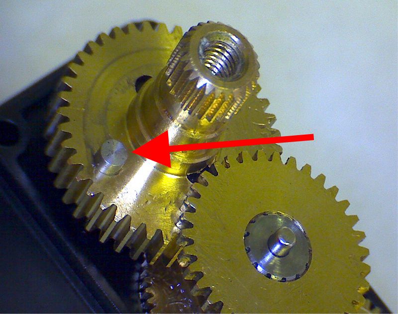 |
Over-rotation prevention pin on a metal-geared servo. |
|---|
The protrusion on the final gear works with corresponding end stops in the servo case. Cutting or grinding the nub off of the output gear is often enough to enable full rotation, but you might need to check the case to make sure nothing interferes with the final gear.
The other basic step in modifying a servo for continuous rotation is decoupling the potentiometer from the final output shaft. This can also be arbitrarily difficult, especially if the potentiometer shaft mechanically supports the output shaft (servos with ball bearings are more likely to mechanically work well without a potentiometer in place). The servo control circuit board still needs to be given a fake position feedback, so you must keep the potentiometer in the circuit, with the shaft in the middle of its range, or replace the potentiometer with a pair of equal resistors.
Full-turn and multi-turn servos
Unlike continuous-rotation servos, multi-turn servos are genuine servos in that they allow closed-loop position control over one or more full revolutions of the output shaft. However, because of the interface limitation I mentioned earlier and because the feedback mechanism is still a potentiometer, you can get at most a few full rotations.
A multi-turn servo is effectively a normal servo with a multi-turn potentiometer, which is a potentiometer that can be turned through multiple revolutions. In practice, a multi-turn servo can use a normal (i.e. one-turn, which is actually more like 270 degrees) potentiometer that is not connected directly to the output but is instead connected by gears such that the servo output turns several rotations for one rotation of the potentiometer. Because the output can turn through several rotations, the servo cannot have the mechanical end stops that regular servos have, so some kind of clutch is required to prevent destruction of the potentiometer if the servo goes out of range. This means that if a multi-turn servo goes past its limit, its absolute position can get reset since the output shaft gets rotated without corresponding rotation of the potentiometer (which is at its limit).
The main tradeoff with multi-turn servos is that you get more rotational range for less angular resolution and accuracy. That means that if you have a system, including your servo pulse generation scheme, that gives you better than half-degree resolution on a normal servo (say you have 256 positions covering 90 degrees), you will get almost two degrees between positions on a full-turn servo (since those 256 positions are now spread over the full 360 degrees).
Like stock continuous rotation servos, multi-turn servos are relatively rare. They are apparently targeted toward model sailboats, so they are often called sail winch servos. Pololu carries the GWS S125, but GWS makes it relatively difficult to keep in stock. I found only a few other models at major hobby stores, and they tend to have much higher prices than normal servos. So, while a multi-turn servo can be perfect if the size and performance happens to match your project, you are probably out of luck if you need a micro multi-turn servo or a high-speed multi-turn servo.
-
Pololu Micro Serial Servo Controller Netduino driver
- 12 July 2011This Netduino driver by customer Stefan Thoolen supports both the MiniSSC2 and the Pololu protocol for controlling a Pololu Micro Serial Servo...
-

Simple 3pi Projects for the Arduino IDE
- 8 August 2011These projects by Daniel J. Sullivan are intended to introduce novice users to all the components on the 3pi robot and how they can be used while...
24 comments

I want to specify the range for the position of the servo, in other words that the servo move between 0 and 360 degrees. But
instead the motor is moving forward and continuous. How can I configure the program to servos?
Thank you

The servo is not made for continuous rotation, and it rotating continuously is a sign that you are asking it to go beyond its limit, which could cause it to be destroyed. The standard 1-2 ms range should get you close to the full turn, and you can gradually expand the range while keeping it centered at 1.5 ms to get to exactly one rotation of range.
By the way, you should direct questions like these to our forums or to more direct tech support.
- Jan

- Jan


Are there any special consideration in modifying a digital servo to be continuous. I have just purchased three HD-9150MG servos and will likely modify one.
Thanks for any advice you can provide.
Cheers, David

We don't know of any specific considerations with digital servos, but I think it's going to depend on the particular model of servo, and we haven't tried modifying that one. You should get a pretty good idea of whether it will be practical as soon as you open it up.
- Kevin (engineer at Pololu)

I recently built a servo motor controller using PIC(microchip 18F), I am just wondering if I have damaged my servos because during a slow increment of angles (debugging purposes) the servo motor will suddenly rotate to the opposite sides at a large angle or perhaps it is just my coding problem for the PIC. Thanks!
Regards,
Chris Tan
What does your question have to do with continuous-rotation or multi-turn servos (the topic of this post)? Also, it would be nice if you didn't call your servos "servo motors" given that one of the posts in the series details why not to call them servo motors.
Anyway, it's completely possible for you to destroy your servos by giving them a bad signal. You should look at your servo control signal with an oscilloscope to see what your program is doing.
- Jan

Thanks for your reply. I would go to my Uni lab to try the oscilloscope and try to pin point whether did the PIC generate the PWM wrongly. I am sorry to post my comments here. I was reading through your blog too hastily. I am sorry but the info here is great and thanks for that! I will try to re-read it slowly. =)
Sincerely,
Chris

1) You cannot get the servo to do anything without using the signal wire. You might get the behavior you want from a regular gearmotor (motor with gearbox, without the servo electronics).
2) Making a servo hit its mechanical limits is quite likely to damage the servo.
- Jan

These hobby servos I'm talking about here are in the ballpark of 100 ounce inches of torque, so your 800 foot pounds is like a thousand times past the scope of this discussion. Even if you were talking about less torque, this would still probably not be the place to discuss your project; you might try our forum instead. If you do, make sure you set up your problem better because a post like the one you made here makes it seem like you have no idea what you want or are putting very little effort into communicating what you want.
- Jan

I am considering a reaction wheel inverted pendulum and I want to attach the rotating disk to a continuous servo motor. Do you think it is effective as a DC motor encoder model. I am interesting in measuring the disk speed and position.
Thanks.
Charbel
I do not quite understand what you are asking, but I suspect continuous rotation servos, which are not particularly high performance motors, are unlikely to be appropriate for inverted pendulum applications or for retrofitting with encoders.
- Jan

Why can't we have servos that have an encoder disk instead of the poti and logic in the controller board to count the turns? They shold also be programmable so that I can tell them what range I want to operate.
I addressed the reasons for some of these hobby servo limitations in the first post of this series, Introduction to servos (see the "Ramifications of the servo’s intended use" section):
https://www.pololu.com/blog/12/introduction-to-servos
The short answer is that the applications these hobby servos are designed for do not need the features you are looking for, and adding them would make them much more expensive. The main feature most of us want from a servo is to hold absolute position, and incremental encoders are not enough if you don't have the option to go to some home position as part of a power-up sequence. High-resolution, absolute position encoders are expensive, and even then, how would the servo know if it is at, say, 10 degrees or 370 degrees when it turns on?
There are some fancier servos for robots that might work for your application. For instance, the Dynamixel servos specify a 300 degree position feedback range and also have a continuous rotation mode. I have not played with one and don't know how easy it is to transition between modes and how it behaves when you do, but maybe that could work for you if you never need to do position control within that 60-degree blind region. I suspect there are some robot hobby servos that have continuous positioning over the full 360 degrees, but I do not specifically know of one.
You might also get a decent servo that will get you at least 150 degrees or so and then use an external 1:3 gearbox to get triple the range (and 1/3 the torque and resolution). Servo City has some external gearboxes for servos, though they might mostly be intended for increasing torque, not reducing it and increasing range.
- Jan

Can this servo go forward and backward in the same project? I want to make a stack bot just to have fun and I copied many codes but my servo is traveling in only one position and not forward and backward. Can this servo support this feature or I should buy a new one?

John.
Either of those routes will probably work, and it doesn't sound very expensive to try. 5k-50k is probably ok for the pot resistance. Let us know how it turns out!
- Jan

Is there such a thing as a hybrid servo that just responds continuously to incremental steps of ≤180° and doesn't track it's absolute rotation? I have an application for a gimbal where I can close the loop outside the servo and doesn't require absolute accuracy or precision over multiple revolutions? Each 360° sweep could be 2 to 20 or more increments.
Today I achieve multiple 360 "sweeps" with a 2:1 gear and 180° servo, but have to return to "null" between each sweep. This results in the "lash" problem of sweeping forward and back which has to be corrected in software, and also slows down the whole process. Better would be no external gears and continuous rotation rather than sweeping forward and back. This could be done in simple increments from the previous position which I can track to correct the accuracy across infinite rotations - if the continuous rotation of the potentiometer and logic of the servo weren't a problem.
The alternative is clearly DC motors with or without encoders, but the simplicity of a single-component hybrid servo solution is attractive.
Thoughts?
- Gordon
I have not heard of such a servo. I don't know if you need the actual feedback and the higher torque you get from typical hobby servos, but perhaps you should look at stepper motors, too (along with our Tic stepper motor controllers: https://www.pololu.com/tic ).
Please share if you do find anything.
- Jan
Post a comment


Home | Forum | Blog | Support | Ordering Information | Lists | Distributors | BIG Order Form | About | Contact
© 2001–2026 Pololu Corporation

