Pololu Blog » Engage Your Brain »
Introduction to servos
 |
Hobby servos are small, modular actuators developed by the radio control (RC) hobby industry for remote manipulation of everything from miniature boat rudders and car steering linkages to model airplane flaps and toy parachutist release mechanisms. The RC market is large and competitive, which has led to a proliferation of servos that have been optimized for characteristics including size, speed, torque, and price. This modularity, variety, ubiquity and cost-effectiveness of servos make them attractive generic actuators for small robots and other electromechanical systems. With hobby and educational robotics gaining popularity, some manufacturers have introduced servos aimed specifically at this newer market. In this first article in a multi-part series about hobby servos and their use in robots, we begin with a high-level overview of hobby servos, including typical applications, common specifications, and some of the ramifications of the intended applications for those using servos in robotics; how servos work, how to use them with your own electronics, and more advanced topics will be addressed in future installations of this series.
Typical servo application
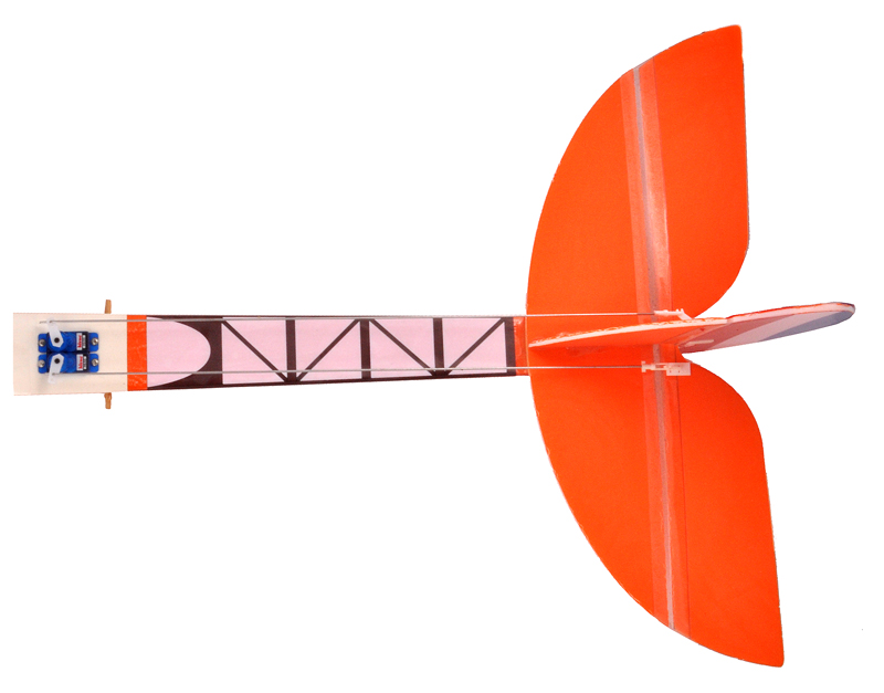 |
Two servos connected to rudder and elevator of a small RC plane. |
|---|
Servos are typically used as part of a modular, radio-based, remote control system that provides one-way communication from an operator to the remote system, which might be a model helicopter or car. The basic goal is for the operator’s manipulation of input controls on a radio transmitter to cause corresponding movements in the servos. Feedback about the success of the radio communication is generally limited to the operator’s direct observation of the model, so these hobby radio control systems are typically used in open spaces and at distances limited by human sight. Miniature cameras with wireless transmitters are available, but these are independent of the basic radio control system and are typically used more for the novelty of the remote point of view than for communication about the remote system’s status. There are four basics elements to a standard radio control system:
- Transmitter
- Receiver
- Receiver battery
- Servos
The transmitter is on one end of a wireless link, and the receiver, its battery, and the servos are connected to each other in the device being controlled to make up the remote end of the wireless connection. (In cheap radio control toys, the three components on the remote end might not be modular and distinct, so there might not be a part to point to and call “the servo” or “the receiver”.) Although the non-servo components might be of limited interest to those not looking for a remote control solution, knowing a bit about the parts normally used with servos can provide some perspective about what to expect from servos, so we will cover the first three components in a bit more detail before moving on to servos.
1. Transmitter
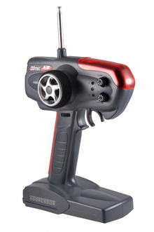 |
Two-channel pistol grip RC transmitter. |
|---|
The transmitter (sometimes simply called the radio) is the operator’s user interface, typically with one or two joysticks and additional switches and knobs; car-specific “pistol grip” transmitters have a trigger for throttle and a small wheel for steering. Each degree of freedom on the model that the operator controls is operated by a different joystick axis, switch, or knob; the position of each of these control inputs is encoded on a separate channel. A minimal transmitter will use two channels, typically for throttle and steering on a car or boat. Model aircraft often require four channels or more, with one joystick controlling throttle and rudder and another joystick controlling the elevator and ailerons; a switch on a fifth channel might control retractable landing gear, and a sixth channel might be controlled through a knob for variable deployment of flaps.
Each channel typically corresponds to a different servo to be controlled on the model. For instance, channel one and channel two might be on one joystick: moving it left or right would produce corresponding movements in the channel one servo (we’ll get to what that means in a bit), and moving the joystick up and down would produce corresponding movements in the channel two servo.
The system being controlled might involve an arbitrarily complicated connection from the servo to the ultimate behavior being controlled, so it is important to have some means for calibration. For instance, we might know that a plane’s rudder controls going left or right (yaw), but many factors affect how straight the plane flies, and accounting for all of them somehow without actually flying the plane is impractical. To address this need, the primary channels on transmitters usually have corresponding trim knobs or buttons to allow for slight changes to the correspondence between the control input’s neutral position and the servo position. Thus, if a modeler on a maiden flight sees that the plane has a tendency to turn left, he can adjust the trim to the right rather than having to push the joystick to the right any time he wants to fly straight.
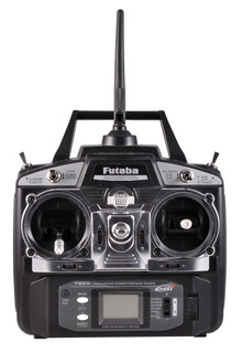 |
6-channel RC transmitter. |
|---|
A related concept is servo reversing, which allows the pilot to change the direction a servo moves for the same transmitter control input. In the normal state, the mechanical setup might happen to make the plane go left when the control stick is moved right; “reversing” the channel, typically through a small switch on the transmitter, will correct the problem.
Since the transmitter serves as the operator’s user interface, it can have any number of extra features to allow for more advanced control, such as how far a servo travels for a given deflection of the control input or allowing one control input to control multiple channels. The point to keep in mind is that all of these features just change how the transmitter interprets the user’s inputs, and changes nothing as far as the receiver or servos are concerned. One way to help understand this is to consider the case when you might need servo reversing as described in the previous example: your plane goes right when your control input goes left. If you didn’t have servo reversing, you could imagine removing the control stick from the transmitter, turning it 180 degrees, and putting it back in: left and right will now work properly, and nothing else in the transmitter or plane had to change.
There is a lot more to RC transmitters, such as frequencies and modulations schemes, but those are not particularly relevant to using servos by themselves or to understanding the context of their intended application.
2. Receiver
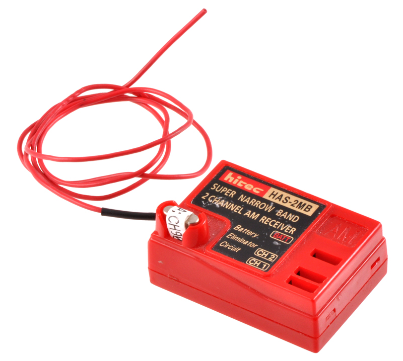 |
2-channel RC receiver. |
|---|
The receiver is the central component in the remote end of the RC system: it receives the radio signals from the transmitter, decodes them, and distributes corresponding commands to servos. Power for the servos is also routed through the receiver. Receivers must be matched to their transmitters to allow for multiple systems to work simultaneously without interference; the details of the radio communication from the transmitter to the receiver are beyond the scope of this discussion. The important thing to note is that when we use servos as general-purpose actuators outside of the standard RC framework, we must substitute something for the receiver to tell our servos what to do.
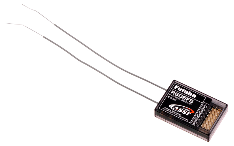 |
6-channel RC receiver. |
|---|
Like transmitters, receivers are made for a particular number of channels, and receivers are equipped with a corresponding number of ports for connecting servos. The number of channels on a transmitter and receiver do not necessarily need to match, but the number of channels that can actually be controlled will be the lower of the two channel counts. A six-channel transmitter will periodically send out commands with positions for all six channels; the receiver picks up those commands and sends the channel one position command to the channel one servo port, the channel two position command to the channel two servo port, and so on.
The receiver also has a connector for applying power, which is used by the receiver and also supplied to the servos. For small receivers where size is an important consideration, the power connection is often combined with the connection for one of the servos.
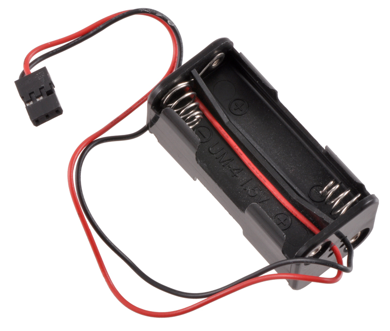
3. Receiver battery
The receiver and servos are powered by the receiver battery. Most of the power from the battery goes to the servos, so the battery must be sized to match the load the servos draw and to supply that current for a reasonable time. Low-end RC systems are sometimes supplied with a battery holder for four AAA or AA cells; using alkaline cells leads to a nominal voltage of 6 V, and using NiMH or NiCd rechargeable cells provides a nominal voltage of 4.8 V. The other common option is a battery pack of four or five NiMH or NiCd cells, which provides a nominal voltage of 4.8 V or 6.0 V, respectively. A higher voltage allows servos to provide more torque and speed, but some servos (typically very small ones) cannot withstand the higher voltage.
|
|

Higher-capacity batteries tend to be larger and heavier than lower-capacity batteries, so the there is a tradeoff of remote system performance (especially in model aircraft) and battery life. However, the servos are usually used intermittently and do not need to strain much, so it is generally easy to achieve a battery life of several hours, which is usually much longer than the operator would want to operate the model and longer than most fuel supplies last. In the case of electric-powered models, a much larger battery is used for the main motor, whether it drives a propeller or drive wheels, and there are systems (often called “battery eliminator circuit”, or BEC) for using this primary battery for the receiver and servos.
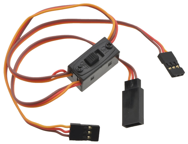 |
12" (30 cm) servo switch harness. |
|---|
Somewhat related to the receiver battery is the receiver switch harness, which is used between the battery and receiver to allow the remote system to be turned off. For some weight- or space-constrained applications, the switch might be omitted, and plugging in and unplugging the battery would be the only means of turning the system on and off.
Because radio control systems are designed to have the remote end unconstrained by power connections, there is no standard alternative to using a battery, whether it is a battery just for the radio system or a battery powering the whole model. Batteries are good power supplies for large and varying loads like the ones servos present, and finding economical alternatives to battery power can be difficult.
4. Servos
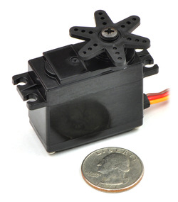 |
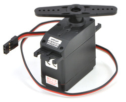
Standard-size servo. |
|---|
Servos are the actuators in the standard RC system: they take the command from the receiver, use the electrical power from the battery, and physically move. The vast majority of servos have rotary outputs that move through a bit less than 180 degrees, though there are some specialty servos with linear outputs (the output moves straight back and forth, rather than rotating) and outputs that can turn a full rotation or more. What makes a servo a servo is that it takes care of getting the output to the commanded position by monitoring the output and applying power accordingly: if you push against a servo, it will push back to try to maintain its position. We will explore the details of what is inside a servo later.
Servos tend to be black plastic boxes with similar proportions, with the output shaft protruding on only one end, a 6-inch to 12-inch cable for connecting to the receiver protruding out the other, and mounting tabs along the sides. Some high-performance servos have metal cases for improved heat dissipation, and some servos have transparent cases. A “standard” servo has dimensions similar to those indicated in the following diagram:
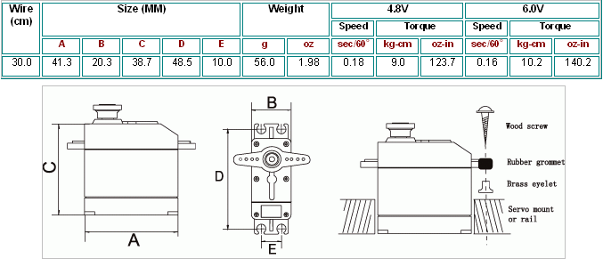 |
This particular diagram is for a high-torque servo with metal gears, so its weight and output torque are higher than that of most standard servos, which might weigh around 1.5 ounces and provide around 40 ounce-inches of torque at a speed of about 0.2 seconds per sixty degrees. Standard servos are commonly used in 1/10 scale cars and model aircraft that weigh a few to a dozen pounds. Larger, “giant scale” or “1/4 scale” servos are available for larger cars and aircraft that might weigh several dozen pounds. Micro servos were initially around half the size and weight of standard servos, but improvements in electronics and manufacturing have led to even smaller, “sub-micro” servos that might weight less than a tenth of a standard servo. These servos are typically used in very light aircraft intended for indoor flight.
The following picture shows all components of the remote side of an RC system connected together. Giant, standard, and sub-micro servos are included to show their relative sizes, though it would not be common for these three sizes to be used together in a real installation.
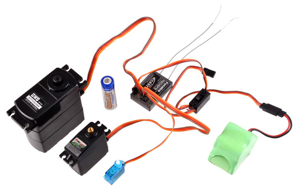 |
RC remote setup showing giant, standard, and sub-micro servos, receiver, receiver battery, switch, and AA cell for size reference. |
|---|
Servo connectors have become much more standardized lately, so most servos are interchangeable (unlike transmitters and receivers, which use various frquencies and modulation schemes that are not interoperable). The vast majority of servos use 3-pin connectors with 0.1"-spaced pins and with identical pin assignments; the most common difference is in the polarizing method of the plug (designed to prevent plugging in the servo backward) and the wire color scheme.
Common servo specifications
The primary performance specifications for servos are torque, speed, weight, and size:
- Torque – In many applications, torque is one of the most important considerations. Generally, larger servos offer more torque, but expensive servos that use exotic materials can offer more torque without giving up any other features. Within a given size and price, some trade-off between torque and speed is usually available. Some manufacturers might just use completely different item numbers for different performance points; others might use a base model number with suffixes like “T” or “XF” to indicate the “high-torque” and “extra-fast” versions of otherwise identical servos. Standard servos typically provide forty to a few hundred ounce-inches; giant servos can get past 500 ounce-inches, and the smallest servos provide less than ten ounce-inches.
- Speed – Servo speed is usually specified in what might seem to be an odd manner: the time required to move sixty degrees. More generally common units for speed are rotations per second or rotations per minute (RPM), but those are not so useful for a device that does not make full rotations and spends a lot of its time accelerating. (If using a time for “speed” makes you uncomfortable, think of 100-meter sprinters: we report their performance in seconds, not miles per hour.) A typical servo speed is around 0.15 seconds per 60 degrees; less than 0.1 seconds is quite fast, and more than 0.25 seconds is noticeably slow.
- Weight – Weight is strongly correlated to output power (which is the product of speed and torque); going to higher speeds or higher torques (without corresponding drops in the other) will generally mean more weight. Standard servos weigh 1.5–2 ounces, giant servos can weigh five ounces or more, and micro servos weigh half an ounce or less. Small servos tend to use shorter and thinner wires to save weight.
- Size – Most servos have the same general shape, and the size generally scales with the output power and weight. However, there are some servos with noticeably different aspect ratios. These tend to be designed for specialty applications such as retractable landing gear or fitting in thin wings.
There are other specifications that cover aspects like materials used in the gears and the technology of the internal motor or electronics, but I’ll leave those for another post. There are also many other parameters that robot builders might want to know but which are not specified; at least some of these missing specifications are because of the servo’s intended use.
Ramifications of the servo’s intended use
While servos are great for their intended use, they have shortcomings as general-purpose actuators. It can be frustrating that there are thousands of different servos that all have the same limitations, so before wasting time looking for a servo that doesn’t exist or denouncing a hobby store for not carrying it, it’s good to consider why some things that matter to a robot builder might not matter to the RC hobbyist.
- Lack of feedback – Probably the most disappointing shortcoming of regular servos is that they provide no feedback. Since the main feature of a servo is its ability to get the output to the commanded position, it must know the output position, which could be very good information for other parts of a robot. Roboticists might want their servos to report all kind of other things, like how hard the servo is exerting itself to maintain a position or if there has been some kind of fault in the servo. Unfortunately, the basic paradigm of one-way communication from the radio control transmitter to the receiver means that even if a servo could somehow tell the receiver something, the receiver would still not be able to communicate that back to the remote operator, so there is no incentive for normal servo manufacturers to address this limitation.
- Twitch on power-up – A subtle problem related to the lack of feedback is that there must be some first command that a servo receives after being turned on. Since there are no commands for limiting speed or power, if the output shaft is not already in that commanded position, the servo will instantly try with all its might to head for the position. This doesn’t really matter if it means a twitch in an airplane flap when it is turned on, but it can be quite dangerous for a robot arm or leg made of servos since trying to jerk a more massive mechanism could put a lot more stress on the servos. To limit the effects of this problem, it can be helpful to have a power-down position that the mechanism is put in before cutting power; on power-up, the first command can be to go to that position, and ideally, the mechanism will still be in that position and thereby minimize any self-destructive twitch. (Subsequent commands can move the servo slowly by sending position commands that are very close to each other, but there is no way of guaranteeing that the first command is for a position close to where the servo already is.)
- Limited rotation range – The standard rotation range being too limited is probably the second most common lament I have heard. With the exception of a few specialty applications like model sailboats, most radio control model applications just don’t need more than about ±60 degrees of range. Most servos have about 150 to 200 degrees of range, so from the perspective of the manufacturers, that is more than enough for the necessary 120 degrees, and the exact limit on the range is usually not even specified. That can be quite annoying for a person who really wants a guaranteed 180 degrees.
- Low operating voltage – A relatively low operating voltage is a great feature for a system intended to use a few servos wirelessly for an hour at a time or less. It’s less convenient for a hexapod walking robot or a continuously operating but stationary animatronic puppet since the low voltage means more current is needed for the same amount of power. If you want to use twenty servos at once, you need a 20-amp power supply, which is not necessarily cheap, and you need fairly thick wires to handle the current efficiently.
- Short servo cable length – A requirement that servos be within a few feet of each other is not much of a limitation for a model whose largest dimension is not much more than that. It’s tempting to use servos in larger-scale projects, but the low operating voltage and the command protocol used is not appropriate for just using longer wires. If you have a project in which you want servos spaced every ten feet or more, you will likely need to have some extra electronics at each servo so that the distance from the servo to the device it is plugged into is not more than a few feet.
- Current not specified – Since the currents used by servos are typically low enough, they are generally not specified. The problem is that a “low enough” stall current can add up if you have twenty servos straining at once, and a “low enough” idle current might not be low enough if you want to make a device that is powered all day but only needs to move at dawn and dusk. Part of the problem of the currents not being specified is that even if somebody helpful at Pololu measures one servo for you, you can’t know how representative that is of the particular servo you will receive. (This is not an indictment of servo quality: for instance, all units of one servo model might be under a manufacturer’s internal specification of 25 mA idle current; if we test one and it happens to be 5 mA and your servo is 15 mA, they are both good and close enough to zero for the intended use even though your unit is three times worse.) If you really care about your servo currents, you have to measure them yourself.
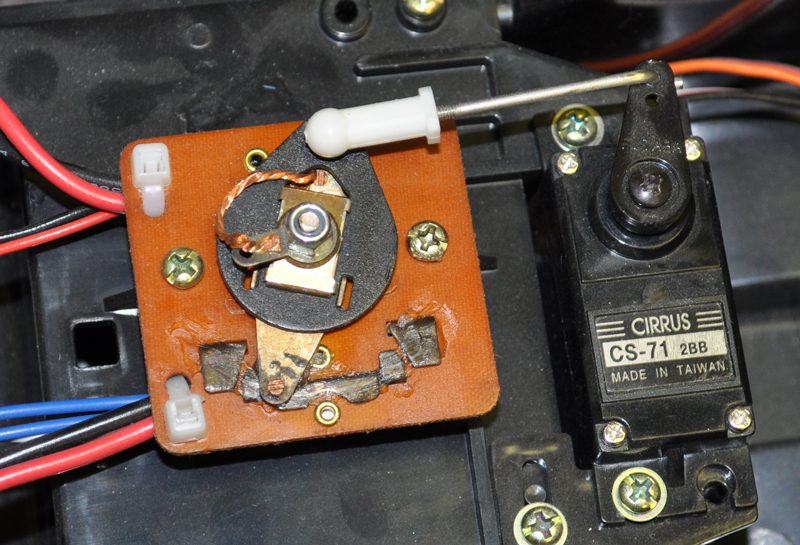 |
Servo connected to a mechanical speed control. |
|---|
- Output shaft on only one side of servo – Normal servos made for the RC market have a short output shaft protruding on only one side of the case. The shaft is connected to an arm that usually pushes or pulls on some linkages, and having the shaft protrude from the other side would make the servo larger and more difficult to manufacture without much benefit for most of the intended customers. The one-sided output is not ideal for many robotics applications, and some specialty manufacturers offer brackets to enable creation of complex joints.
- Not designed for backdriving – Airplane modelers aren’t really clamoring for a feature whereby they can pose their airplanes’ control surfaces and have them “learn” the positions. (This is also related to the above mentioned limitation of no feedback.) Robot designers, on the other hand, might want to externally manipulate their creations. Unfortunately, most servos are not made for that, and some servos, especially the sub-micro ones with itty bitty gears, can reliably break if you try to back drive them (even when power is not applied).
- Audible noise – This might matter more to magic trick and kinetic sculpture creators than to most hobby robot builders, whose robot was never realistically going to be able to sneak up on the cat, anyway. Unfortunately for those looking for quiet servos, radio control folks using servos in models with loud engines and operating hundreds of feet away don’t really care about how loud a servo is.
- Limited response or update rate – Servos are designed for real-time remote operation by humans, for which the standard update rate of fifty times per second is more than adequate. However, that might seem kind of slow for an autonomous robot which might be capable of updating its calculation of the desired servo position several hundred times per second. There are some servos, usually intended for use in conjunction with a gyro or other sensor on model aircraft, that can handle faster command rates.
- Limited options for larger servos – Servo manufacturers keep introducing newer servos, but the advancements tend to be in making micro servos smaller or in improving performance in standard servos. The same is not true for giant servos. Existing giant servos are already big enough for models with twelve foot wingspans and costing thousands of dollars, so there probably is not much of a market for even bigger servos. Also, the low-voltage limitation becomes a bigger problem the bigger a servo is and the more power it needs, so really big servos need some alternative and less standardized way of being powered.
Specialty robotics servos
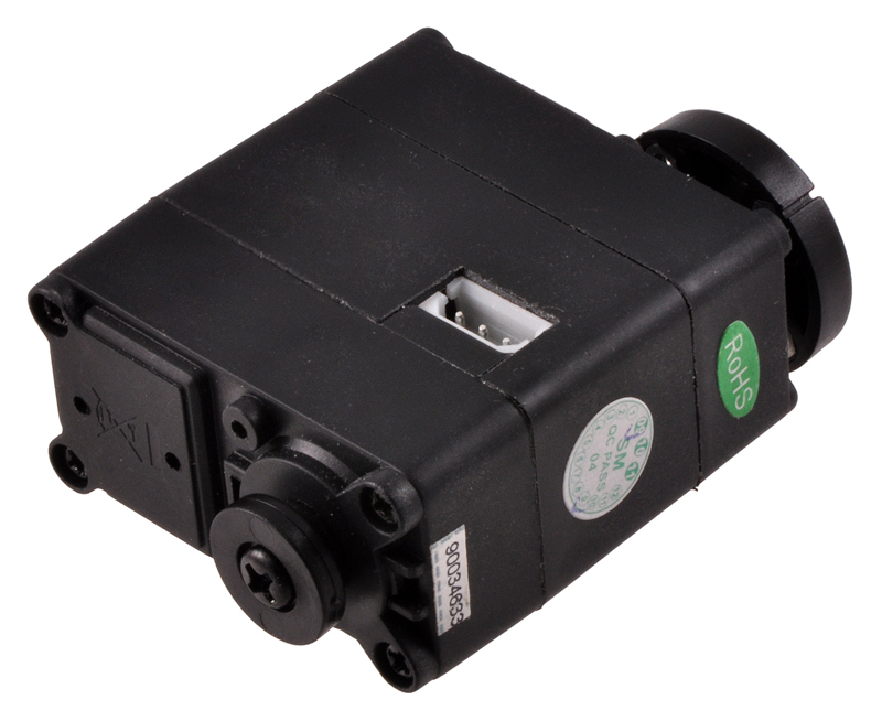 |
Servo developed specifically for robotics applications. |
|---|
Traditional servo manufacturers and manufacturers focusing on robotics have addressed most of the limitations listed above by developing specialized servos that have custom interfaces that allow for feedback and more advanced commands. Unfortunately, the extensions to the basic RC servo tend to be proprietary, so there is less to say about them in a general sense. Therefore, although those servos are made for robots and this series of articles is about using servos for robots, I will focus on traditional, standardized hobby servos. Most of the general information I provide should be relevant to robot servos, too, but keep in mind that if I mention some limitation of servos, there’s probably some specialized robot servo out there that tries to address the limitation.
Conclusion (for now)
I hope this has provided some context for where servos come from and how they are normally used. Next up: just servos: what’s inside, and how they work.
-
One-Million-Color Flashlight
- 10 January 2011Two ShiftBrites controlled by Mini Maestros power a flashlight capable of displaying one million colors with many interesting modes of operation....
-
Gettin' all up in your servos
- 21 January 2011Having introduced servos and their role in a typical hobby radio control application, I will now focus on the servo itself: its parts, what is...
8 comments


Did you look at the post about multi-turn servos?
http://www.pololu.com/blog/24/continuous-rotation-servos-and-multi-turn-servos
In general, it's pretty difficult to change a normal servo to a multi-turn servo; at the very least, you need to change your feedback potentiometer to a multi-turn pot or change the gearing to it somehow.
I do not know what you mean by the "in one direction" part. If it can go more than 360 degrees and keep track of position, it will be able to do that in both directions.
- Jan

This is not a very good place to ask a question like that (anyone reading this post is likely new to servos and unlikely to have meaningful experience with a particular servo you are considering).
Anyway, while I have heard of no problems with that servo and think it's generally decent, if it were my $1000 plane, I would probably put some higher-end servo in there. At least for critical control surfaces.
- Jan

Your question has nothing to do with servos, but briefly: cheap RC toys often have separate frequencies, like 27MHz and 49MHz, to avoid interference. More sophisticated RC systems use several dozen channels in the 72MHz and 75MHz frequencies, and you have to use different channels if you want to prevent interference between multiple systems operating at the same time and place. There are also rules about which frequencies can be used for surface models and which can be used for aircraft; these things can all vary by country. Newer 2.4GHz spread spectrum systems automatically jump around several channels, so multiple systems are not supposed to interfere with each other (you will have to do some kind of "binding" process so that a particular receiver knows which particular transmitter to listen to).
- Jan


Additionally, if you are having problems understanding servo pulse, you can learn more about them in this blog post: http://www.pololu.com/blog/17/servo-control-interface-in-detail
-Derrill
Post a comment


Home | Forum | Blog | Support | Ordering Information | Lists | Distributors | BIG Order Form | About | Contact
© 2001–2026 Pololu Corporation


