Pololu Blog » Engage Your Brain »
Electrical characteristics of servos and introduction to the servo control interface
 |
So far, I have been talking about servos largely from the perspective of their typical use. While I hope I have provided a decent foundation about their intended use and some idea of what is inside a servo, these are things you could learn from hobby stores and taking apart a few servos. Today, I want to move on to a discussion of the electrical characteristics of servos, with the control interface as the primary topic. From the servo manufacturers’ perspective, the control signal can be an internal detail, so discussing it means we are moving on to a realm that is less officially documented. I will try to keep things general and back up my claims a bit where practical, but some details might not apply to all servos.
Electrical connection
First, a review of the electrical connections that I mentioned in the inside servos post. If you just read that, you can jump ahead to the “power” section.
Servos have three-wire cables that supply power and commands to servos. The cables are typically six to twelve inches long, with 22 gauge and thinner wires (smaller servos tend to have shorter and thinner wires). Since the connectors have become more standardized, the order of the wires has also become standardized, with the power wire in the middle flanked by ground and signal wires. However, the color schemes still vary. Common ones are:
- Black for ground, red for power, white for signal
- Brown for ground, red for power, and orange for signal
- Black for ground, red for power, blue for signal
My preference is for the first scheme since that offers the most contrast; the orange and brown of the second scheme can look kind of similar with bad lighting, as can the blue and black of the third approach. You are almost guaranteed to instantly destroy a servo if you connect power backwards, so make sure you double-check your connections.
The three-conductor cable is terminated with a 3-pin connector, which is almost universally a female connector with 0.1" spacing. Unfortunately, much of the RC world calls this female connector a male connector. As with the cable colors, the connector colors can vary. The “Futaba” plug, on the left in the picture below, has an extra polarizing tab (on the left side in the picture) that can be cut off to match the others, which are called “JR” (center) and “Airtronics Z” (right). Some of the brand names might vary by country; the most common names I see from generic servo makers in China are “Futaba” and “JR”.
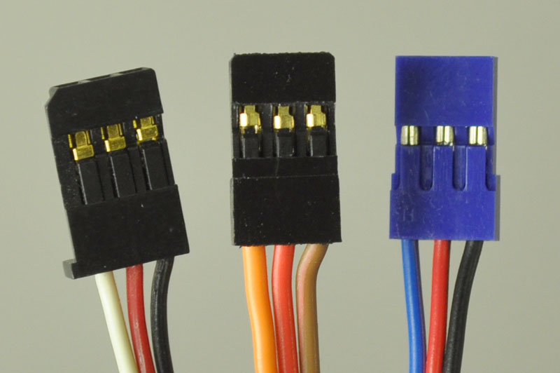 |
Common RC servo connectors. From left to right: Futaba, JR, Airtronics Z. |
|---|
Viewed from the end, the connectors have two beveled corners to help prevent plugging servos in backwards. That prevention mechanism relies on the RC receiver having a corresponding cutout, which is not present on most servo controllers and other electronics a robot builder might be using instead of the usual radio control components. Again: pay attention when plugging in your servos!
Power
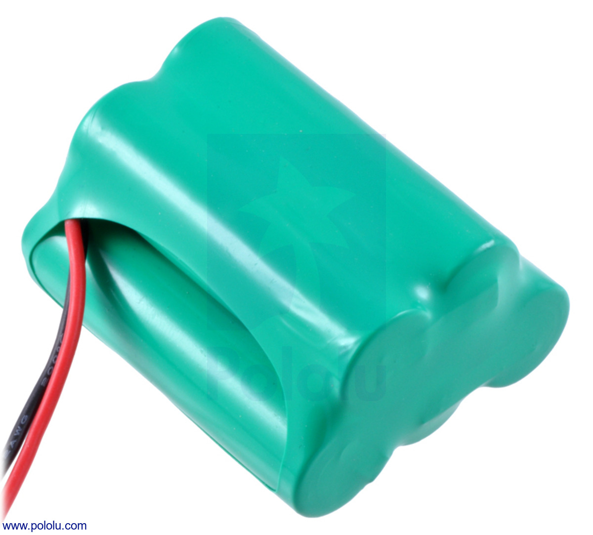 |
Rechargeable NiMH battery pack: 6.0 V, 2200 mAh, 3+2 AA cells. |
|---|
As I mentioned in the introduction to servos, servos are typically used in battery-powered applications. The batteries were historically four- or five-cell NiCd packs or four-cell alkaline packs, which yield nominal voltages of 4.8-6.0 V. Newer NiMH packs have the same voltages, and so servos tend to be designed for operation at those voltages but without specification of the exact operating range. A well-charged 5-cell pack can reach about 7.0 V, and a 4-cell pack can drop to about 4.0 V without being considered ridiculously discharged, so that is the range over which we can reasonably expect most servos to operate.
Going to higher voltages can destroy servos, so testing the upper boundary can be risky. On the other hand, lower voltages correspond to drained batteries that we hope would not lead to damaged servos, so you can safely test the lower end of the operating range with a variable power supply. If you do tests for the low end, keep in mind that individual units can vary and that the limit might be a function of variables such as the temperature.
 |
The smaller, 1/3- and 2/3-AAA NiMH battery packs are great for miniature robots. |
|---|
Some servos, especially micro servos, are rated only for 4.8 V operation, which implies 4-cell operation with a maximum voltage of 6.0 V. As the RC industry embraced lithium-based rechargeable batteries, some servos intended for operation from one cell (3.7 V nominal) and from two cells in series (7.4 V nominal) emerged. The single-cell units are again on the micro side, and can have upper limits of around 4.5 V; the two-cell units might be marketed as high-voltage servos since the upper voltage limit is 9 V or higher. A three-cell nickel-based pack can generally replace a single-cell lithium battery, and a six-cell nickel pack can replace a two-cell lithium pack.
The current required by servos also tends to be unspecified. When we design with servos, as with most components, there are two main currents we care about: the quiescent or idle current, when the servo is not doing anything, and the maximum current, which in the case of a servo is the stall current. The quiescent current will give us an upper bound on how long a battery-powered application can run; the stall current tells us the minimum current our power supply has to be capable of delivering. The average current a servo consumes in actual operation will be somewhere between the two extremes and will depend on how active the servo is in the application.
The current a servo draws will be approximately linear with the supply voltage, so the currents drawn at 7 V will be almost double those at 4 V. It’s relatively easy to measure the quiescent current since it is low, constant, and flows in a low-strain scenario. Stall currents are more difficult to measure because actually stalling a servo is not that desirable, so we do not want to do it for a prolonged period. If you need to know the stall current, it’s safest to measure at the low end of the operating range and then extrapolate for higher supply voltages.
Since servo currents usually are not specified and we might not want to bother measuring each servo we use, it’s good to keep a few estimates in mind. A standard servo will have a stall current around one amp, a micro servo will need a few hundred milliamps, and a giant servo can draw ten amps or more. Since servos run at basically the same voltages, the only ways servos can offer more torque is to have higher gear ratios or to use more current. If two servos have similar speeds at the same voltage but one has five times the stall torque, it will likely draw five times the stall current.
The quiescent currents are tricker to estimate because they are not dominated by the motor the way stall currents are. There can be substantial variation in these idle currents since they depend on the electronics in the servo, but typically, the current should be in the few dozen to one or two hundred milliamp range. The quiescent current can also be complicated by the existence of two possible values: one for the case where the servo is trying to maintain a position but is already there and therefore doesn’t need to power the motor, and another for the case where the servo is “off” and not trying to maintain a position at all. (We’ll get to what it means for the servo to be “off” later.)
Servo control interface
Servos are controlled by pulses on the signal line that are referenced to the ground line, which is the return path both for servo power and the control signal. The pulse frequency is typically 50 Hz, but the exact frequency does not matter. The pulse width corresponds to the position of the servo, with 1.5 ms corresponding to the servo’s “neutral” point. This neutral point is not necessarily the midpoint of the servo’s maximum available range. Making the pulse shorter makes the servo go one way; making the pulse longer makes the servo go the other way. The normal pulse width range is 1.0 ms to 2.0 ms, which corresponds to an approximate mechanical range of 90 degrees (for most servos).
Since the servo interface is not that explicitly documented, let’s look at the signals from a typical RC receiver on an oscilloscope. We’ll begin by looking at this low-end, 2-channel AM receiver:
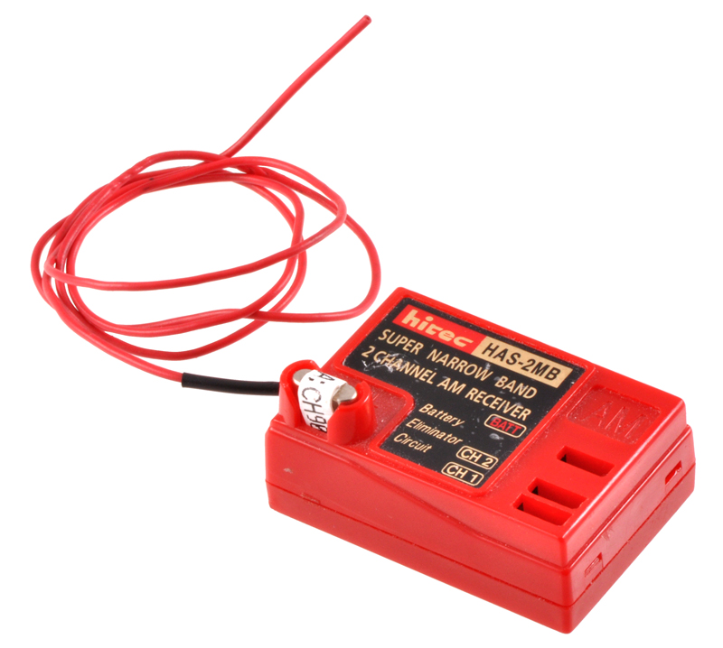 |
2-channel RC receiver. |
|---|
The following screen shot shows the signals for the two channels over a 100 ms period. I powered the receiver with a 5-cell battery that should have been somewhere around 6 V, but we see the output pulses are regulated to about four volts:
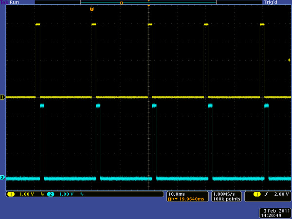 |
100 ms oscilloscope screen capture of two channels from a 75 MHz RC receiver. |
|---|
At this horizontal time scale, we can see that the pulse frequency is actually very slightly higher than 50 Hz. We also see that a 1.5 ms pulse represents less than 10% duty cycle, so we have to zoom in in time to better see the actual pulses:
|
|
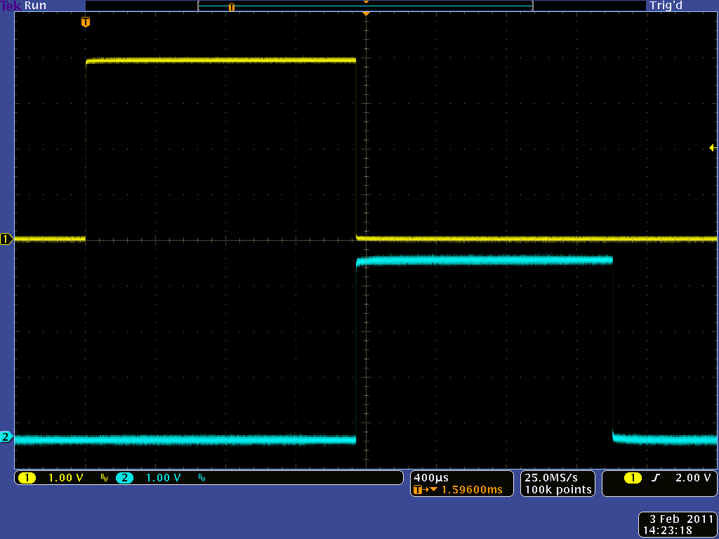

In the left picture, both channels are at around 1.5 ms since I had the control inputs on the RC transmitter at their neutral positions. In the right capture, I’ve moved the control inputs to their extremes, causing the channel one pulse width to get to almost 2 ms and the channel two pulse width to shrink to about 1 ms.
Next up, let’s look at the outputs from this higher-end, six channel receiver:
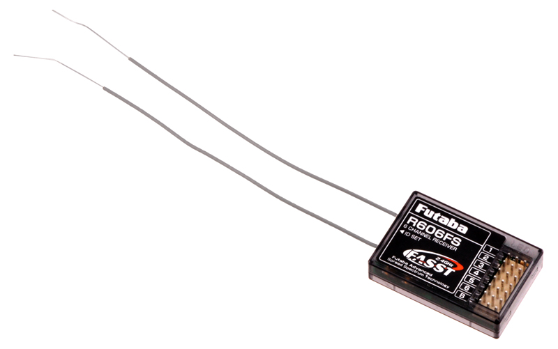 |
6-channel RC receiver. |
|---|
We’ll start again with the same 100 ms horizontal scale, which shows that the pulse frequency from this receiver is a bit higher than from the previous receiver:
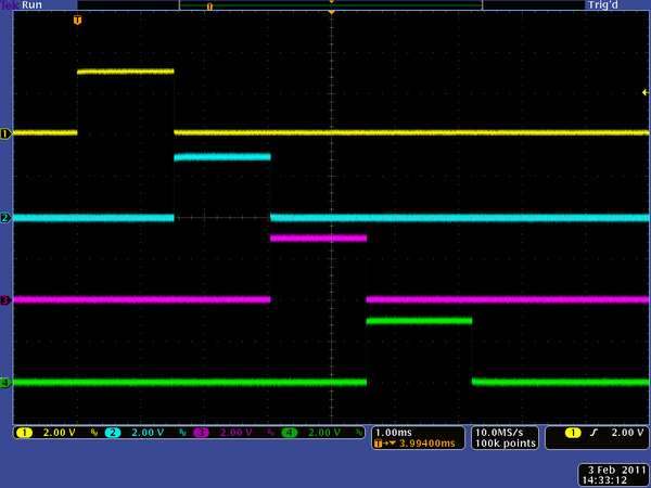
 |
100 ms oscilloscope screen capture of four channels from a 2.4 GHz RC receiver. |
|---|
It’s difficult to notice since I had to change the vertical scale to fit four channels, but the pulse amplitude is now down to just 3 V. If we zoom in in time, we can also clearly see that the pulses are getting sent out one after another:
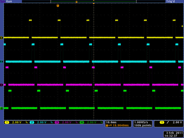
 |
10 ms oscilloscope screen capture of four channels from a 2.4 GHz RC receiver. |
|---|
The relative timing of the pulses on various channels does not matter to individual servos since each servo only gets one signal, but it does give us something to think about if we want to generate the pulses to control multiple servos: if we want to send more then ten pulses that can be up to 2 ms long in 20 ms or less, we will have to keep track of multiple simultaneous pulses. I looked at another RC receiver (an 8-channel Airtronics 92824) hoping it would have overlapping pulses, but the outputs looked the same as those from the Futaba receiver (including the 3.0 V pulse voltage).
Conclusion (for now)
At this point, you should have some idea about the power and signal you need to apply to a servo to get it to move. Next time, we’ll look at servos and their command interface in more detail to see what happens as we try to get more performance out of them.
-

Snow-Boarduino 4WD robot
- 1 February 2011We found this robot pictured on the Adafruit forums driving through some snow. It was made with a TReX, a 4WD Wild Thumper, and a Boarduino.
-
Home-made m3pi robot controlled by Bluetooth keyboard
- 3 February 2011This project by Kazuhiro Ouchi (in Japanese) shows a 3pi robot with an ARM mbed controlled by Bluetooth keyboard.
15 comments


As I wrote in the next article, I am not a fan of calling the servo control signals PWM. The stuff I've presented is all about the signals going to the servos, which is all you should have to care about if you are controlling them from a microcontroller.
I think what you are asking about is PPM (pulse position modulation) vs. PCM (I think the C is for "code", not "controlled"), and that has to do with how the radio and receiver communicate. With PPM, the servo positions are sent as varying pulse widths in a more analog way in the sense that if you have a 1.5 ms target pulse, the radio will do something with its signal (e.g. change amplitude or frequency) for that 1.5 ms. With PCM, the positions are sent digitally, so there will be a set resolution, like 10 bits (1024 possible positions), and the 1.5 ms target pulse would get communicated as the digital number 512 getting sent through some more complicated encoding than in the PPM case. Either way, though, the receiver will deal with all that and send the same 1.5 ms pulse described in these articles to the servo.
- Jan

Yeah, but your servos might cut out if you strain both servos at the same time. If you're also powering whatever is controlling the servos with the same source, you might have bigger problems with power dropping low enough to reset your device, in which case you should power that separately or just get a power supply that can supply more current. You should also measure your adapter output to make sure it's actually close to 5V at no load and with the servos doing something.
- Jan

Relating to the RC example above, I have an RC system (Kyosho Mini Inferno) where the combined ESC-receiver unit connects to the servo using 4 cables instead of the usual 3. Cables are red / black / orange / white and on the controller PCB the white and orange are connected together by a small capacitor. This seems to be a custom dedicated setup for this particular model, it's the only 4-cable RC servo I'm aware of.
Would you have any idea why a 4th cable would be used? It makes it a pain to replace any one component, as you end up needing a completely new electrical system.
thanks
- Jan

I know that post is very old, but I need to ask:
How much current the signal line draw? I can put a 1,2k Ohm resistor in serie between the SIGNAL (5V) and GROUND?
Your question is not clear. If you are asking about characteristics of servos, as in can you stick 1.2k in series between your RC control signal and the servo (NOT between signal and ground, which would be in parallel with the servo), it's a little more than I'm comfortable with (I would use something like 220 ohms) but should probably be fine. Things like the particular servo you have and the wiring lengths will matter, so you should try to look at the signal on the servo side with an oscilloscope to make sure it looks decent.
If you are asking about the characteristics of receivers or other servo controllers, as in can you put a 1.2k resistor in parallel (NOT series) between signal and ground, that will depend on your receiver, and 1.2k is a little on the small side (I would use about 10k for a pull-down resistor). You can again look at the signal with an oscilloscope to see if the resistor is deforming the signal too much.
- Jan


This is not something to calculate (if you trusted your battery capacity, you could do some calculations based on how long it lasts, but you could only do that for lighter loads since forcing your servo to some max load scenario for a prolonged period would likely destroy it). So, you should just put a current meter in line with your servo and see how much it draws. That would typically show you average current over maybe a tenth of a second or however fast your meter updates. If you want to see the faster peaks, you would need to use an oscilloscope.
- Jan


-Claire

My question is where does the power source wire from the ESC connect on the receiver ? One of the receivers had a dedicated unlabeled slot for the power wire, the other three do not, but instead have a BEC next to the slot at the top. Is this where the receiver wire from the esc plugs in ? With the number one slot used for the servo , where is the receiver wire plugged in ?
The problem is that although the rudder servo works perfectly, the motor is dead, the forward and reverse do not work at all--I also need to know when connecting the power to receiver wire, did I read that the yellow or orange colored wire is closest to the main body of the receiver ? Could my problem be that I didn't get the "binding" right ? The components I have, do not match the diagrams in my transmitter instruction book and there are two different ways to bind the unit and receiver, not sure which is right--as stated no matter what the servo works great, so I don't think it's damaged.
I have checked and rechecked my connections and can not anything that isn't solid, nothing is loose and the motor runs fine with direct current -- if the binding the transmitter to the receiver is not right, could that be the problem or if that is the case, would the servo still work ? Would you have any idea what I'm not getting right ? Thank you for any help you can give-- John

Unfortunately, the comments for this blog post are not a good setting for troubleshooting like this. Instead, you might consider making a post on our forum:
https://forum.pololu.com/
However, it sounds like you might not be using any of our products. If that is the case then the help we can offer is probably limited, so you might have better luck posting to a hobby RC focused forum.
- Patrick
Post a comment


Home | Forum | Blog | Support | Ordering Information | Lists | Distributors | BIG Order Form | About | Contact
© 2001–2026 Pololu Corporation


