Support »
Pololu Dual G2 High-Power Motor Driver Shields for Arduino User’s Guide

View document on multiple pages.
- 1. Overview
- 2. Contacting Pololu
- 3. Included components
- 4. Board connections
- 5. Programming your Arduino
- 6. Dimensions
1. Overview
 |
The G2 family of dual high-power motor driver shields features pairs of discrete MOSFET H-bridges designed to drive two large brushed DC motors. They have the form factor of an Arduino shield, so they can plug directly into an Arduino or compatible board, such as the A-Star 32U4 Prime, but they also break out all of the motor driver pins along the left side of the board to enable use as a general-purpose motor driver without an Arduino. Four versions are available so you can pick the one with the appropriate operating voltage range and output current capabilities for your project:
 Dual G2 High- Power Motor Driver 18v22 Shield |
 Dual G2 High- Power Motor Driver 18v18 Shield |
 Dual G2 High- Power Motor Driver 24v18 Shield |
 Dual G2 High- Power Motor Driver 24v14 Shield |
|
|---|---|---|---|---|
| Absolute max input voltage: |
30 V | 40 V | ||
| Max nominal battery voltage: |
18 V | 28 V | ||
| Max continuous current per channel: |
22 A | 18 A | 18 A | 14 A |
| Default active current- limiting threshold: |
60 A | 50 A | 40 A | |
| Current sense output: |
10 mV/A | 20 mV/A | ||
The minimum operating voltage for all four versions is 6.5 V. The maximum operating voltages are given in the above table; they are well above what typical Arduinos can tolerate, so the shields include an integrated 7.5 V, 1 A switching step-down regulator that can optionally be used to power whatever Arduino or Arduino-compatible board it is plugged into, enabling operation from a single power supply. This regulator can also be configured to output 5 V for applications where that would be more useful than the default 7.5 V, and the Arduino pin mappings can all be customized if the defaults are not convenient.
Features and specifications
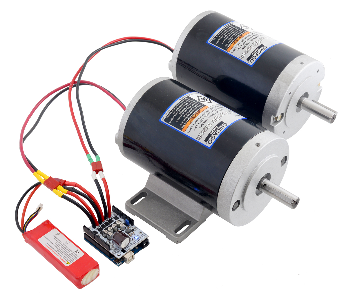
 |
Pololu Dual G2 High-Power Motor Driver Shield being controlled by an A-Star 32U4 Prime. |
|---|
- Operates from 6.5 V to 30 V (18vX) or 40 V (24vX), depending on the version of the shield
- Inputs compatible with 1.8 V, 3.3 V, and 5 V logic
- PWM operation up to 100 kHz
- Motor indicator LEDs show what the outputs are doing even when no motor is connected
- Blue power LED is lit while the board is powered
- Active current limiting (chopping); default threshold depends on the version of the shield and can be adjusted lower by adding a resistor
- Reverse-voltage protection
- Undervoltage shutdown
- Short circuit protection
- Control interface allows for sign-magnitude or locked-antiphase operation
- Integrated 7.5 V, 1 A switching step-down voltage regulator (can be set to output 5 V instead)
- Can be used with an Arduino or compatible board (through shield headers) or other microcontroller boards (through 0.1″ header along the left side)
- Arduino library makes it easy to get started using this board as a motor driver shield
- Arduino pin mappings can be customized if the default mappings are not convenient
- When used as a shield, the motor power supply or 7.5 V regulator output can optionally be used to power the Arduino base for single-supply operation
2. Contacting Pololu
We would be delighted to hear from you about any of your projects and about your experience with the Dual G2 High-Power Motor Driver Shields for Arduino. You can contact us directly or post on our forum. Tell us what we did well, what we could improve, what you would like to see in the future, or anything else you would like to say!
3. Included components
This motor driver board ships with all of the surface-mount parts populated. However, soldering is required for assembly of the included through-hole parts. The following through-hole parts are included:
 |
Pololu Dual G2 High-Power Motor Driver 18v18 Shield for Arduino with included hardware. |
|---|
- one extended/stackable 1×10 female header (for assembly as an Arduino shield)
- two extended/stackable 1×8 female headers (for assembly as an Arduino shield)
- two extended/stackable 1×6 female headers (for assembly as an Arduino shield)
- three 2-pin 5mm terminal blocks (for board power and motor outputs)
- 40-pin 0.1″ straight breakaway male header (may ship in several pieces, such as two 20-pin strips)
- one 0.1″ shorting block (for optionally supplying shield power to Arduino)
3.a. Assembly for use as an Arduino shield
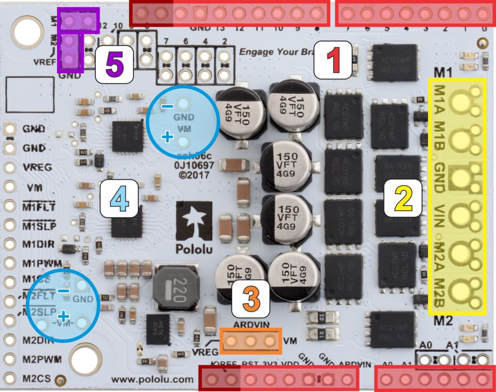 |
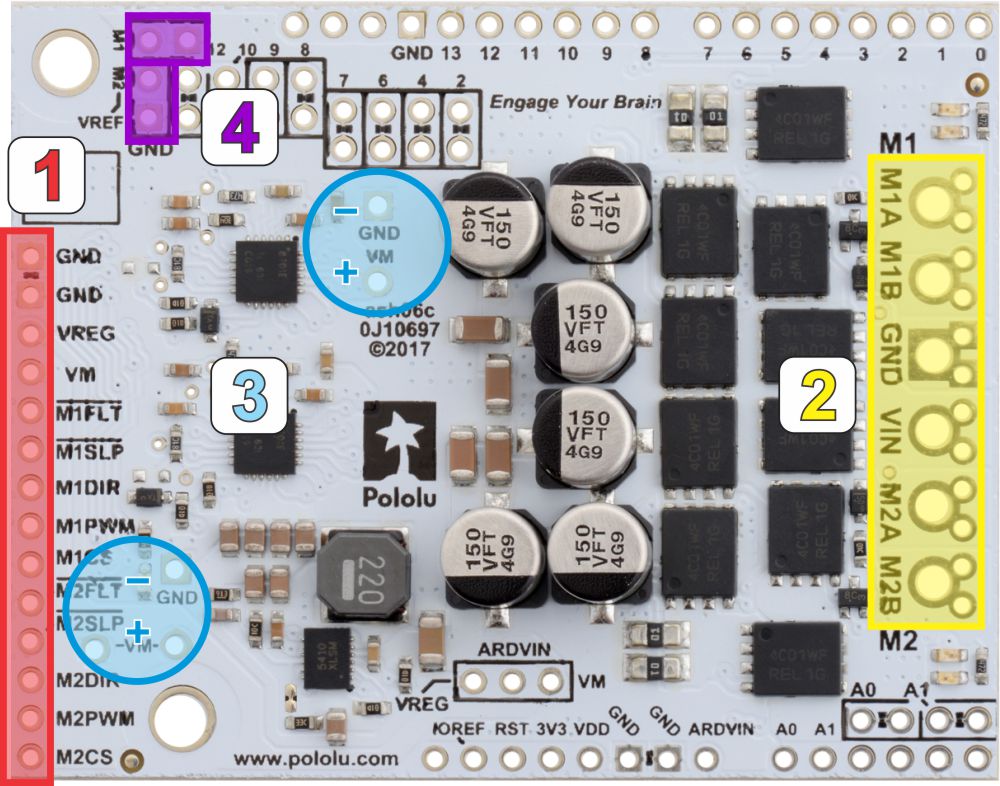
- Stackable Arduino headers: Before you can use this board as an Arduino shield, you need to solder four of the five included Arduino header strips to the set of holes highlighted in red in the picture above. The headers should be oriented so that the female sockets rest on the top side of the shield and face up while the male pins protrude down through the board, and the solder connections should be made on the underside of the shield. Newer Arduino boards, including the Uno R3 and the Leonardo, use one 1×10 header, two 1×8 headers, and one 1×6 header, as shown in the left picture below; older Arduino boards use two 1×8 headers and two 1×6 headers (the two pairs of pins highlighted in darker red should not be populated if you are using this board with an older Arduino that does not support these additional pins). Please make sure you solder the appropriate headers for your particular Arduino!
- Motor and power connections: The six large holes/twelve small holes on the right side of the board, highlighted in yellow in the above diagram, are the motor outputs and power inputs. You can optionally solder the included 5mm-pitch terminal blocks to the six large holes to enable temporary motor and motor power connections, or you can break off a 1×12 section of the included 0.1″ header strip and solder it into the smaller through-holes that border the six large motor and motor power pads. Note, however, that the terminal blocks are only rated for 16 A, and each header pin pair is only rated for a combined 6 A, so for higher-current applications, thick wires with high-current connectors should be soldered directly to the board. The smaller holes are intended only for 0.1″ header pins, not for the terminal blocks! Motor and power connections should not be made through a breadboard.
|
|
- Arduino power jumper: If you want the option of using a single power supply for your entire system (rather than powering the shield and Arduino separately), you can solder a 1×3 piece of the included 0.1″ male header strip to the pins highlighted in orange in the above picture. The middle pin connects to the Arduino’s VIN pin, and you can use the included shorting block to supply this pin with either VM (reverse-protected shield VIN) or VREG (7.5 V by default when the shield VIN is over ~8 V) to power the Arduino. The shield can accept voltages that are well above what typical Arduinos can tolerate, so we strongly recommend putting the shorting block in the VREG position for power supplies over 9 V.
You should not use this feature to power the shield from the Arduino as this connection is not designed to handle high currents, and you must never supply power to the Arduino’s VIN pin or power jack while this shorting block is in place, because it will create a short between the shield power supply and the Arduino power supply and will likely permanently damage something.
- Additional power capacitors: The motor driver includes six 100 µF or 150 µF electrolytic power capacitors, and the blue circles in the above picture show places where additional power capacitors can be added (e.g. to compensate for long power wires or increase stability of the power supply). Additional power capacitors are usually not necessary, and no additional capacitors are included with this motor driver.
- VREF: The default current limiting setting for the motor driver can be lowered by connecting a resistor between the VREF pins and the adjacent GND pins in the locations highlighted in purple in the above picture. For more details on adjusting the current limit threshold, see Section 4.b.
The other through-holes on the shield are used for more advanced things like customizing the Arduino pin mappings and are not necessary for getting started using this shield with an Arduino. They are discussed in more detail later in this guide.
3.b. Assembly for use as a general-purpose motor driver
 |
- Logic connections: The 14 small holes along the left side of the board, highlighted in red in the above diagram, are used to interface with the motor drivers. You can optionally solder a 1×14 piece of the included 0.1″ male header strip to these pins. Soldering the pins so they protrude down allows the logic side of the motor driver to be plugged into a standard solderless breadboard or perfboard, or they can be soldered facing up for use with custom cables. You can also solder 0.1″ female headers to these pins.
- Motor and power connections: The six large holes/twelve small holes on the right side of the board, highlighted in yellow in the above diagram, are the motor outputs and power inputs. You can optionally solder the included 5mm-pitch terminal blocks to the six large holes to enable temporary motor and motor power connections, or you can break off a 12×1 section of the included 0.1″ header strip and solder it into the smaller through-holes that border the six large motor and motor power pads. Note, however, that the terminal blocks are only rated for 16 A, and each header pin pair is only rated for a combined 6 A, so for higher-current applications, thick wires with high-current connectors should be soldered directly to the board. The smaller holes are intended only for 0.1″ header pins, not for the terminal blocks! Motor and power connections should not be made through a breadboard.
- Additional power capacitors: The motor driver includes six 100 µF or 150 µF electrolytic power capacitors, and the blue circles in the above picture show places where additional power capacitors can be added (e.g. to compensate for long power wires or increase stability of the power supply). Additional power capacitors are usually not necessary, and no additional capacitors are included with this motor driver.
- VREF: The default current limiting setting for the motor driver can be lowered by connecting a resistor between the VREF pins and the adjacent GND pins in the locations highlighted in purple in the above picture. For more details on adjusting the current limit threshold, see Section 4.b.
4. Board connections
4.a. Power
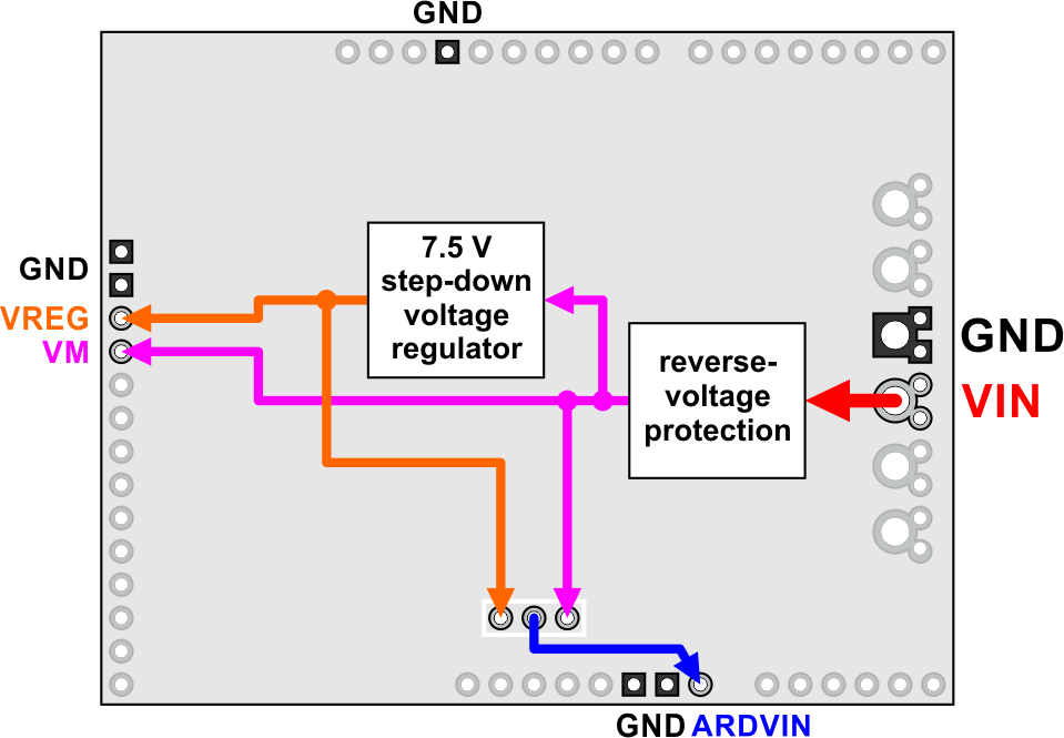 |
Dual G2 high-power motor driver shield power bus diagram. All of the square ground pads are internally connected. |
|---|
An appropriate motor power supply should be connected to the motor driver’s large VIN and GND pads on the right side of the board. The minimum operating voltage for these shields is 6.5 V, and the maximum operating voltage is 30 V for the 18vX versions and 40 V for the 24vX versions. These are absolute maximums, so the 18vX versions are not intended for use with 24 V batteries, which can significantly exceed 24 V when fully charged.
It is important that you use a power source that is capable of delivering the current your motors will require. For example, alkaline cells are typically poor choices for high-current applications, and you should almost never use a 9V battery (the rectangular type with both terminals on the same side) as your motor power supply.
The board includes a reverse-voltage protection circuit that helps prevent damage in case the motor power supply is connected backward. The reverse-protected input voltage can be accessed for use in other circuits through the pin labeled VM on the left side of the board, and this reverse-protected voltage can optionally be used to power an Arduino when this board is used as a shield:
 |
The board also includes a 7.5 V, 1 A switching step-down regulator. The regulator output can be accessed through the pin labeled VREG on the left side of the board, and it can also optionally be used to power an Arduino when this board is used as a shield:
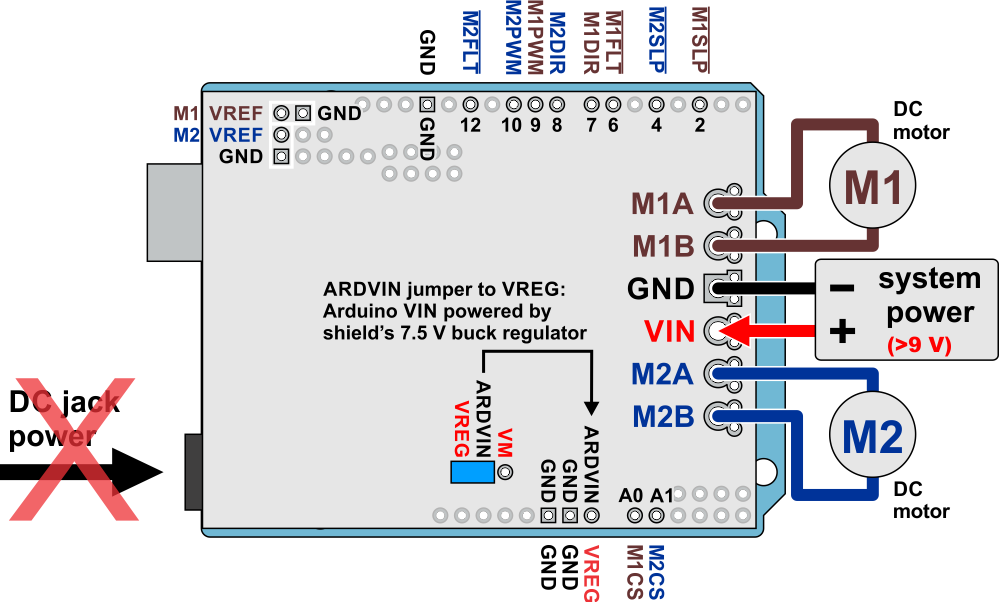 |
This is the recommended method for powering an Arduino for shield input voltages over 9 V.
The blue power LED is connected by VREG and illuminates whenever the board is powered.
Warning: When powering an Arduino from the motor shield, you must never connect a different power supply to the Arduino’s VIN pin or plug a power supply into the Arduino’s power jack, as doing so will create a short between the shield’s power supply and the Arduino’s power supply that could permanently damage both the Arduino and the motor shield.
Note that the shorting block just routes the motor power to the Arduino VIN pin, so plugging in USB with this shorting block in place is just like plugging in USB with the Arduino powered from its power jack. On standard Arduinos we recommend against plugging a powered Arduino into USB (see this forum post for more information), but on some Arduino-compatible boards such as the A-Stars, this is completely safe.
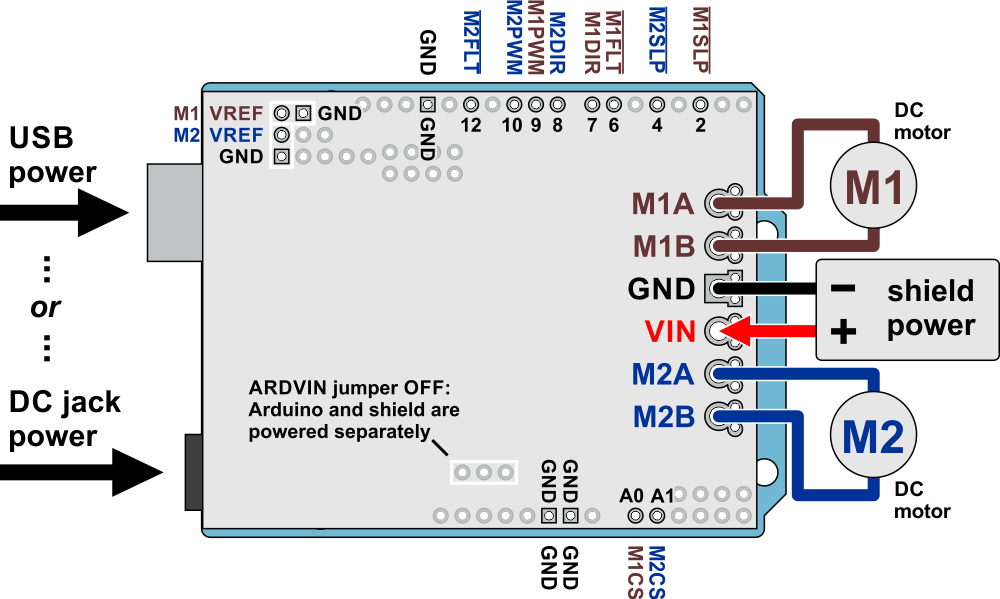
If you leave the ARDVIN jumper off, the Arduino power is independent of the shield power, and the two must be powered separately when using this driver as a shield:
 |
Changing VREG to 5 V
The on-board regulator can optionally be configured to output 5 V instead of 7.5 V by cutting a trace between two SMT jumper pads:
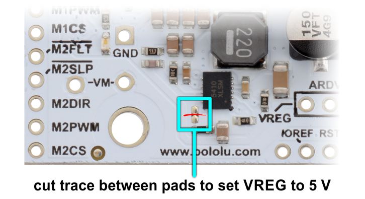 |
You can bridge these two pads with solder if you later want to restore it to 7.5 V. Note that 5 V is too low to power typical Arduinos through their VIN pins (which is why the default is 7.5 V).
Real-world power dissipation consideration
The MOSFETs can handle large current spikes for short durations (e.g. 100 A for a few milliseconds), and the driver’s current chopping will keep the average current under the set limit. The peak ratings are for quick transients (e.g. when a motor is first turned on), and the continuous rating is dependent on various conditions, such as the ambient temperature. PWMing the motor will introduce additional heating proportional to the frequency. The actual current you can deliver will depend on how well you can keep the motor driver cool. The driver’s printed circuit board is designed to draw heat out of the MOSFETs, but performance can be improved by adding a heat sink or air flow. For high-current installations, the motor and power supply wires should also be soldered directly instead of going through the supplied terminal blocks, which are rated for up to 16 A.
Warning: This motor driver has no over-temperature shut-off. An over-temperature or over-current condition can cause permanent damage to the motor driver. You might consider using either the driver’s integrated current sense output or an external current sensor to monitor your current draw.
This product can get hot enough to burn under normal operating conditions. Take care when handling this product and other components connected to it.
4.b. Control and feedback pins
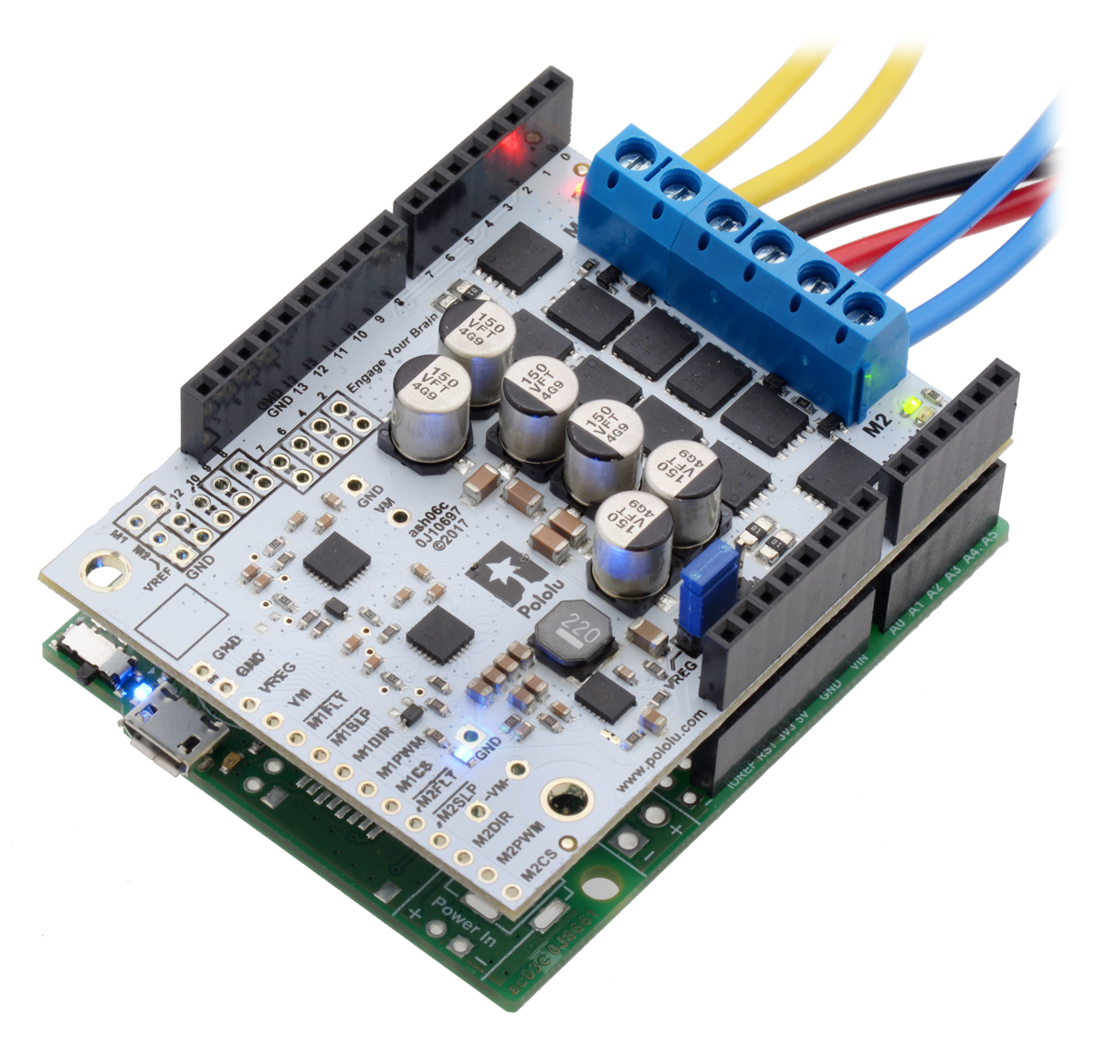
|
Dual G2 high-power motor driver shield powering an Arduino with the shield’s 7.5 V regulator (VREG). |
|---|
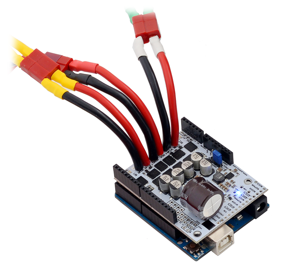
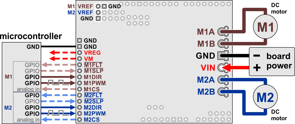 |
Dual G2 high-power motor driver shield connected to a microcontroller (dashed connections are optional). |
|---|
This table explains what the motor driver’s control and feedback pins are and how they connect to an Arduino when the driver is used as a shield:
| Motor driver pin | Default state | Arduino pin |
Description |
|---|---|---|---|
| M1FLT | 6 | Fault indicators: These open-drain outputs drive low when a fault is occurring. In order to use these outputs, they must be pulled up to your system’s logic voltage (such as by enabling the internal pull-ups on the Arduino pins they are connected to). See below for details. | |
| M2FLT | 12 | ||
| M1SLP | HIGH | 2 | Inverted sleep inputs: These pins are pulled high, enabling the driver by default. Driving these pins low puts the motor driver channels into a low-current sleep mode and disables the motor outputs (setting them to high impedance). |
| M2SLP | 4 | ||
| M1DIR | LOW | 7 | Motor direction inputs: When DIR is low, motor current flows from output A to output B; when DIR is high, current flows from B to A. |
| M2DIR | 8 | ||
| M1PWM | LOW | 9 | Motor speed inputs: A PWM (pulse-width modulation) signal on these pins corresponds to a PWM output on the corresponding channel’s motor outputs. When a PWM pin is low, the corresponding motor brakes low (both A and B are shorted together through ground). When it is high, the motor is on. The maximum allowed PWM frequency is 100 kHz. |
| M2PWM | 10 | ||
| M1CS | A0 | Current sense outputs: These pins output voltages proportional to the motor currents when the H-bridges are driving (but not while they are braking, including when current limiting is active). The output voltage is about 10 mV/A for the 18v22 and 20 mV/A for the other versions, plus an approximate offset of 50 mV. | |
| M2CS | A1 | ||
| M1VREF | Current limit threshold adjustments: A resistor can be connected between VREF and the adjacent GND to lower the current limiting (chopping) threshold from its default setting. See below for details. | ||
| M2VREF |
Motor control options
With the PWM pin held low, both motor outputs will be held low (a brake operation). With PWM high, the motor outputs will be driven according to the DIR input. This allows two modes of operation: sign-magnitude, in which the PWM duty cycle controls the speed of the motor and DIR controls the direction, and locked-antiphase, in which a pulse-width-modulated signal is applied to the DIR pin with PWM held high. Our Arduino library for this driver uses sign-magnitude operation.
In locked-antiphase operation, a low duty cycle drives the motor in one direction, and a high duty cycle drives the motor in the other direction; a 50% duty cycle turns the motor off. A successful locked-antiphase implementation depends on the motor inductance and switching frequency smoothing out the current (e.g. making the current zero in the 50% duty cycle case), so a high PWM frequency might be required.
| Inputs | Outputs | Operation | |||
|---|---|---|---|---|---|
| SLP | DIR | PWM | MxA | MxB | |
| 1 | 0 | PWM | PWM (H/L) | L | forward/brake at speed PWM % |
| 1 | 1 | PWM | L | PWM (H/L) | reverse/brake at speed PWM % |
| 1 | X | 0 | L | L | brake low (outputs shorted to ground) |
| 0 | X | X | Z | Z | coast (outputs off) |
PWM frequency
The motor driver supports PWM frequencies as high as 100 kHz, but note that switching losses in the driver will be proportional to the PWM frequency. Typically, around 20 kHz is a good choice for sign-magnitude operation since it is high enough to be ultrasonic, which results in quieter operation.
A pulse on the PWM pin must be high for a minimum duration of approximately 0.5 µs before the outputs turn on for the corresponding duration (any shorter input pulse does not produce a change on the outputs), so low duty cycles become unavailable at high frequencies. For example, at 100 kHz, the pulse period is 10 µs, and the minimum non-zero duty cycle achievable is 0.5/10, or 5%.
Fault conditions
The motor driver can detect several fault states that it reports by driving the FLT pin low; this is an open-drain output that should be pulled up to your system’s logic voltage. The detectable faults include short circuits on the outputs, under-voltage, and over-temperature. All of the faults disable the motor outputs but are not latched, meaning the driver will attempt to resume operation when the fault condition is removed (or after a delay of a few milliseconds in the case of the short circuit fault). The over-temperature fault provides a weak indication of the board being too hot, but it does not directly indicate the temperature of the MOSFETs, which are usually the first components to overheat, so you should not count on this fault to prevent damage from over-temperature conditions.
Current sensing
The current sense output sensitivity depends on the motor driver version: it is approximately 10 mV/A for the 18v22 and 20 mV/A for all other versions. There is an offset of approximately 50 mV, and this can vary some from unit to unit, so we recommend first calibrating the current sense by reading this zero-current offset. Each CS output is only active while the corresponding H-bridge is in drive mode; it is inactive (low) when the channel is in brake mode (slow decay), which happens when the PWM input is low or when current limiting is active. Current will continue to circulate through the motor when the driver begins braking, but the voltage on the CS pin will not accurately reflect the motor current in brake mode. The CS voltage is used internally by the motor driver, so to avoid interfering with the driver’s operation, you should not add a capacitor to this pin or connect a load that draws more than a few mA from it.
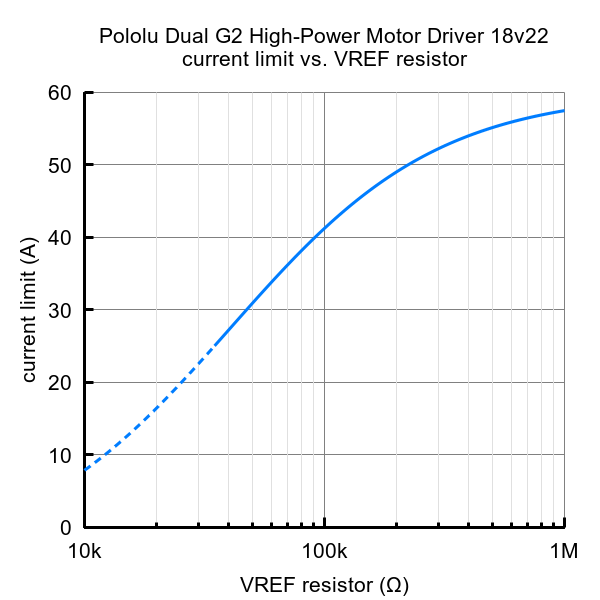
Current limiting
The driver has the ability to limit the motor current through current chopping: once the motor drive current reaches a set threshold, the driver goes into brake mode (slow decay) for about 25 μs before applying power to drive the motor again. This makes it more practical to use the driver with a motor that might only draw a few amps while running but can draw many times that amount (tens of amps) when starting. The default current limiting threshold depends on the version of the motor driver as follows:
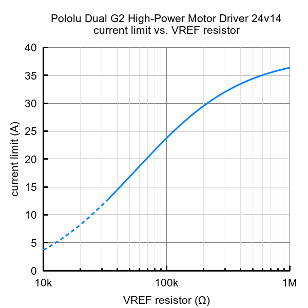
- 40 A for 24v14
- 50 A for 18v18 and 24v18
- 60 A for 18v22
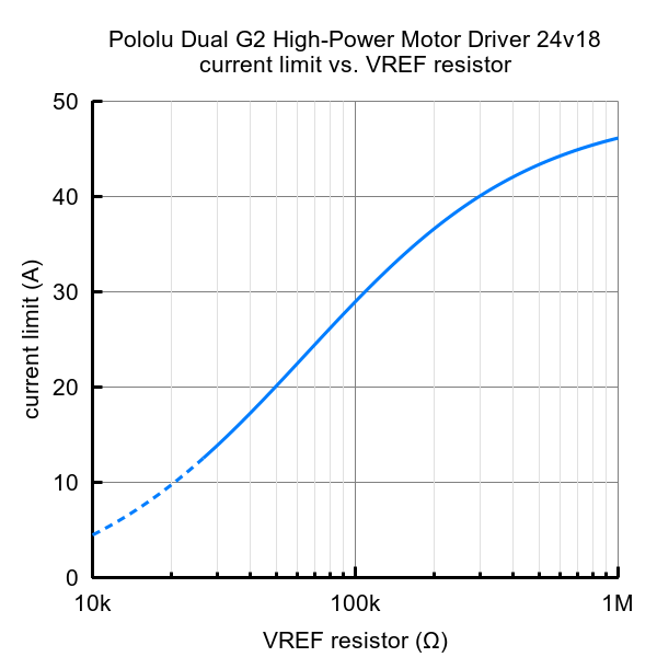
This default threshold can be lowered for each channel by connecting a resistor between the VREF pin and the adjacent GND pin. The graphs below (one for each board version) show how the current limit relates to the VREF resistor value. Note that the current limiting threshold is not highly precise, and is less accurate at especially low settings (indicated by the dashed portion of the curve).
 |
 |
 |
 |
4.c. Remapping the Arduino connections
For some applications, this shield’s default Arduino pin mappings might not be convenient. For example, maybe you want to use the 16-bit Timer 1 for making music on a buzzer and would rather use PWMs from Timer 0 to control your motor speed. Or maybe you don’t care about monitoring the motor current and would rather use all of your analog inputs for reading sensors. With this in mind, we designed the shield to have break points in the connection between the Arduino pins and the motor drivers. It is easy to cut the connections at these points and establish new connections to replace the broken ones if desired.
The connections between the Arduino pins and the motor driver pins are each made through a pair of 0.1″-spaced holes that are connected on the top side of the shield by a thin trace. The following two diagrams show the default pin mapping for motor drivers 1 and 2:
|
|
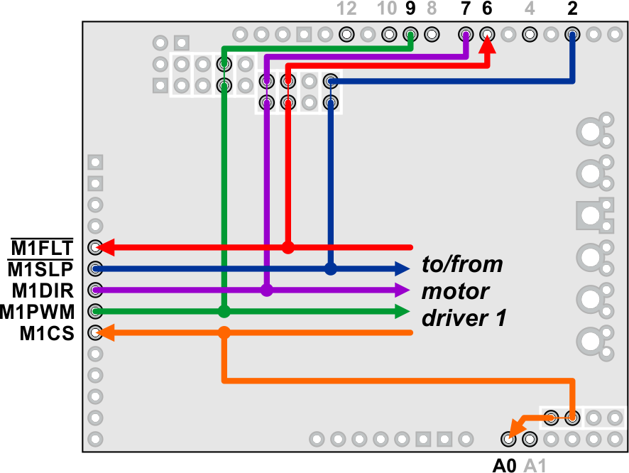
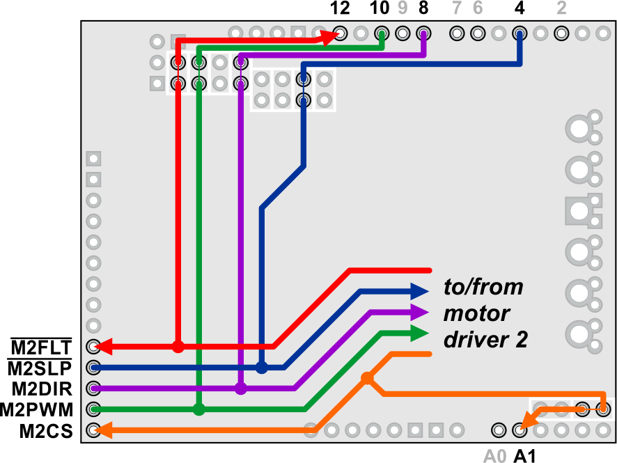
In all cases, the top through-holes of the vertical pairs and the left through-holes of the horizontal pairs connect to the Arduino pin, and the bottom/right through-holes connect to the motor driver pin. To change one of the default mappings, you can use a knife to cut the trace between the appropriate pair of holes on the top side of the PCB (there is no connection to cut on the underside of the PCB) and run a wire from a different Arduino pin to the bottom hole of the pair to create a new connection.
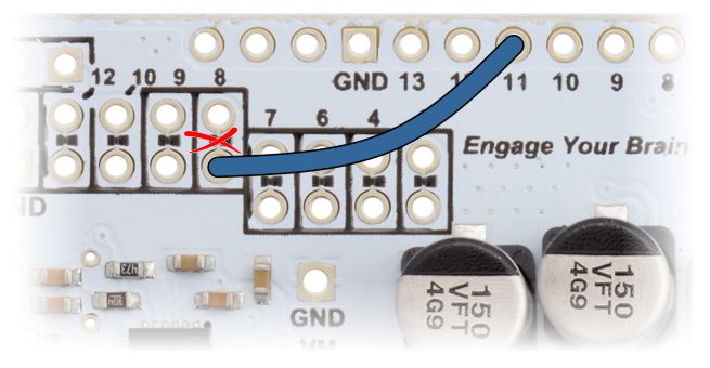 |
Dual G2 high-power motor driver shield remapping example: moving M2DIR from Arduino pin 8 to pin 11. |
|---|
You can later use shorting blocks to restore the default pin mapping if you populate the severed hole pairs with 1×2 pieces of the included 0.1″ male header strip.
5. Programming your Arduino
Our Arduino library for the Dual G2 High-Power Motor Driver Shield makes it easy to get started writing your Arduino sketches. A link to download the library, installation instructions, and the library command reference can be found on the library’s github page. Once installed, we recommend you try out the example sketch by selecting
File > Examples > DualG2HighPowerMotorShield > Demo
from the Arduino IDE, or by copying the following code into a new sketch (and make sure to uncomment the line at the top that corresponds to the version of your motor driver shield):
#include "DualG2HighPowerMotorShield.h"

// Uncomment the version corresponding with the version of your shield.
DualG2HighPowerMotorShield24v14 md;
// DualG2HighPowerMotorShield18v18 md;
// DualG2HighPowerMotorShield24v18 md;
// DualG2HighPowerMotorShield18v22 md;

void stopIfFault()
{
  if (md.getM1Fault())
  {
    md.disableDrivers();
	delay(1);
    Serial.println("M1 fault");
    while (1);
  }
  if (md.getM2Fault())
  {
    md.disableDrivers();
	delay(1);
    Serial.println("M2 fault");
    while (1);
  }
}

void setup()
{
  Serial.begin(115200);
  Serial.println("Dual G2 High Power Motor Shield");
  md.init();
  md.calibrateCurrentOffsets();

  delay(10);

  // Uncomment to flip a motor's direction:
  //md.flipM1(true);
  //md.flipM2(true);
}

void loop()
{
  md.enableDrivers();
  delay(1);  // The drivers require a maximum of 1ms to elapse when brought out of sleep mode.

  for (int i = 0; i <= 400; i++)
  {
    md.setM1Speed(i);
    stopIfFault();
    if (i%200 == 100)
    {
      Serial.print("M1 current: ");
      Serial.println(md.getM1CurrentMilliamps());
	}
    delay(2);
  }

  for (int i = 400; i >= -400; i--)
  {
    md.setM1Speed(i);
    stopIfFault();
    if (i%200 == 100)
    {
      Serial.print("M1 current: ");
      Serial.println(md.getM1CurrentMilliamps());
	}
    delay(2);
  }

  for (int i = -400; i <= 0; i++)
  {
    md.setM1Speed(i);
    stopIfFault();
    if (i%200 == 100)
    {
      Serial.print("M1 current: ");
      Serial.println(md.getM1CurrentMilliamps());
	}
    delay(2);
  }

  for (int i = 0; i <= 400; i++)
  {
    md.setM2Speed(i);
    stopIfFault();
    if (i%200 == 100)
    {
      Serial.print("M2 current: ");
      Serial.println(md.getM2CurrentMilliamps());
    }
    delay(2);
  }

  for (int i = 400; i >= -400; i--)
  {
    md.setM2Speed(i);
    stopIfFault();
    if (i%200 == 100)
    {
      Serial.print("M2 current: ");
      Serial.println(md.getM2CurrentMilliamps());
    }
    delay(2);
  }

  for (int i = -400; i <= 0; i++)
  {
    md.setM2Speed(i);
    stopIfFault();
    if (i%200 == 100)
    {
      Serial.print("M2 current: ");
      Serial.println(md.getM2CurrentMilliamps());
    }
    delay(2);
  }

  md.disableDrivers(); // Put the MOSFET drivers into sleep mode.
  delay(500);

}
This example enables the drivers and ramps motor 1 from stopped to full speed forward, ramps down to full speed reverse, and back to stopped. Then, it does the same with the other motor. After motor 2 is stopped, sleep mode is entered for 500 ms before the demo enables the drivers again. Current readings for each motor are sent over serial and can be seen with the serial monitor. If a fault is detected, a message is sent over serial.
Note: Even if you don’t have any motors yet, you can still try out this sketch and use the motor indicator LEDs for feedback that the shield is working properly.
6. Dimensions
|
|
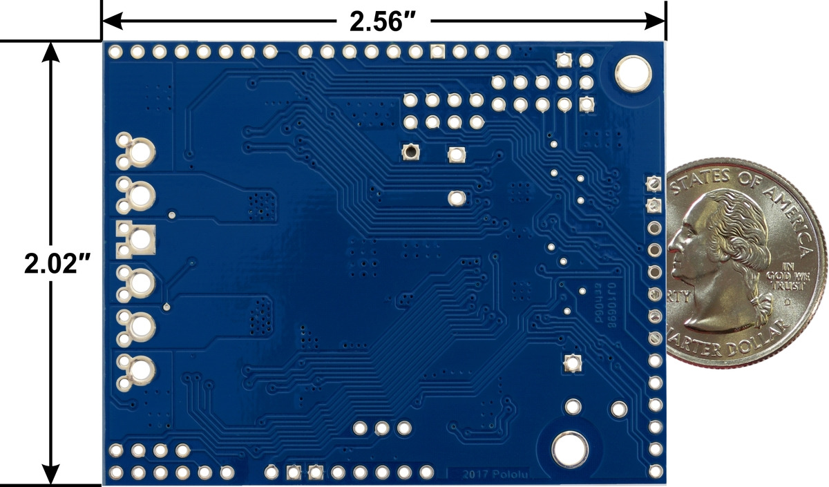
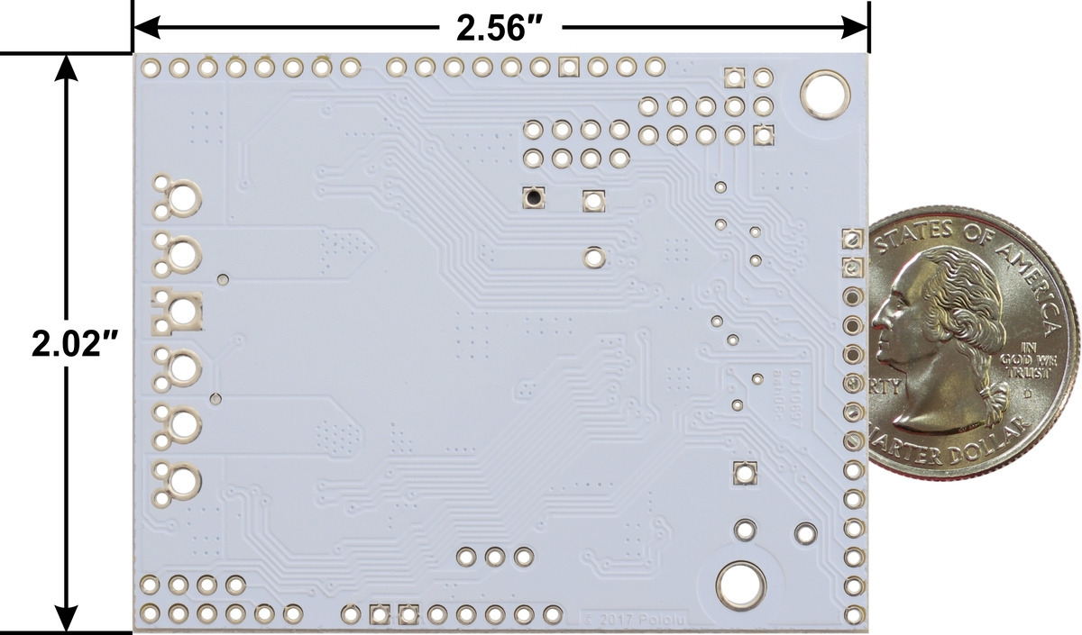
Dimension diagrams for each motor driver are available as PDFs (the overall dimensions are the same for all four versions, but these two pdfs show the differences in components between the blue and white versions):
- 18v18/24v14 dimension diagram (261k pdf)
- 18v22/24v18 dimension diagram (271k pdf)


Home | Forum | Blog | Support | Ordering Information | Lists | Distributors | BIG Order Form | About | Contact
© 2001–2026 Pololu Corporation
