Support » Tic Stepper Motor Controller User’s Guide » 4. Setting up the controller »
4.10. Setting up analog speed control
This section explains how to set up the Tic to read an analog input and use that signal to control the speed of the stepper motor.
If you have not done so already, you should follow the instructions in Section 4.3 to configure and test your stepper motor. Next, with the system unpowered, connect your analog signal to the Tic as described below.
If you are using a potentiometer to make the analog signal, you should connect the potentiometer’s wiper to SDA/AN and connect the other two ends to GND and SCL, as shown in the diagram below. In analog mode, the SCL line is driven high (5 V) to power the potentiometer (note that the SCL pin is protected by a 220 Ω or 470 Ω series resistor, so it will not be damaged by inadvertent shorts to ground).
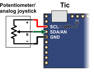 |
If you are using something other than a potentiometer to generate the analog signal, make sure that the ground node of that device is connected to a GND pin on the Tic, and that the analog signal from that device is connected to the Tic’s SDA/AN line. The Tic’s analog input can only accept signals between 0 V and 5 V with respect to GND; signals outside of this range could damage the Tic.
Now connect the Tic to your computer via USB. In the Tic Control Center software, set the Tic’s control mode to “Analog speed” and click “Apply settings”. In the “Scaling” box, click “Learn…” to start the Input Setup Wizard. The wizard will help you measure the neutral, maximum, and minimum positions of your analog signal. When the wizard is finished, it will set five of the input scaling parameters (input maximum, input neutral max, input neutral min, input minimum, and invert input direction) appropriately so that the neutral analog signal gets mapped to a velocity of 0, the maximum analog signal gets mapped to the target maximum, and the minimum analog signal gets mapped to the target minimum. You should change the target maximum to be equal to the maximum velocity that you want your motor to move in the forward/positive direction. Since you already set the “Max speed” parameter in the “Motor” box (see Section 4.3), you could just copy that value into the target maximum box. If you want your motor to go the same speed in both directions, you should set the target minimum to the negative of the target maximum. Otherwise, you should set the target minimum to be the lowest (most negative) velocity that you want your motor to have when moving in the other direction. Click “Apply settings” to save these settings to the Tic.
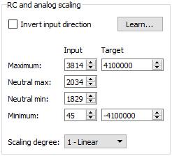 |
Example Tic scaling settings for analog speed control mode. |
|---|
Now connect motor power and click “Resume” to start your system. If the Tic Control Center software says “Motor de-energized because of safe start violation.”, you should center your input. After doing that, you should be able to move your analog input to control the speed of the motor.
The safe-start feature helps prevent unexpected motion of the stepper motor by making sure that the stepper motor does not start moving until after your analog input goes to the neutral position. When you are starting up your system, you will always have to move your input to the neutral position if it was not there already. It is possible to disable this feature by checking the “Disable safe start” checkbox in the “Advanced settings” tab.
You should make sure that the motor is moving in the correct direction. If it is not, you can check the “Invert motor direction” checkbox to fix it. (You could also rewire the stepper motor to reverse the current in one coil, but be sure to turn off the stepper motor power before doing that.)
Finally, check the “Scaling degree” parameter. The default setting is “1 – Linear”. If you want finer control at low speeds and coarser control at high speeds, you can change it to one of the higher settings.
For details about how the input scaling works, see Section 5.2.
Related products


Related categories


Home | Forum | Blog | Support | Ordering Information | Lists | Distributors | BIG Order Form | About | Contact
© 2001–2026 Pololu Corporation
