Support » Tic Stepper Motor Controller User’s Guide » 4. Setting up the controller »
4.11. Setting up encoder position control
This section explains how to set up the Tic to read signals from a quadrature encoder and use them to control the position of the stepper motor.
The Tic does not support closed-loop control with encoder feedback. The Tic’s encoder input is meant to be connected to a rotary encoder that is turned by hand. If you have a stepper motor with an integrated encoder, you should not try to connect the motor’s encoder to the Tic.
If you have not done so already, you should follow the instructions in Section 4.3 to configure and test your stepper motor.
When in encoder mode, the Tic uses its RX and TX lines as encoder inputs. Each of these lines has an integrated 100 kΩ resistor pulling it up to 5 V and a 220 Ω or 470 Ω series resistor protecting it from short circuits (e.g. in case it is inadvertently put into serial mode, which uses TX as an output, with an encoder still connected). The Tic expects to see standard quadrature encoder signals like this on its encoder inputs:
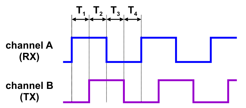 |
The time between the channel transitions (labeled T1-4 in the diagram above) must be at least 100 µs.
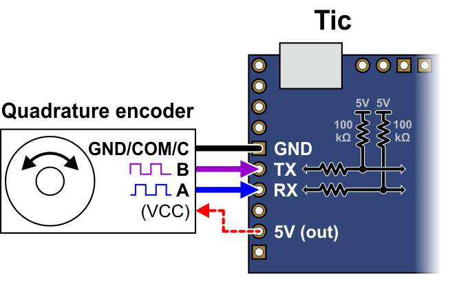
For this control interface, we generally recommend common three-pin mechanical rotary encoders with quadrature outputs, though other kinds of quadrature encoders can also be used. A three-pin rotary encoder has two signal pins, A and B, which should be connected to RX and TX on the Tic, and a common pin (sometimes labeled “C”) that should be connected to ground. Note that the common pin is often in the middle, but you should always refer to your encoder documentation to identify which pin is which. These encoders do not require power as the signal pins just alternate between floating and ground as the dial is rotated. The built-in pull-ups on the RX and TX pins make the signal high during the times when the encoder outputs are floating, so there is no need for external pull-ups. Other kinds of quadrature encoders might require power, and the 5V output on the Tic can be used to power them if their documentation indicates they can operate at 5 V.
As a first step, you should turn off the power to your system and then connect your encoder to the Tic as described above and shown in the diagram below. You can swap your A and B connections to flip the direction of the encoder.
 |
Now connect the Tic to your computer via USB. In the Tic Control Center software, set the Tic’s control mode to “Encoder position”. If you have previously changed the target maximum and target minimum, you should set them back to their default values of 200 and −200, respectively. If you have previously changed the encoder prescaler or postscaler settings, you should change them both back to their default value of 1. Also, make sure that the “Enable unbounded position control” setting for the encoders is unchecked, as it is by default. Click “Apply settings” to save these settings to the Tic.
Now connect motor power to start your system running. As you turn your encoder, you should see your stepper motor moving proportionally: one count from the encoder corresponds to one step from the Tic.
If your motor is not moving as you turn the encoder, you should look at the message at the bottom of the Tic Control Center and also check for errors in Status tab. If there are any errors, you should address them before continuing. If the system is still not working, you should look at the “Encoder position” displayed in the Status tab, which is the raw count from your encoder. This number is pinned to zero when motor power is off, so make sure you have connected your motor power to the Tic. If you turn your encoder one way, this number should go up. If you turn it the other way, this number should go down. If the “Encoder position” is not changing, or only changing by one count, it is possible that your encoder is not wired correctly. Check all of your connections and soldering joints (if applicable). If you have access to an oscilloscope, you should check the signals on RX and TX. If the “Encoder position” is responding properly to the encoder but the “Input after scaling” variable is not, then make sure you have set those settings to their defaults as described above.
The Tic expects that transitions on its encoder inputs will be at least 100 µs apart. If your encoder signal is faster than this, the Tic might miss some encoder counts or could even measure counts in the wrong direction. To see whether this is happening, you should try turning your encoder as fast as you expect it to be turned in your application. As you do this, look at the “Encoder skip” count shown in the “Errors” box in the “Status” tab. If the count goes up when you turn the encoder, that means the Tic is missing some encoder counts. In that case, if encoder accuracy is important in your application, you might consider getting a different encoder or turning your encoder more slowly.
You should make sure that the motor is moving in the correct direction. If it is not, you can swap the RX and TX connections or check the “Invert motor direction” checkbox to fix it. (You could also rewire the stepper motor to reverse the current in one coil, but be sure to turn off the stepper motor power before doing that.)
Next, you should use the encoder prescaler and postscaler to specify how far the stepper motor should move when you turn the encoder. Every time the encoder position changes by the prescaler amount, the “Input after scaling” variable will be changed by the postscaler amount. So if you increase the prescaler from its default value of 1, it will take more encoder movement to get the same amount of movement from the stepper motor. If you increase the postscaler from its default value of 1, the stepper motor will move further for the same amount of movement from the encoder. If your encoder has detents, it usually makes sense to set the encoder prescaler to the number of counts you get per detent, which is typically 4.
Finally, you should set the target maximum and minimum parameters in the “Scaling” box to set the range of motion of your system. The target maximum must be zero or more, and the target minimum must zero or less. These numbers are denominated in microsteps if you have enabled microstepping. Note that these are the only two numbers in the “Scaling” box that have an effect in encoder mode. Alternatively, if you want your system’s range to be unlimited, check the “Enable unbounded position control” checkbox, in which case all the numbers in the “Scaling” box will be ignored.
For details about how the Tic’s encoder input works, see Section 5.3.
Related products


Related categories


Home | Forum | Blog | Support | Ordering Information | Lists | Distributors | BIG Order Form | About | Contact
© 2001–2026 Pololu Corporation
