Support » Pololu Zumo Shield for Arduino User’s Guide » 3. The Zumo Shield in detail »
3.a. Features and components
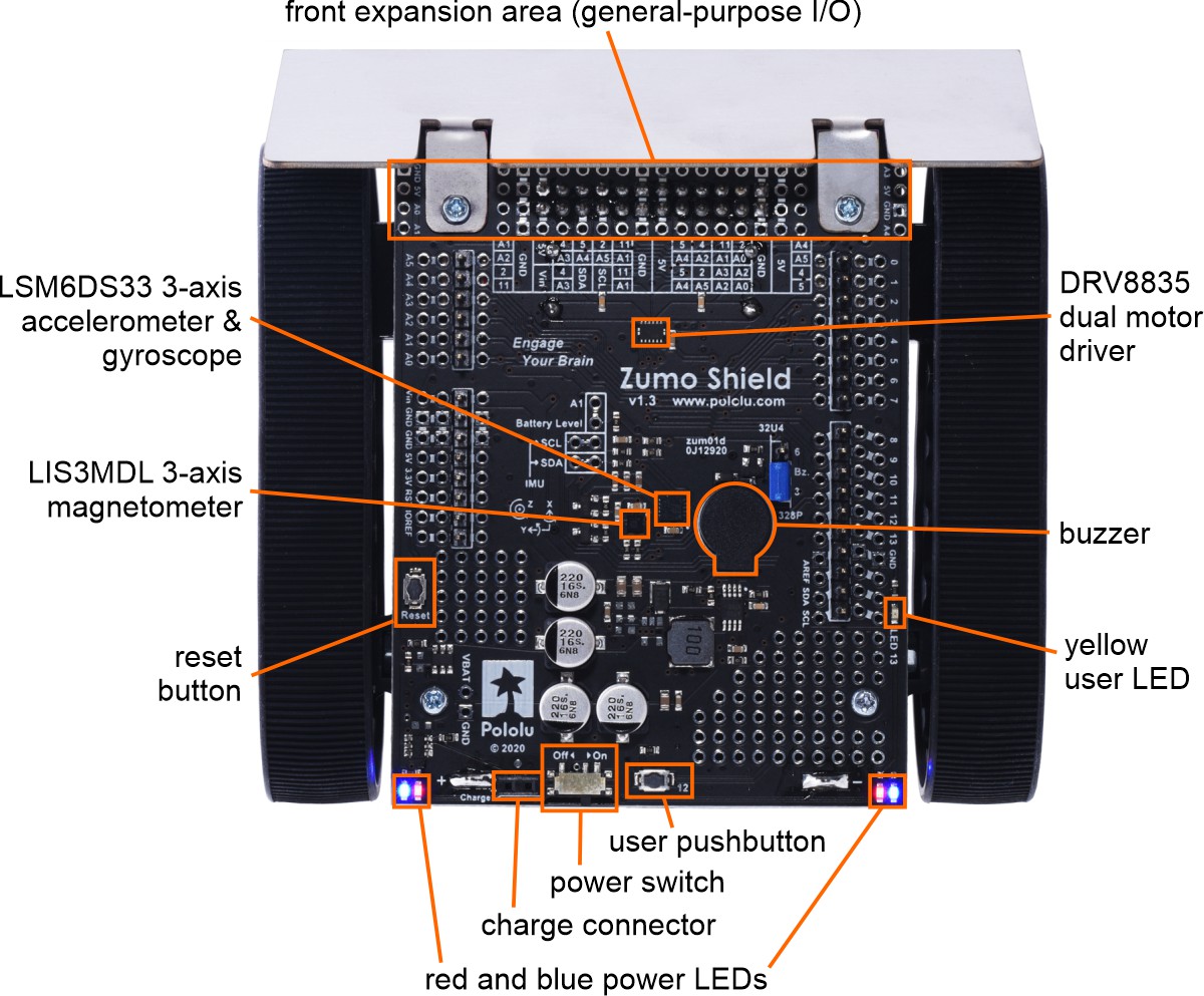
The main features of the Zumo Shield (v1.3) are labeled in this diagram:
 |
Power
The Zumo chassis has an internal compartment for four AA batteries. We recommend using rechargeable AA NiMH cells, which results in a nominal voltage of 4.8 V (1.2 V per cell). You can also use alkaline cells, which would nominally give you 6V.
A direct connection to the battery terminals is provided by the battery charger connector on the rear edge of the shield, which can be used to recharge the Zumo’s batteries without removing them from the chassis. The positive pin of the charge connector, on the left, is indicated by a plus sign (+). A charger like the iMAX-B6AC, connected by clipping its alligator clips to a pair of jumper wires inserted into the charge connector, works well for charging the Zumo.
After passing through reverse protection, the battery voltage is connected to the rest of the shield by the power switch. The switched battery voltage is designated VBAT and provides power to the motors through the DRV8835 motor driver. An on-board boost regulator, also supplied from VBAT, generates 7.45 V to power the Arduino through its Vin pin. In turn, the Arduino’s regulated 5V and 3.3V voltages supply power to the motor driver logic, buzzer circuit, and compass module on the Zumo Shield.
Warning: When powering the Arduino from the Zumo Shield, you must never connect a different power supply to the Arduino’s VIN pin or plug a power supply into the Arduino’s power jack, as doing so will create a short between the shield’s power supply and the Arduino’s power supply that could permanently damage both the Arduino and the Zumo Shield.
When the Arduino is connected to a computer via USB, it will receive power (and supply 5V and 3.3V to the shield) even when the Zumo Shield’s power switch is off. This can be useful if you want to test your Arduino program without allowing the motors to run, since turning the power switch off disconnects motor power (VBAT).
LEDs
There are five LEDs on the Zumo Shield:
- A set of power LEDs, one blue and one red, is located in each of the two rear corners of the shield.
- A yellow user LED is located on the right edge of the shield. It is connected to digital pin 13 on the Arduino, in parallel with the Arduino’s onboard user LED.
Pushbuttons
Two pushbuttons can be soldered to the Zumo Shield:
- The reset pushbutton is located on the left edge of the shield. It is connected to the Arduino’s RESET pin and can be pressed to reset the Arduino.
- The user pushbutton is located on the rear edge of the shield. It is connected to digital pin 12 on the Arduino; pressing the button pulls the pin low, and we recommend enabling the Arduino’s internal pull-up to pull the pin high otherwise. The Pushbutton part of our Zumo Shield Arduino library, makes it easy to detect and debounce button presses with this pushbutton.
Motor driver
An integrated DRV8835 dual motor driver on the Zumo Shield drives the Zumo’s two micro metal gearmotors. Four Arduino pins are used to control the driver:
- Digital pin 7 controls the right motor direction (LOW drives the motor forward, HIGH drives it in reverse).
- Digital pin 8 controls the left motor direction.
- Digital pin 9 controls the right motor speed with PWM (pulse width modulation).
- Digital pin 10 controls the left motor speed with PWM.
The ZumoMotors object in the Zumo Shield Arduino library provides functions that allow you to easily control the motors, and it can optionally take care of flipping a direction signal for you if you accidentally soldered in a motor backwards.
Buzzer
The Zumo Shield comes with a buzzer that can be used to generate simple sounds and music (for example, you could use it to produce an audible countdown at the beginning of a sumo match). The buzzer control line is labeled BZ on the shield; if you alternate between driving it high and low at a given frequency, the buzzer will produce sound at that frequency.
The ZumoBuzzer object in the Zumo Shield Arduino library uses hardware PWM to play notes on the buzzer, with digital pin 3 (OC2B) on an Arduino Uno or an older Arduino, or with digital pin 6 (OC4D) on an Arduino Leonardo or A-Star 32U4 Prime. A jumper is provided to connect the BZ input to the appropriate Arduino output, as detailed in Section 3.c.
Front expansion area
A number of I/O, power, and ground connections are brought to the front of the Zumo Shield to allow the mounting of additional sensors and other components. The pinout of this front expansion area is detailed in Section 3.b.
Inertial sensors
The Zumo Shield includes on-board inertial sensors, which can be used to sense acceleration and orientation for advanced applications:
- The v1.3 Zumo Shield features an LSM6DS33 3-axis accelerometer and gyroscope and an LIS3MDL 3-axis magnetometer.
- The v1.2 Zumo Shield features an LSM303D 3-axis accelerometer and magnetometer and an L3GD20H 3-axis gyroscope.
- The original Zumo Shield features an LSM303DLHC 3-axis accelerometer and magnetometer.
The inertial sensors are detailed in Section 3.d.


Home | Forum | Blog | Support | Ordering Information | Lists | Distributors | BIG Order Form | About | Contact
© 2001–2026 Pololu Corporation
