Pololu Blog »
New products: G2 High-Power Motor Driver 18v25 and 24v21 (and price drops for other G2 drivers)
 |
Our second-generation family of high-power motor drivers continues to grow with the release of our G2 High-Power Motor Driver 18v25 and G2 High-Power Motor Driver 24v21, discrete MOSFET H-bridges that can supply a brushed DC motor with up to 25 A of continuous current at up to 30 V or up to 21 A of current at up to 40 V, respectively. In addition, we’ve lowered the prices of the 18v17 and 24v13 versions to make them even more affordable.
 |
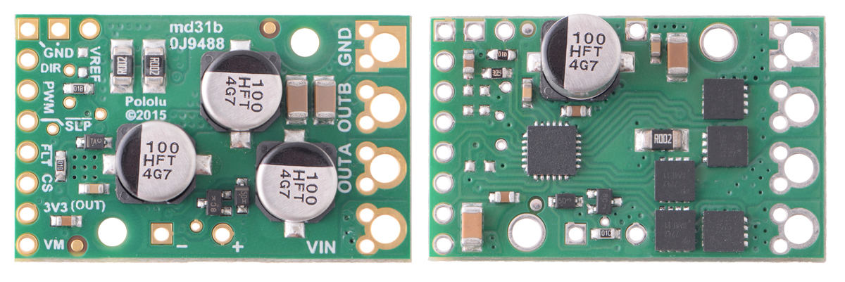
The new G2 18v25 and G2 24v21 drivers’ double-sided design allows them to retain the same board dimensions as their 18v17 and 24v13 siblings, even though they can deliver significantly more power. The G2 drivers are half an inch shorter and can handle the same (or slightly more) current compared to the original 18v25 and 24v20 they are designed to replace, and they are less than half the size of the original 18v25 CS and 24v23 CS while offering basic current sensing functionality that can eliminate the need for a dedicated current sensor in some applications. As with previous G2 drivers, they also include reverse-voltage protection and a current limiting feature.
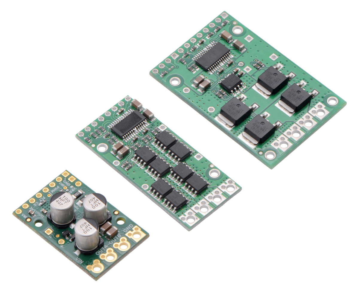 |
Pololu G2 High-Power Motor Driver 24v21 next to original high-power motor driver 24v20 and 24v23 CS. |
|---|
 |
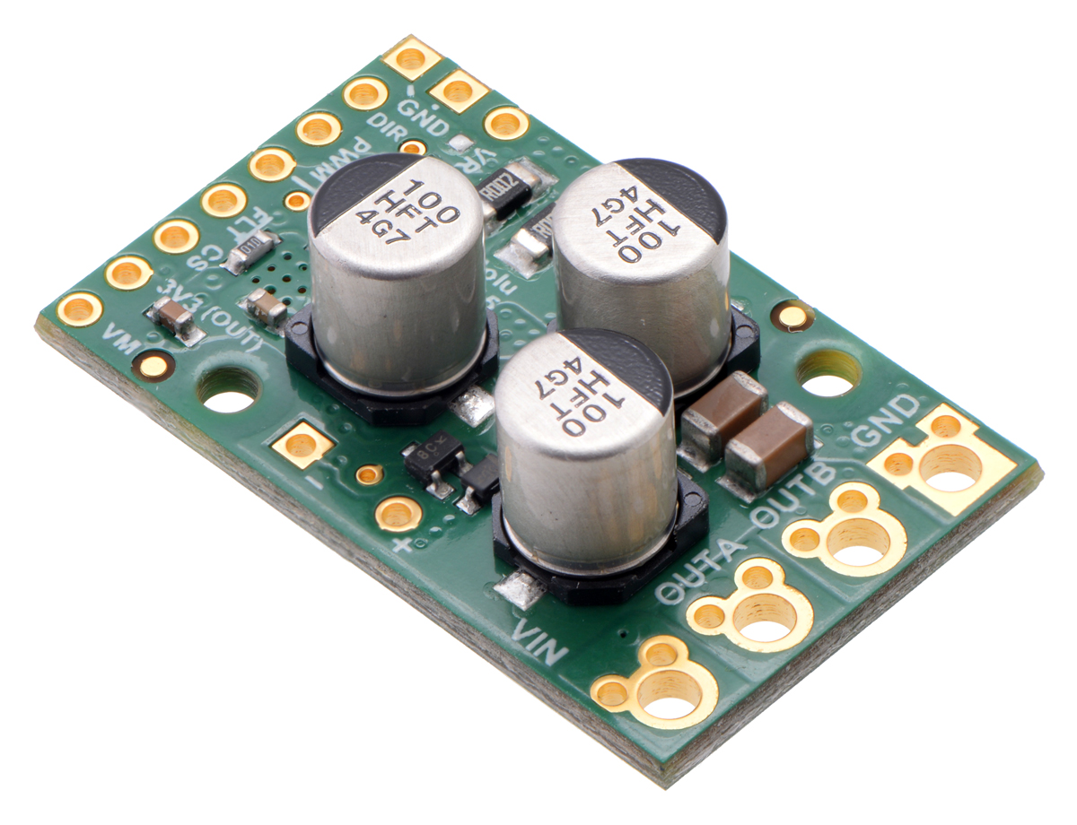
Pololu G2 High-Power Motor Drivers |
|---|
For more information about the G2 motor drivers, see their product pages at the links below.
Related products


-
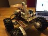
Room mapping robot based on the Rover 5 chassis
- 19 February 2016This robot, created by theophil on Let’s Make Robots, uses a Rover 5 chassis with encoders, a MinIMU, sonar sensors, and a few expansion plates to...
-
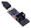
New product: Pololu USB AVR Programmer v2
- 4 March 2016I am excited to announce the release of the Pololu USB AVR Programmer v2, a programmer for the popular AVR microcontrollers from Atmel. Here at...
23 comments


We do not commit to or disclose the components used on our G2 high-power motor drivers.
-Claire

We do not commit to the exact MOSFETs on these, but the Rds(on) is around 1 mohm for the 18v25 and 2.4 mohms for the 24v21. Keep in mind that there are 3 MOSFETs in the current path because of the reverse protection MOSFET.
-Claire

In our tests the G2 High-Power Motor Driver 24v21 was able to handle 21A continuously. Those tests were done in open air at room temperature, so you might see a decrease in performance if your driver is enclosed or in a hot environment. We do not expect varied input voltages to have a significant impact on the continuous current the driver can handle. We did not test the driver with heatsinks, but adding a heatsink would probably slightly improve the amount of current it can handle.
-Claire

Can this be controlled using an Arduino? If so, would it just be the GND, PWM and DIR pins that are needed to control it?

Those G2 motor drivers will work fine with Arduino controllers, and the pins you mentioned are the minimum required connections to the Arduino. You can see more about the functions of each pin on the driver in the truth table in the "Motor control options" sections of those driver's product pages in the links above.
-Derrill

Does this mean that you put capacitors in OUTA - GND and OUTB - GND respectively?
The motor supply pin is labeled VIN, so you should put the capacitor across VIN and GND.
-Derrill

Sorry, I have another question.
There is a + - terminal on this base and it is for the power supply capacitor, is the above capacitor different from it?
-Derrill

-Derrill

I would like to implement regenerative braking using the pololuG2 24v 21 motor driver. Could you let me know if the motor driver supports such operation. Incase it does, could you please point to me to a resource that shows how it can be done using one of these drivers.

Real regenerative braking, where you get a meaningful amount of energy out of a motor that is slowing down, is very difficult and generally not practical. The G2 high power motor drivers are not good candidates for doing this because you do not have sufficient independent control of the different MOSFETs in the H-bridge.
The older (G1) 36v20 CS motor driver does allow variable (PWM) braking, which is part of what you would use to implement regenerative braking, so in that sense it is the best candidate out of our products. We do not know of a good resource to recommend for how to actually implement regenerative braking.
-Tony

Let assume that I define a PWM signal that behaves like a harminic function, in order to have my motor that continue to "vibrate" with angular sinusoidal motion arount the rest position (back and forth with a small angular amplitude).
The point is the follow. I would like to create a current control using the current measured by the board (in particular using the CS pin).
Does the CS pin provides instantaneous or average or RMS current flowing through the board?
If the CS signal is a instantaneous signal, what is its bandwidth in the frequency domain (i.e. the cutoff frequency like few kHz)?

The CS pin does provide an instantaneous measurement of the motor current when the H-bridge is driving, but we do not have specifications for the bandwidth of the signal.
Also, I am not sure if the CS pin's measurements are appropriate for what you are trying to do, so you might consider using an in-line current sensor instead. You can view our selection of current sensors here:
https://www.pololu.com/category/118/current-sensors
- Patrick

As shown in the table in the Pinout section of each driver's product page, both the DIR and PWM pins are internally pulled low.
-Claire

On the website it said "the output voltage is about 20 mV/A plus a 50 mV offset.".
But what is a maximum/minimum of the Vout from the CS pin? I connect 24V to Vin on the board.
I use Mbed's MCU. An analog signal will be read as 0 to 1.
I have to convert it to mV unit, then use the ratio above to calculate the current in Amp unit.
Thank in advance,

The practical voltage range of that pin will depend on your setup, as implied by the sensitivity information you mentioned. When there is no current draw, the CS pin should read ~50mV (the offset). The maximum voltage on the CS pin depends on your particular motor. For example, if the stall current of your motor is 20A, the CS pin would be 450mV when that is reached (i.e. 20A × 20mV/A + 50mV).
Brandon

Post a comment


Home | Forum | Blog | Support | Ordering Information | Lists | Distributors | BIG Order Form | About | Contact
© 2001–2026 Pololu Corporation
