Pololu Blog »
Nathan's line following robot: Suckbot
 |
After branching off into maze solving, pushing into sumo, and finding our way through dead reckoning, we circled back and had another line following competition at LVBots. I started designing the Suckbot before the previous line following competition over a year before this one, but the design dragged on and there was no urgent push to get it finished without another competition. The robot is designed to suck itself down to the course so it can go faster. I was able to get it following lines and sucking, and I managed to post some middle-of-the-pack lap times, but there was some unexpected behavior when tuning the PID parameters just before the competition, and I think there’s quite a bit of room for improving the robot’s performance in the future.
Concept
During some of the previous line following contests several of the robots had a tendency to slide around the corners. There is an infamous F1 race car (the Brabham BT46B) that featured a large fan that extracted air from the underside of the car, creating a large downforce on the chassis which greatly increased the traction of the tires. The car was remarkably successful, though it had the side effect of exposing drivers to very high lateral acceleration. The design was quickly outlawed after a single race when competitors immediately started work on similar designs. Since there are no structurally weak primates to worry about in the cockpit of a line following robot, it seemed like it would be fun to create one that used the same principles. Thus, the idea for the Suckbot was born.
Chassis design
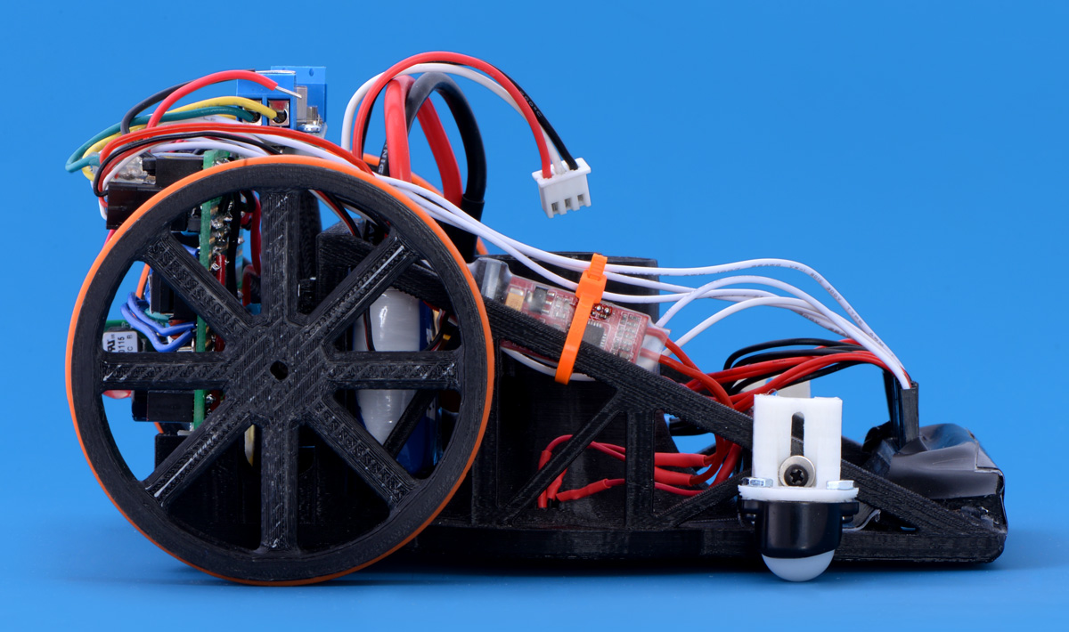 |
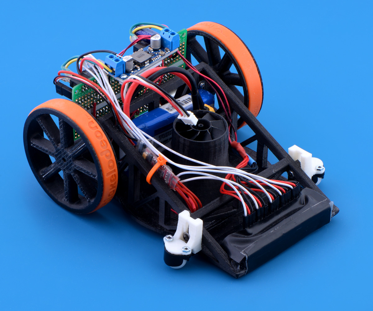
Suckbot side profile. |
|---|
The chassis for the Suckbot is a wedge with centrally located fan that extracts air from a large cavity on the bottom of the robot. This bottom cavity covers several square inches of the surface it is sitting on, so even a fraction of a PSI drop in the static pressure in this pocket of air relative to the atmosphere outside it will create a large force normal to the surface (downforce). The front ball casters and rear drive wheels are mounted using slots to allow the air-gap between the robot and the surface it travels on to be tuned so that enough air can pass through to avoid stalling the fan without requiring a large volume of air movement to create the static pressure difference.
The line-sensors and a pair of ball casters are located at the front of the wedge and the drive wheels are located at the back. The electronics, battery, and drive motors are located between the drive wheels to move as much weight as possible close to the turning axis of the robot, which reduces its angular momentum and allows for quick turns.
The bottom of the robot is a continuous surface so that the pocket of low pressure air can be formed underneath, but the top sides of the wedge are trussed to provide a high strength for their weight. The bottom surface and truss beams are relatively thick (about 5 mm), but the 3D printing process used to manufacture the chassis creates a thin shell of solid material on the outside surfaces filled with a thin walled hexagonal honeycomb matrix on the inside, further saving weight.
The fan housing contains several ribs that primarily serve to hold the motor, but were included also in the hope that they would create a sort of vane-axial fan system to improve the static pressure developed by the fan.
The chassis was designed using SolidWorks and printed with ABS plastic on a modified FlashForge Creator 3D printer at SYN Shop (a local hackerspace). I don’t remember the exact print-time for the chassis, but it was something like 8 to 11 hours.
Mechanical systems
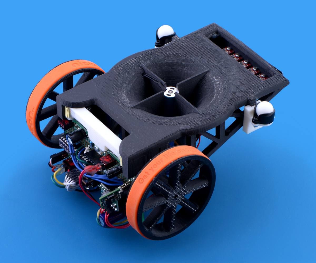 |
Suckbot bottom. |
|---|
The suction fan uses a 30 mm, 8 blade rotor designed for ducted fans on RC airplanes. A brushless DC motor that is rated to run at 4500 rpm/volt is used to drive the fan, so it runs at about 30,000 RPM at the battery voltage. It would be really cool if the robot could also run on an inverted surface, but the Suckbot tips the scale at right about 300 g with the battery (75 g) and the largest load I’ve been able to lift with the suction is only about 140 g.
The two drive motors are Pololu high-power micro metal gearmotors with a 30:1 gear ratio. I decided on the gear ratio based on what was used on other robots in previous line following competitions. I designed a set of 70 mm main drive wheels to use some silicone wristbands as tires. The wheels are secured to the D-shaped output shafts on the motors using a captive nut and set screw. They were 3D printed using ABS plastic on the same printer as the chassis. I experimented with some Pololu 70×8mm wheels in my testing. The injection-molded Pololu wheels ran smoother, but the wider silicone wrist band tires had more traction and I liked having orange tires, so I stuck with them.
I also made and 3D printed some ball casters for the front, but when I turned on the fan suction, they didn’t roll very well and the robot moved much slower. I designed some mounts for a pair of Pololu 1/2″ plastic ball casters, which worked much better.
As I mentioned previously, the wheels and casters are mounted using slots that allow the ride height to be adjusted to fine tune the air gap under the robot. The final air gap used for the competition was about 1.3 mm, though I may try to lower this further. The mounts I designed to use the Pololu ball casters don’t allow me to go quite as low as my previous design.
Electrical systems
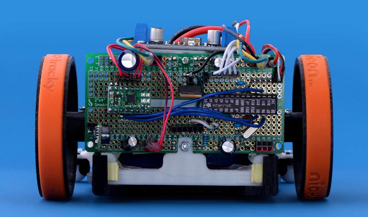 |
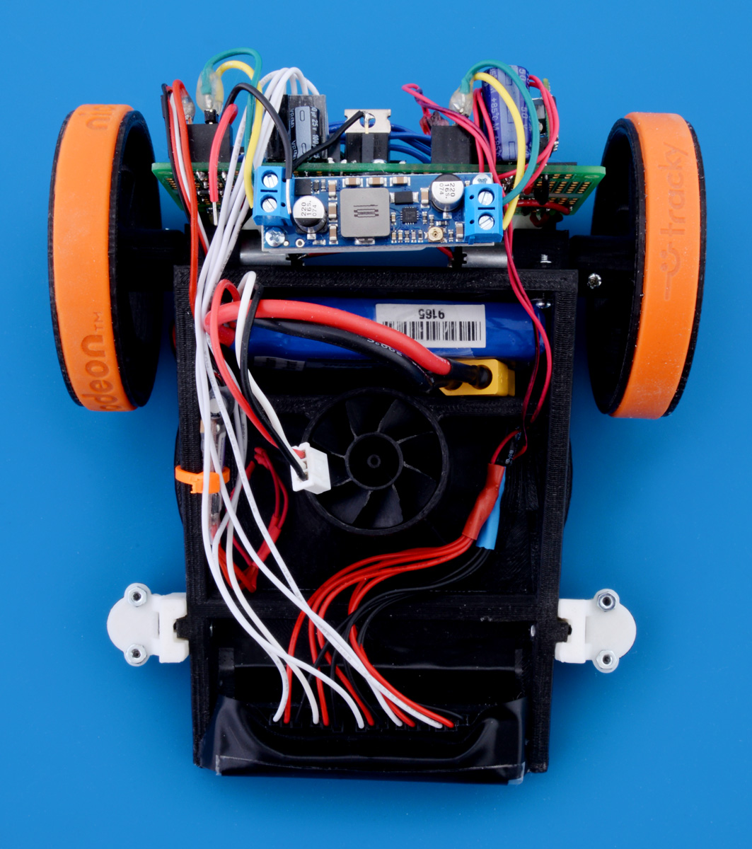
Suckbot back and control board. |
|---|
The microcontoller that runs the Suckbot is an ATmega328P using an Arduino Uno bootloader. There is a tutorial on the Arduino website that shows how to set up this chip on a solderless breadboard in a manner where it behaves like a standard Arduino Uno and Adafruit sells some handy stickers that can be placed directly on the AVR chip to indicate the Arduino pin mappings. The Suckbot initially used a 400-point solderless breadboard to hold most of the electronics, but a few days before the competition I switched over to a SmokingCircuits.com ProtoBoard (similar to Adafruit Perma-Proto Boards) that I got out of the vending machine at SYNShop.
To sense the line, the Suckbot uses an array of 6 Pololu QTR-1RC reflectance sensors mounted about 12 mm above the surface at the front of the robot. I made an add-on bracket for the chassis that allows the spacing between the sensors in the array to be adjusted. This bracket combined with the low ride height also shields the sensors from interference by ambient light.
The drive motors are controlled with a Pololu DRV8833 dual motor driver carrier. It is useful for fast line following to run the motor driver off a regulated power supply to ensure that the mechanical power produced by the motors from a given duty cycle doesn’t vary as the battery voltage changes, so a a Pololu adjustable step-up voltage regulator that is set to 8 V was used power the motor driver from the battery.
The fan motor is controlled by a Turnigy Plush 6A brushless speed controller. I had a lot of trouble getting this to work with my microcontroller and the servo signaling in the Arduino environment. I ended up using an N-Channel MOSFET as a switch across the ground of the ESC so that power to the ESC could be controlled by code on the microcontroller. I’ve detailed the problems I was having and included some demo code that works with my ESC at the end of this post in the hope that anyone else who is using an ESC like this and runs into a similar problem might find it useful.
The battery I used for the competition is a 1,300 mAh 2 cell series LiPo, though I have a smaller 500 mAh battery I used during some of the testing. There is a 5 V regulator on the control board that powers the microcontroller and sensors and the fan motor ESC is powered by the unregulated battery voltage.
Control algorithm
The Suckbot uses a simple PD loop (no I term) that controls the direction the robot is turning by controlling the power to the left and right drive motors. Feedback for the motors is provided from the QTR sensors at the front of the robot. The fan is turned on to a fixed speed a fraction of a second before the robot starts moving. I considered varying the fan power using the PD term since downforce is most helpful when the robot is changing its orientation, but I was concerned the throttle response wouldn’t be quick enough and that the torque from changing the fan speed would affect the robot’s stability.
The robot’s code contains parameters to set minimum and maximum drive motor speeds. The minimum speed I used in my final tuning is a reverse speed, which allows the Suckbot to make sharper turns. However, I had to be careful not to make the reverse speed too large; otherwise, the overall speed would be unnecessarily slowed when the robot oscillated on a line. In my final tuning, I used 800 as a minimum speed and 1400 as a maximum speed where 0 is full reverse, 1000 is stop, and 2000 is full forward.
 |
Suckbot top view. |
|---|
Results
The Suckbot finished in the middle of the pack in the line following competition with a best 3-lap time of 31.8 seconds (about 0.93 m/s average speed). This wasn’t a bad showing for my first line following robot, but I was a bit disappointed because I ran into some problems in my code in the final tuning (integer overflows, I suspect) and had to use slower motor speeds during the contest to ensure the Suckbot would consistently finish the course. Even with the slower code, on one of the two line following courses in the competition there was a corner that consistently caused the robot to veer left off of the course when starting a right hand turn. This occurred despite otherwise following the course very smoothly. The robot used a low fan speed for the competition and I suspect it would have run just as well without it at those drive speeds.
Future plans
I feel like there is a lot of room for improvement in the Suckbot that can be realized by further tuning of the existing platform to take advantage of the additional traction from the fan suction. The existing code needs to be examined and modified to ensure there are no integer overflows. I recently started playing around with an ESP8266 WiFi-to-TTL Serial board, and I plan to use it with a Sharp digital distance sensor (and static position flags around the course) to get wireless telemetry data from the robot so I can tune it using my laptop as it runs the course.
Fan ESC initialization code
When I powered the Arduino and my Turnigy Plush 6A ESC at the same time and initialized the Arduino Servo library to control the ESC with the default timings (“Servo myservo;”) and then set the servo position to 0 (“myservo.write(0);”), the ESC beeped back an error code that indicated an invalid input signal. I experimented with sweeps to different servo positions in my code after the servo library was initialized, but that didn’t seem to work either. I wondered if the ESC was booting, looking for a signal, and throwing an error code while the Arduino was running through its initialization, so I added the N-Channel MOSFET as a switch across the ground of the ESC so I could switch it on and off in my software to be certain that the Arduino was sending a PWM signal to the ESC when it turned on. However, that alone did not fix the problem, and I also had to find a lower threshold for the initial servo position that the ESC recognized as valid.
I’ve included some code below which I used to successfully initialize and control my particular ESC using the Arduino environment and also includes some comments that indicate what the threshold values were for my particular ESC. I noticed in my research that there are versions of this controller that use slightly different microcontrollers than the one I got, so it seems like there are no guarantees that the firmware and the threshold values I found will be the same on your ESC. Hopefully this code will be helpful for you to use as a starting point to find your own threshold values.
#include <Servo.h>
Servo myservo;
const int pinFanPWM = 9;            //I/O pin for the fan ESC servo signal
const int pinFanSwitch = 4;         //I/O pin for the MOSFET turning on the fan ESC

void setup() {
  pinMode(pinFanPWM, OUTPUT);
  pinMode(pinFanSwitch, OUTPUT);

  digitalWrite(pinFanPWM, LOW);
  digitalWrite(pinFanSwitch, LOW);


  //Initialize the fan
  myservo.attach(pinFanPWM);
  myservo.write(10);                //8 is the lowest threshold for the ESC to recognize a valid signal
                                    //during initialization. The top is around 65.
  delay(100);
  digitalWrite(pinFanSwitch,HIGH);  //Turn fan ESC on via MOSFET
  delay(4100);                      //4000 or 4100ms for ESC to initialize
  myservo.write(74);                //71 is the lowest threshold to make the fan turn on
  delay(500);
  myservo.write(10);                //Stop the fan

  //Controller is now initialized. The fan can now be turned on
  delay(2000);
  myservo.write(100);               //Turn fan on medium power
  delay(5000);
  myservo.write(180);               //Turn fan on full power (The ESC recognized anything
                                    //above about 135 as full power)
  delay(5000);
  myservo.write(30);                //Turn fan off again
  delay(2000);
  digitalWrite(pinFanSwitch,LOW);   //Turn fan ESC off via MOSFET (This is not necessary and it will need
                                    //to be reinitiallized to use the fan again.)
}

void loop() {

}
Related products


-

Memorial Day weekend sale
- 22 May 2015We are having a big Memorial Day sale now through Monday, with discounts on over 600 products when you use the coupon code MEMORIALDAY15. Stock up...
-
Grant's line following robot: Pinto
- 27 May 2015My entry for the LVBots line following competition last month was a rehash of my line following robot from last year, Pinto. Unfortunately, my...
11 comments


I used the larger battery for the contest because I was doing testing with it and adjusting parameters just before the contest started and I did not want to throw the robot off by changing to the smaller battery at the last minute. I did not extensively characterize the battery life, but the 500mAh battery was enough for at least a few 10's of laps.
There is a short clip of the robot running in the video for the competition at 2:33. Thanks for asking about it.
Nathan

I haven't published the files anywhere because they are kind of specific to the parts I used (like the fan blades and motor), there are some bugs in the design (like the front sensor mount being taped on) and in general, it doesn't seem like it is easy to modify STL files. Is there some easy way to work with STL files I'm unaware of?
-Nathan
I edit STL files with Tinkercad (www.tinkercad.com). I'ts a very easy tool for creating and editing 3D models. It's capable of importing STL files to edit.
Maybe you already knew that tool, I kinda mastered it. :D

could you tell and could you explain more.
do you have any video.
i want to build this one.
Sorry, I guess I didn't explain that very well. I want to set up a Sharp distance sensor pointing off to the side of the robot and, when I'm tuning it, I can place objects to the side of the line following course so the sensor can detect them as it passes. That would allow lap times can be more precisely calculated to get a more accurate idea of how changing settings affects the lap time. I still haven't gotten around to doing this yet.
-Nathan


We noticed that you asked a similar question on a few of these line-follower blog posts. In order to keep the comments from getting too cluttered, we responded to your post here.
In the future, you might consider posting questions like these on our forum.
Brandon

Thanks. Unfortunately, I don't remember exactly where I got it. Sorry about that.
-Nathan
Post a comment


Home | Forum | Blog | Support | Ordering Information | Lists | Distributors | BIG Order Form | About | Contact
© 2001–2026 Pololu Corporation
