Pololu Blog »
Grant's line following robot: Pinto
 |
My entry for the LVBots line following competition last month was a rehash of my line following robot from last year, Pinto. Unfortunately, my robot from last year robot never made it to the competition: while trying to get it to work last minute, it literally vibrated itself apart. I did not execute my ideas very well, but I still think my overall plan was not a bad one. Since I still had all the parts, I decided I wanted to revive the robot and try to follow through with my plan.
Concept and picking parts
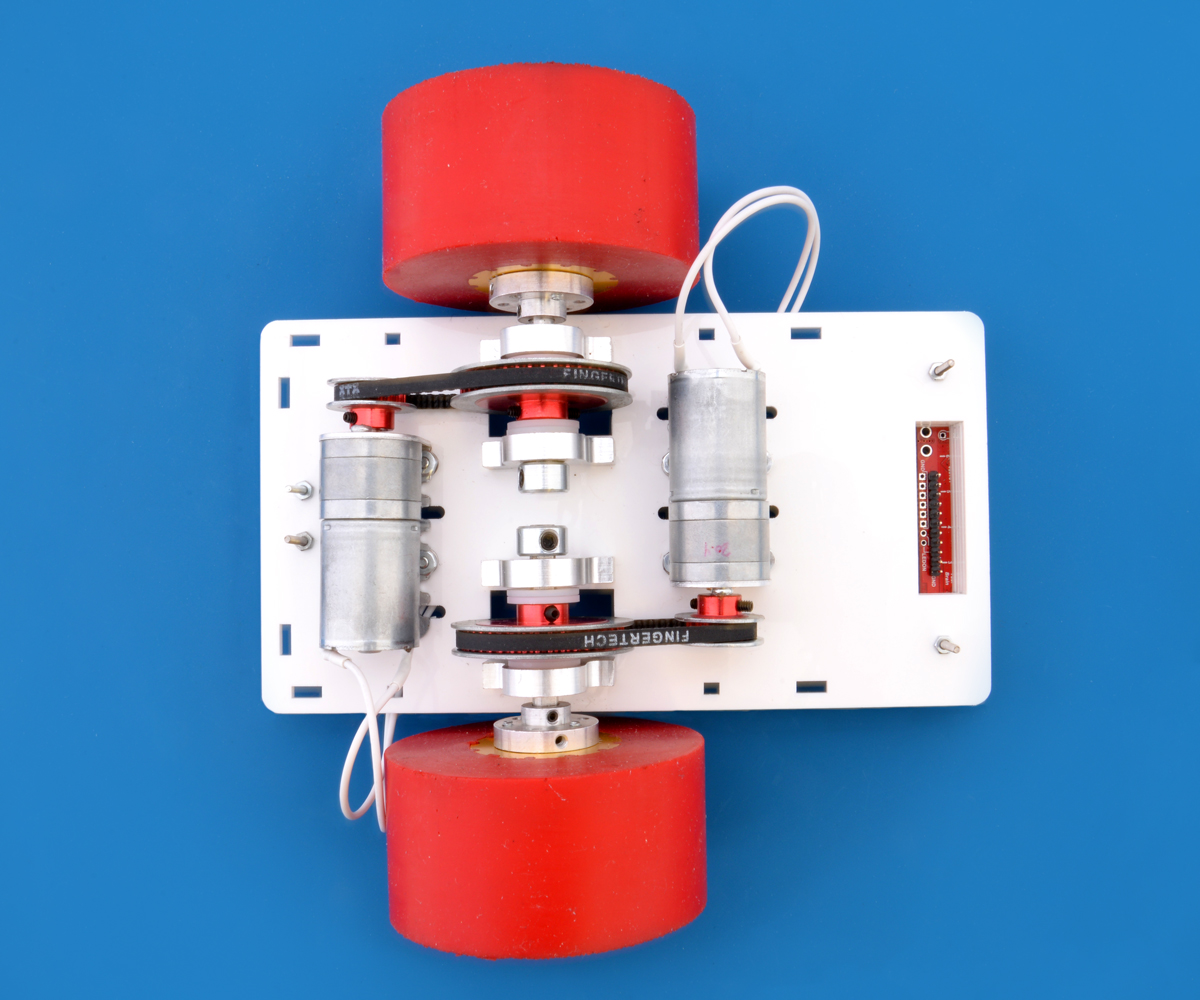
My initial plan for my robot was to get wheels with a lot of traction and to scale up the motors so that I would have a lot of output power to work with. I chose some polyurethane sumo wheels made by Fingertech Robotics as my starting point because they seemed to have a lot of traction. I noticed that Fingertech robotics also had belts and pulleys, so I decided it might be fun to get some and try them out. To support the belt and pulley system, I bought some shafts and block bearings from ServoCity. Based on the weight of the items I had purchased so far, I estimated I would need to use our more powerful motors, so I chose our high power 20.4:1 25D metal gearmotors and decided to run them at about twice their rated voltage by powering them with an 11.1 V LiPo (with the understanding that I would be shortening their operational lifespan by doing so).
 |
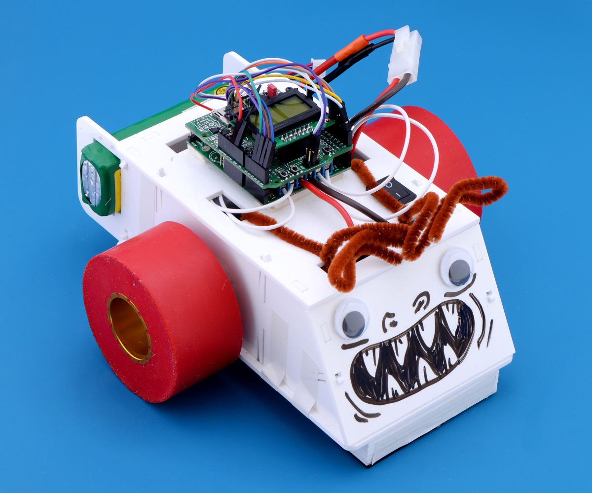
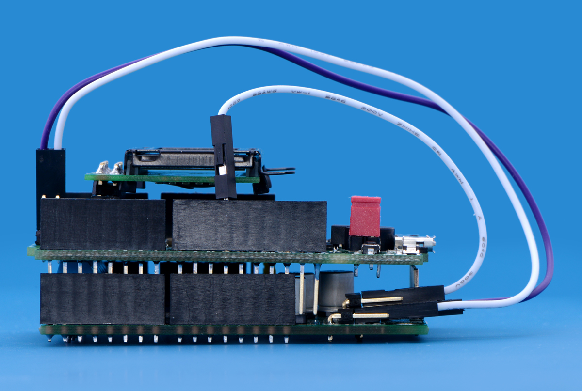
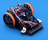
Inside view of Pinto. |
|---|
I chose the dual VNH5019 shield for Arduino as my motor driver because it could continuously supply both motors with more than their stall current at 11.1V. (The stall current of the motors would be about 12 A when the 11.1 V battery was charged, and the VNH5019 dual motor shield could supply 12 A per channel continuously). On the first version of Pinto, I controlled the shield from a Baby Orangutan B-328. However, since the last competition we have released the A-Star Prime. I decided the A-Star Prime was a much better choice since I could use the VNH5019 shield as an actual Arduino shield (simplifying the connections), and I would also gain a buzzer, an LCD, and a USB interface.
Designing a chassis and assembling my robot
The reason that my robot fell apart at the competition last year was that the fasteners kept vibrating loose. To avoid the same mistakes and also to try and make things easier to disassemble when troubleshooting, I decided to try and refrain from using fasteners and to use lock washers when I did not have a good alternative. As the main method of holding my chassis together, I used clips designed into the different chassis pieces, and then had those pieces cut out of 3mm acrylic using our custom Laser cutting service.
 |
Drawings of the custom laser cut pieces that make up Pinto. |
|---|
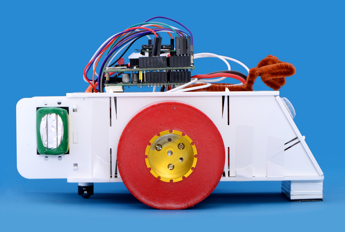
Since I was also going to use the QTR-8RC sensor array, I decided that I could also build something into the chassis that would help shield the sensors from ambient IR light. My solution was the stack of white acrylic pieces under the front of the robot that can be seen in the pictures below.
|
|
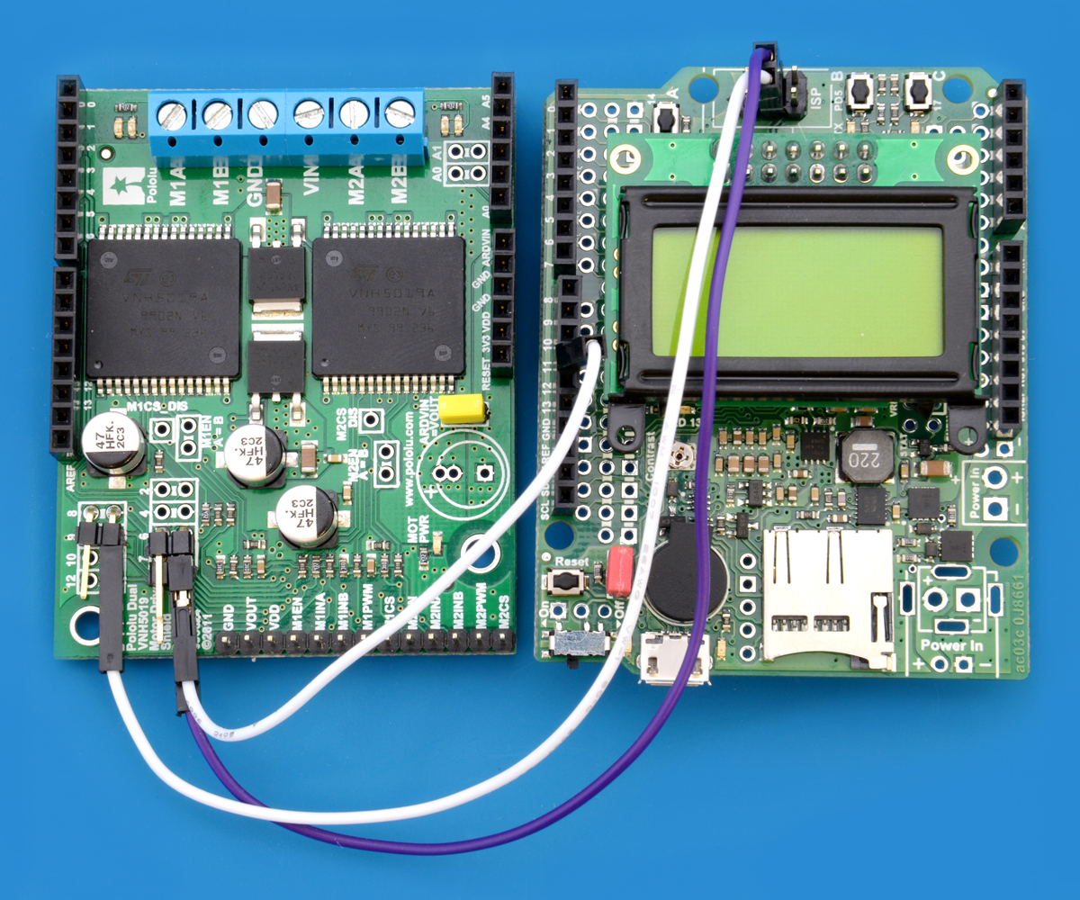
For the electronics, using the A-Star 32U4 Prime made things a lot easier for several reasons. For example, the onboard regulator meant I could power the QTR sensor directly from the A-Star without worrying about its current draw. Also, as I mentioned earlier, the location of the pins matching those of an Arduino meant that it could be plugged into the VNH5019 shield. However, there were two issues about using the VNH5019 as a shield with the A-Star Prime. The first was that if the shield was used in the same way it is with an Arduino, then the LCD and buttons would become unavailable because by default the button and screen are on top of the A-Star where the shield would normally be. To remedy this, I switched the female headers used on each board so that the A-Star Prime sat on top of the VNH5019 shield instead of the other way around. The second issue was that some of the pins used by the VNH5019 shield were already being used by the A-Star Prime for things like the buzzer and LCD. To fix this issue, I remapped the VNH5019 shield connections and modified the code to reflect the changes in the pins. This was pretty simple to do because the VNH5019 shield has a spot on the board to do the remapping. We even have a section in the user’s guide called “Remapping the Arduino Connections” that helps explain how to do this. Below are pictures showing the remapped pins and the two boards stacked on top of one another as well as a table showing all the pin assignments for Pinto.
|
|
| A-Star Prime pin label | Digital pin assignment | Purpose | Note |
|---|---|---|---|
| 0 | 0 | QTR sensor | White wire |
| 1 | 1 | QTR sensor | Yellow wire |
| 2 | 2 | VNH5019 shield | |
| 3 | 3 | QTR sensor | Gray wire |
| 4 | 4 | VNH5019 shield | |
| 5 | 5 | QTR sensor | Orange wire |
| 6 | 6 | Buzzer | |
| 7 | 7 | LCD | |
| 8 | 8 | LCD | |
| 9 | 9 | VNH5019 shield | |
| 10 | 10 | VNH5019 shield | |
| 11 | 11 | VNH5019 shield | Remapped on the VNH5019 shield from pin 6 |
| 12 | 12 | VNH5019 shield | |
| 13 | 13 | LCD | |
| - | 14 | Button A/LCD | |
| - | 15 | VNH5019 shield | Remapped on the VNH5019 shield from pin 7 |
| - | 16 | VNH5019 shield | Remapped on the VNH5019 shield from pin 8 |
| - | 17 | Button C/LCD | |
| A0 | 18 | VNH5019 shield | |
| A1 | 19 | VNH5019 shield | |
| A2 | 20 | QTR sensor | Green wire |
| A3 | 21 | QTR sensor | Purple wire |
| A4 | 22 | QTR sensor | Brown wire |
| A5 | 23 | QTR sensor | Blue wire |
Code
Before I began coding my robot, I laid out a plan of how I wanted the program to be. From past line following competitions, I knew that once you got a working code that a lot of time would then be spent tuning PID constants. With this in mind, I decided that my program should allow me to tune my constants on the go and not force me to return to my computer to make changes to the various values used in the line following code. This is where having the LCD on the A-Star 32U4 Prime became really helpful. The LCD allowed me to create a menu system in which I could display the values used by the program and change them. The menu system worked as intended, and I was able to cut down significantly on the time I used to tune the PID constants (relative to how long it seemed to take everyone else). In addition to the ability to change the PID constants, I also programmed the ability to modify the speed and check the QTR sensor readings in the menu.
Competition day and continuing to improve
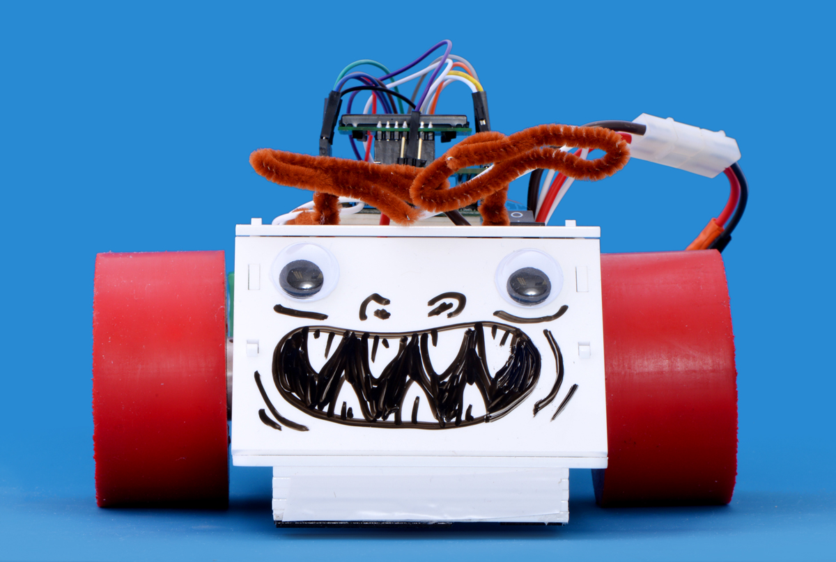
I actually did not name my robot Pinto until the day of the competition. When asked for a name, I gave Pinto because the LiPo battery mounted on the back reminded me of how the Ford Pinto was known for catching fire when it was on the receiving end of a rear-end collision. By competition time, I had only managed to tune the PID constants for up to about 60% of the max speed, so I did not do that well in the competition. One good thing about Pinto’s performance was that it did not seem to lose traction when it was going, so I can probably get more speed if I revisit this robot and tune it at those higher speeds. Some other problems I noticed with my robot is that over time the set screws would become loose on the pulleys and cause slack in the drive system. Also, the clips holding the chassis together seemed inadequate for the size and weight of my robot. In fact, one of the times I was running Pinto, it got away from me and dropped to the floor (from less than a foot off the ground). As a result, all the clips holding the bottom piece broke off. Luckily I was able to tape up the chassis before competition and still run it. From that experience, I learned that I should use something stronger than acrylic clips, I should add something onto my robot to make it easier to grab, and I should add something so my robot stops when it gets off course. Next time we have a line following competition, I plan on using the same parts but redoing the chassis to remedy the problems I experienced.
Related products


-
Nathan's line following robot: Suckbot
- 26 May 2015After branching off into maze solving, pushing into sumo, and finding our way through dead reckoning, we circled back and had another line...
-
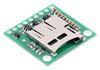
New product: Breakout Board for microSD Card with 3.3V Regulator and Level Shifters
- 29 May 2015In September of last year, we started carrying our Breakout Board for microSD Card, which was the first board that I ever designed and routed here...
0 comments
Post a comment


Home | Forum | Blog | Support | Ordering Information | Lists | Distributors | BIG Order Form | About | Contact
© 2001–2026 Pololu Corporation


