Pololu Blog »
New revision of the Dual VNH5019 motor driver shield for Arduino
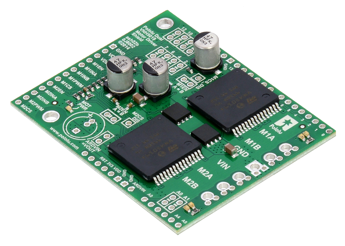 |
We’ve released an updated version of our dual VNH5019 motor driver shield for Arduino. The VNH5019 is a great solution for driving high-power motors, with each chip able to supply up to 12 A continuously at 5.5 V to 24 V. However, the original version of our dual VNH5019 shield was designed before the Arduino Uno R3 was released, so it lacked pass-throughs for the four new pins (SCL, SDA, IOREF, and an unused pin) introduced by the R3 and present on all newer Arduinos. This makes it harder to stack other shields with it, especially ones that make use of the new I²C pin location. The latest board revision adds these pass-throughs to make the shield fully compatible with the Uno R3 pinout.
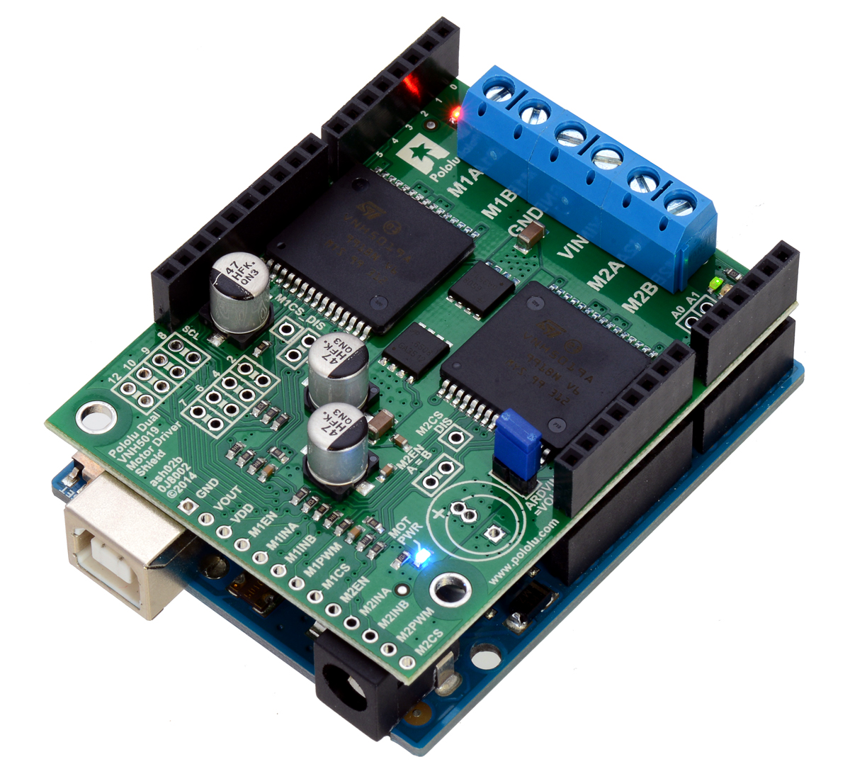 |
For more information, see the dual VNH5019 motor driver shield product page and user’s guide.
Related products


-
New products: 500mA Step-Down Voltage Regulator D24V5Fx
- 24 March 2014We are happy to introduce our D24V5Fx voltage regulator family, a next-generation version of our tiny D24V3Fx and D24V6Fx buck (step-down)...
39 comments

Is it possible to use two of these cards with an Arduino mega to control 4 motors?
Thanks,
Rebecca

It is possible to use more than one dual VNH5019 shield on an Arduino, but it would require a lot of changes to get it to work. You would have to remap the control pins, do some additional wiring, and write your own code to set up PWM on the correct pins for all of the shields.
You can read more about how to make some of those changes inside the "Remapping the Arduino Connections" section of the VNH5019 shield's user's guide, which can be found under the Resources tab of its product page:
http://www.pololu.com/product/2507/resources
By the way, we break out the connections to the motor drivers along a single side of the shield, so if you do not need to stack the shields, you could just make your logic connections there. This might make using both shields easier.
You can find a similar forum post here:
http://forum.pololu.com/viewtopic.php?f=15&t=4875
-Jon

I have the previously version of this driver.
My question is about the PWM interpretation behavior of this driver.
I've tested to send some PWM fractions to see the output Voltage behavior.
It was not linear.
I had a LiPo 11,7 volts battery connected. However, to get 6V output signal, I had to send a PWM signal of 50 (max. 255).
My doubt is, was it supposed to have a linear behavior? I mean, to get aprox. 6V, send a PWM of 255/2.
The second question is: How do I set the driver to provide 5V output to power the Arduino? I saw here I just have to put the jumper in. It didn't work.
Thanks!! Your products are very good, by the way.

The VNH5019 operates in drive-coast mode, so its output is generally not very linear. If you want to get a very linear output then some kind of feedback is probably needed.
The VNH5019 shield does not regulate the voltage it supplies to the Arduino, the jumper simply connects the reverse protected VIN voltage to the Arduino's Vin.
If you are having trouble using your VNH5019 shield, you could post pictures and more technical details about the issue on our forum.
- Grant

Goal:
Can the dual VNH5019 motor driver shield for Arduino operate on the "Makeblock Configurable 4WD Robot Kit - Blue" on all 4 motors if two on each side were connected in parallel to one of the two drivers?
Operation:
So they can either move forwards and backwards but also turn around.
Thanks Noob...
In general, we usually recommend using a motor driver that has a continuous current rating greater than the stall current of your motor. From the motor specifications I found on this website, it seems like you should be able run two of those motors from each channel on the VNH5019.
- Grant
I'm trying to power the arduino by this motor driver but I keep getting zero Volts in VOut port nor VDD port.
How do I enable it? Could you help me?
Thanks,

I am sorry you are having problems with your VNH5019 shield. However, the blog is not an appropriate place for troubleshooting your problem. Instead, you might post this on our forum with more details about your setup.
- Jeremy


As long as the specifications of your modified bilge pump are similar to those of the bilge pump you linked to, I do not see any obvious reasons why it wouldn't work.
-Brandon

Can i use this drive to control(with arduino), two servo motor with 10A?
and, the code, can be the same of any servo motor?
Since now, i thank you.

It is not clear if you are talking about RC hobby servos or motors that have been removed from inside of some servos. If you are looking for a controller to command servos, you might consider one of our Maestro USB Servo Controllers. This shield works with brushed DC Motors, and each channel can handle 12 A continuously. You can find example code and libraries in the " Programming Your Arduino" section of the " Pololu Dual VNH5019 Motor Driver Shield User’s Guide"
-Derrill

I just have a quick question.
In order to have this motor driver take a position input, is there any specific command available.
I know that you can set the speed by void setM1Speed(int speed) but I need my motor to go to a specific encoder position.
Now, what I have done is that according to its current angular position (Encoder Reading) I made it move the correct direction and as it gets closer to that position it slows down and set the speed to zero when it gets close enough.
The problem is that it kind of oscillates close to the required position some times.
Am I doing this correctly or is there a more appropriate way of doing this?
Thanks for your feedback in advance.
Cheers,
Sina

The motor driver library functions aren't the right place to look. You are on the right track by controlling the motor speed based on the position. What you are doing is called proportional feedback control. You can smooth it out by using PID control. You can learn the basics here https://www.youtube.com/watch?v=UR0hOmjaHp0&list=PLUMWjy5jgHK20UW0yM22HYEUTMJfla7Mb and then write some code for it. You might be able to adapt the 3pi line-following code here https://www.pololu.com/docs/0J21/7.c to fit your application. For additional questions, we hope you'll post on our forum, where your questions will have more visibility.
Ryan

The position of the motor and power screw terminals and the pin remapping wire holes are on the exact opposite sides of the board from where they should be for convenience.
By switching the sides for the motor and power screw terminals and the pin remapping wire holes you give better access to the additional pins on boards like the mega. This would also allow for shorter wire runs when stacking the boards and remapping pins.
The only other suggestion is to consider changing the pin out such that no pins are on pins 0,1,2,3. This would make it easier to use with an Xbee shield in Dline mode (pins 2 and 3 are the other TX, RX lines on the UNO and are used by Xbee shields for communication. With pins 0 and 1 being TX, RX for UART with the USB for programming)

Thanks for the compliments on our driver and the great feedback! It would be convenient for all of the external connections to the shield and controller to be on one side and for the remapping jumpers to be closer to extra I/O pins. Unfortunately, the USB connector and barrel jack on the Arduino Uno would interfere with the leads of the terminal blocks that stick out the bottom of their through holes if we were to just move them to the opposite edge of the board. As for the pin mapping, we tried to pick the least useful Arduino pins that could work with our shield. It's hard to avoid incompatible pin choices with so many different shields people might want to combine. We will keep all of your feedback in mind for any future revisions or shields.
-Claire
I have a question about the vnh5019 library for arduino. I'm not sure if you guys support this or not. I need to drive my motor from simulink which uses serial communication with arduino. So, I was just wondering if there is any way not to use this library to run the motor! I need to input some voltage patterns to the arduino so that it runs the motor. But this would need the library and the motor speed as inputs.
Please advise.
Thanks.
Sean :)

You can run your motors from the VNH5019 motor driver shield without using our Arduino library. The library just makes it easier to get started using the board as a motor driver shield. You can directly send logic level signals to the board's logic connections, which we break out on the left side of the shield. If you do use the shield as a general purpose driver, I suggest looking at the VNH5019 datasheet for information not covered in the VNH5019 user's guide.
We do not use Simulink here, so we cannot really help you with it. If you need more help, you can post your question on our forum or to the MathWorks User Community, which should have a bigger community of people who are more familiar with programming with Simulink.
- Amanda

Is there a driver for Intel Edison - UPM Libs
http://iotdk.intel.com/docs/master/upm/group__motor.html
Thanks,
-Dai

We do not know of a driver or library for the Intel Edison and this shield.
-Nathan

I want to control 2 motors but I would like twice the rated current capacity of one of the VNH5019 board.
I would like to stack two of the VNH5019 shields on an arduino and wire the motor A outputs together to one motor and the B outputs together to another motor. My hope is that this would double the current I can draw with each motor while using the standard pin assignmants and code. Is this correct?
Thank you for your help!
-Tyler
We tried running the VNH5019 motor driver in parallel by stacking two shields, and it seemed to work (we tested it up to about 12A); however, please note that this is not the method suggested by the VNH5019 datasheet. It recommends using each of the ICs as a half-bridge for combining VNH5019 drivers to increase the maximum current draw. You can read more about this in the "Using the Driver in Single-Channel Mode" section of the Dual VNH5019 Motor Driver Shield User’s Guide.
If you have more technical questions about the dual VNH5019 motor driver shield, our forum is a great place to ask them.
- Jeremy

I am using the Dual Motor Driver in single channel mode and it is behaving as intended, which is always nice. My question relates to the best way to incorporate real-time current limiting based on some external measured motor current. From what I can see the current measurement features are disable when using the single channel mode so I have additional current sensing circuitry in place feeding the Arduino with an analog voltage input.
Some info related to the setup: The required motor for my torque requirements has a stall current of 32A. The normal rated running current is 16A. So my power supply is sufficient and the combined continuous running current of the Pololu shield is sufficient. I have seen here that I should have a driver that is capable of delivering more than the Stall Current... Is this always the case with these shields?
I also have a simple joystick 5k pot as input to the motor. The value of which is sampled, then mapped to +/-400 to send to the md.setM1Speed().
I also intend to monitor current inside the main loop. If my measured current approaches a threshold of say 18A what is the best way to handle the throttling of command to the Motor Driver? Ultimately I don't want the current limiting capabilities of the Dual Motor Driver OR my power supply to kick in and cut drive completely... I would just like it to ramp back smoothly until the over-current condition fades away...
Any help would be massively appreciated. The info on this site is awesome. Nice job with the tutorials and blogs... Nothing like this here in Australia.
Cheers
Sean
Thank you for the kind words; I am glad you find our website helpful!
As you mentioned, we typically recommend using a driver that can handle the stall current of your motor continuously since this results in a more robust system. You can generally get away with a lower-power driver than this, but then you have to be more careful with how you use your motor since it would be capable of exceeding the abilities of the driver. I think the idea of using an external current sensor is a good one since you can use the feedback to stay within the rated continuous current of your motor (which the VHN5019 shield should be able to comfortably handle in single-channel mode).
Your strategy of monitoring the current sounds good, but keep in mind that current spikes can be very quick and, depending on your system, might trigger an over-current condition in your power supply or driver before your system has a chance to react to them. A good way to avoid such current spikes is to limit motor acceleration (e.g. don't just apply full power to the motor while it is stationary or rotating in the opposite direction; wait for the motor to come to a stop and then gradually ramp up the speed until it reaches the target specified by the joystick input). We do not have any examples for adding that kind of throttling to a system like that, but you might start out by having a correction factor based on the current sensor readings that you subtract from your target speed to get your actual motor speed (e.g. a higher current reading would result in a higher correction factor).
If you try adding in this correction factor into your code and have trouble, I suggest posting on our forum for additional help.
-Brandon

Another blog comment Grant talks about a drive-coast mode which makes me wonder if PWM averaging is going to work on the brushless motors.
Will this motor controller work with the brushless motors?
The brushless phasing is all controlled within the SPAL motors.
Cheers!
Lew
The VNH5019 shield does not work directly with brushless motors. We are not very familiar with SPAL motors, so we are not sure what kind of included circuitry they have. You might ask their manufacturer or someone more familiar with them to see what control solutions they recommend. Alternatively, if you show us some documentation (e.g. a datasheet) for your motors, we might be able to give you a more helpful answer.
-Jon

(I am planning to use a 2cell LiPo battery)
You could use a 6V motor with the VNH5019, and I think that all of our 6V gear motors have stall currents under 12A, so the VNH5019 should be able to handle their current draw. In this case, the thing to note is that using a brushed DC motor with a voltage that is higher than its rated voltage will increase its performance (speed and torque), but will also increase the current draw and decrease the motor's lifetime.
-Claire


I have 24v motors. What will happen if I use this driver on 24V battery?
Thanks
Like we say on the shield's product page: while the shield's overvoltage protection typically kicks in at 27V, it can trigger at voltages as low as 24V, so we do not recommend using this motor driver with 24V batteries, which significantly exceed 24V when fully charged. Specifically what voltage the shield's overvoltage protection kicks in at can vary from unit to unit, so there is a chance that the particular unit you get will not work with a 24V battery.
-Jon


The VNH5019 can supply 12A continuously per motor. To be safe, we recommend using a driver that can continuously handle the stall current of your motor. 140mV/A is the scaling factor for the board's current sense output. You can find information about the VNH5019 current sensing feature in the "Current sense outputs" section of the "Pololu Dual VNH5019 Motor Driver Shield User’s Guide", which is located under the Resources tab of its product page.
-Dan

Yes, all the control pins are broken out along the left side of the board to enable use as a general-purpose motor driver controlled by devices other than Arduinos. Section 4 of the user's guide has more information on that.
-Dan

I am looking for a motor driver to take full advantage of the features (torque and velocity) of the two motors I have chosen for my mini sumo. The motors are as follows:
Specifications:
- Operating Voltage: 6 to 16VDC
- Normal Operating Voltage: 6VDC
- Maximum Operating Voltage: 16VDC
- Speed: 800 RPM at 6VDC
- No Stall Current: 190mA
- Operating Current: 260mA
- Stopping Current: 5.75A
- Rated Load Torque: 3.1kg/cm
- Stall Torque: 4.5kg/cm
- Motor Diameter: 16mm
[Link: https://my.cytron.io/p-6v-800rpm-super-power-dc-micro-metal-gearmotor-novamax]
Since the stopping current is 5.75A, I would like to know if I can use this driver for my motors since I would like to keep the current at 6A maximum (do you recommend this?).
If possible, what settings should I keep in mind both in my example Arduino code and in the connections between the shield and the motor to avoid damaging the motor?

The Pololu Dual VNH5019 Motor Driver Shield for Arduino should be a good choice for powering two motors like the ones you are using, though the motor's current requirements might start pushing the boundaries of what the driver can do as you approach the 16V maximum operating voltage for that motor. Keep in mind that as the operating voltage increases, the motor's current draw increases proportionally, so the approximate current draw will be around 2.7 times higher at 16V than at 6V (which is the likely operating point for the current specs you copied since that is listed as the nominal operating voltage).
The best thing you can do to avoid damaging your motor is to just not subject it to loads beyond what it can handle. It might help to limit the supply voltage (or the maximum PWM duty cycle) and implement acceleration/deceleration limiting to avoid sudden impulses. You might also consider using the VNH5019's current sense feedback to monitor the motor's current draw and signal to reduce power or turn the motors off if the current gets too high. A good rule of thumb is 20-25% of the stall torque/current. However, that advice can be at odds with the objectives for a Sumo competition, so it is ultimately up to you to assess the risks and benefits of how you try to protect your motors, and to what degree.
- Patrick
Post a comment


Home | Forum | Blog | Support | Ordering Information | Lists | Distributors | BIG Order Form | About | Contact
© 2001–2026 Pololu Corporation
