TI Robotics System Learning Kit MAX (TI-RSLK MAX) Parts and Accessories »
8-Channel QTRX Sensor Array for Romi/TI-RSLK MAX (Headers Not Soldered)

This reflectance sensor module is designed specifically for use with Romi or TI-RSLK MAX robots based on the TI-RSLK Chassis Board v1.0. It features eight IR LED/phototransistor pairs that are great for identifying changes in reflectance on the ground underneath the robot (like detecting or following a black line on a white background). The sensor array offers dimmable brightness control with separate controls for the odd and even emitters, and each sensor provides an independent output that can be measured with a digital I/O. This version includes extended male header pins, but they are not soldered, so soldering is required to use this product.
 Compare all products in TI Robotics System Learning Kit MAX (TI-RSLK MAX) Parts and Accessories.
| Description | Specs (14) | Pictures (16) | Resources (4) | FAQs (0) | On the blog (0) | Distributors (1) |
|---|
Overview
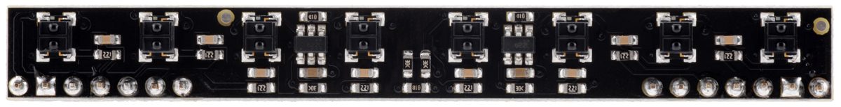 |
Sensor side of the 8-Channel QTRX Sensor Array for Romi/TI-RSLK MAX. |
|---|
This reflectance sensor array is an easy way to add line sensing to a Romi or TI-RSLK MAX robot based on the TI-RSLK Chassis Board v1.0. It features a linear array of eight reflectance sensors, each consisting of a dimmable IR emitter coupled with a phototransistor that responds based on how much emitter light is reflected back to it. The sensors are spaced on a 3/8″ (9.5 mm) pitch, which works well with line courses made from 3/4″ black electrical tape on a white background.
|
|
|
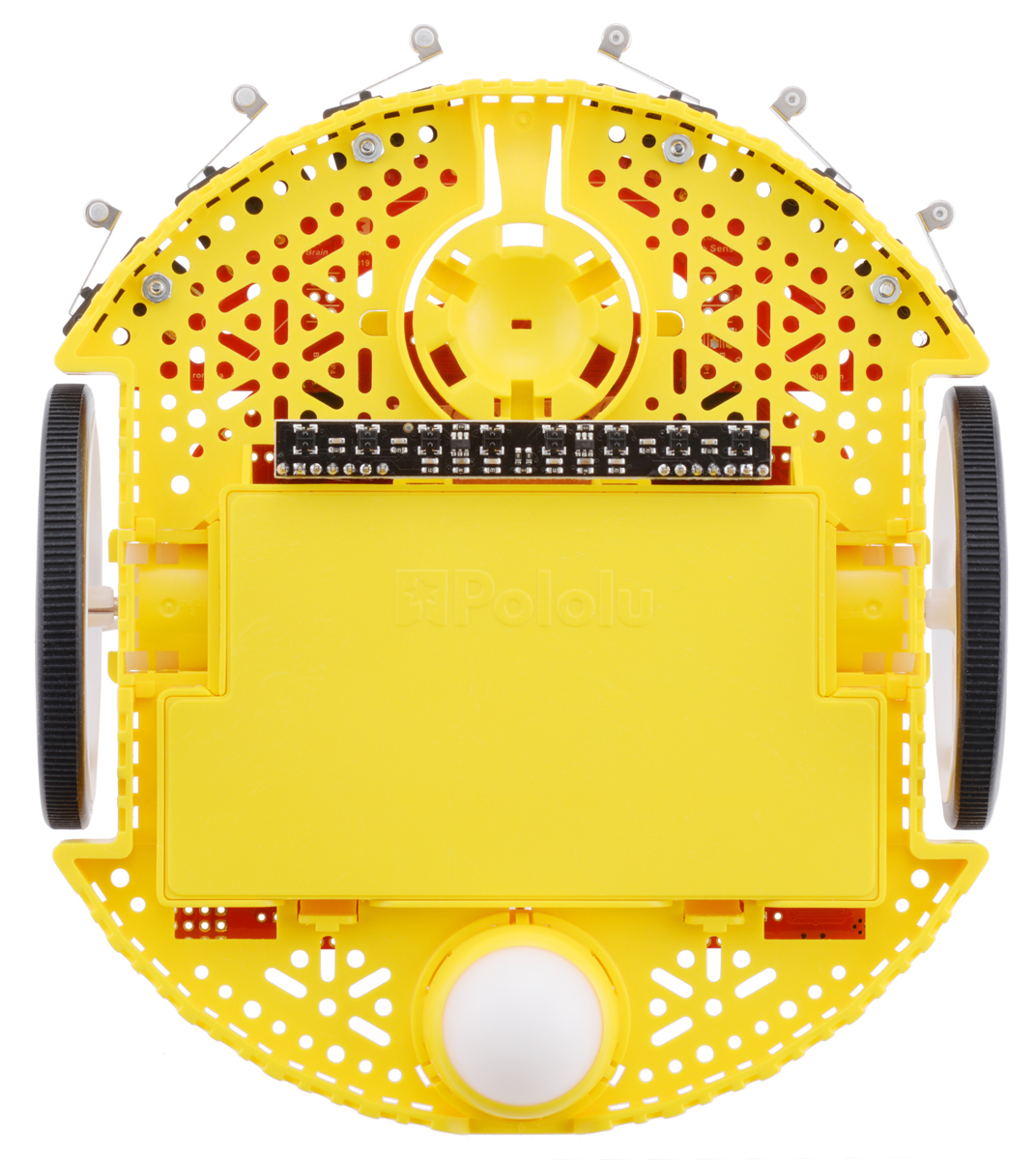


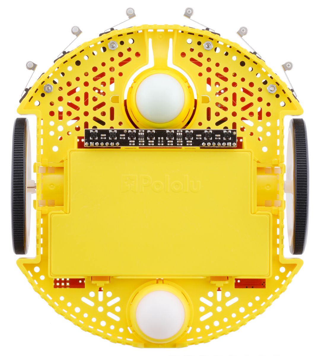
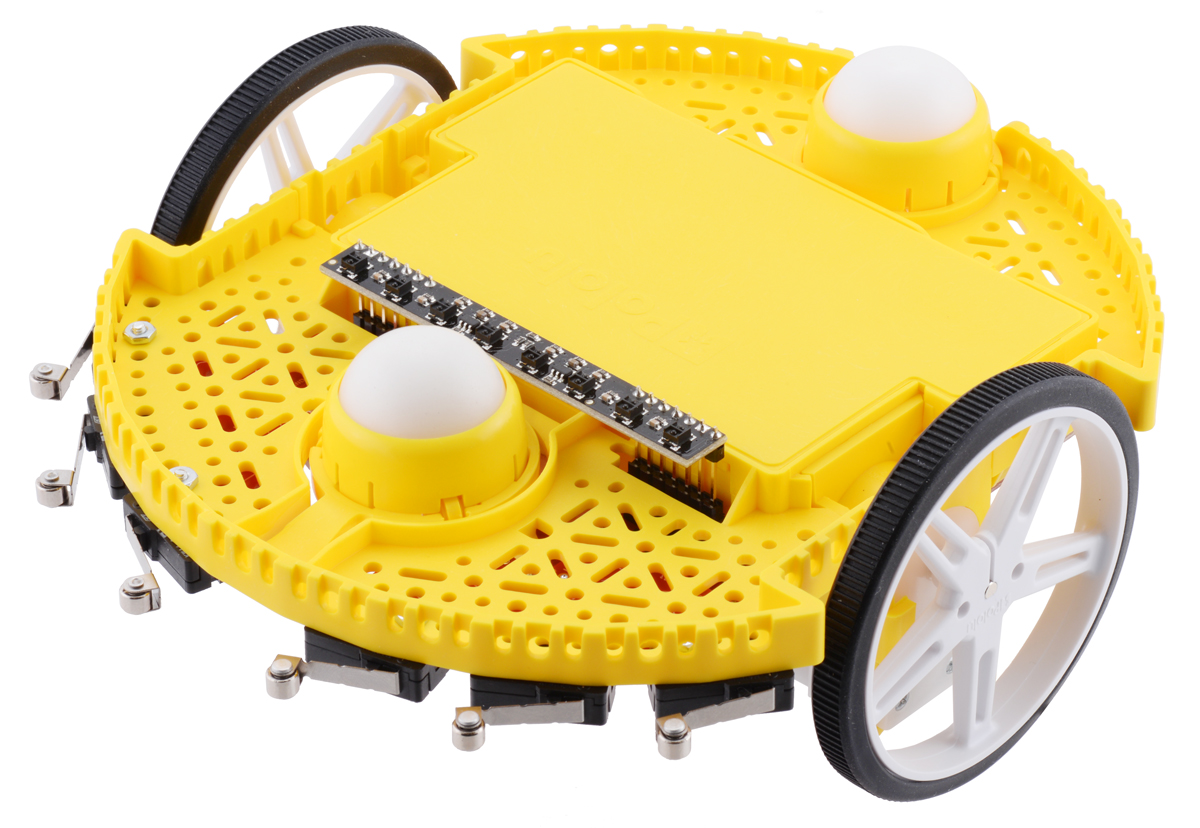
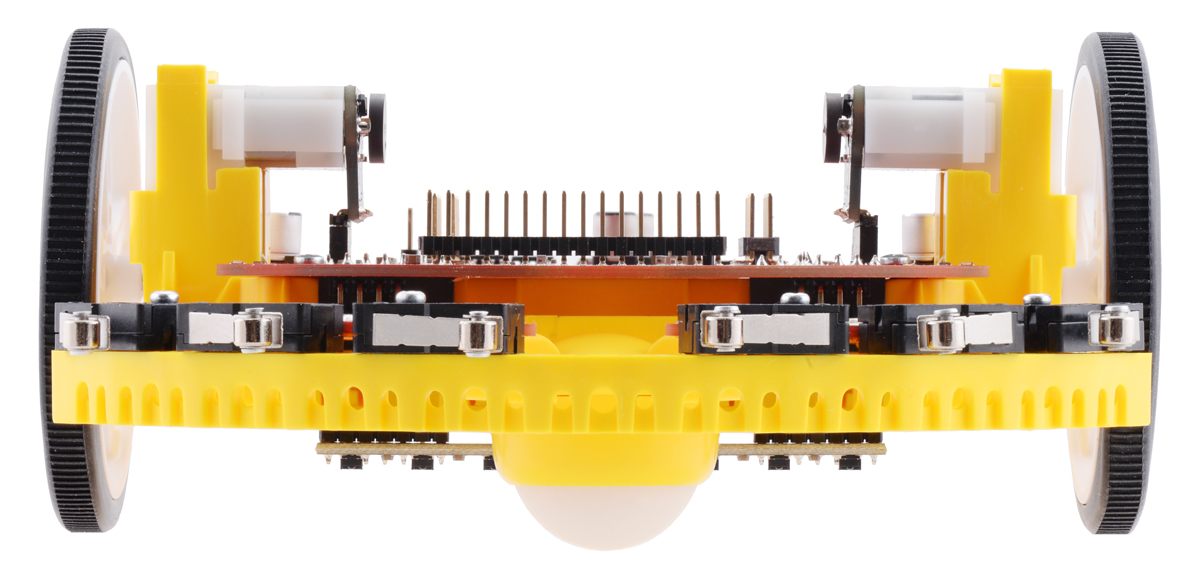
The reflectance sensor plugs into corresponding female headers on the underside of the Chassis Board, just in front of the battery box and behind the receptacle for the optional front ball caster. The pictures below show what the Romi chassis looks like with both the reflectance sensor array and front ball caster:
|
|
|
Details for item #3545
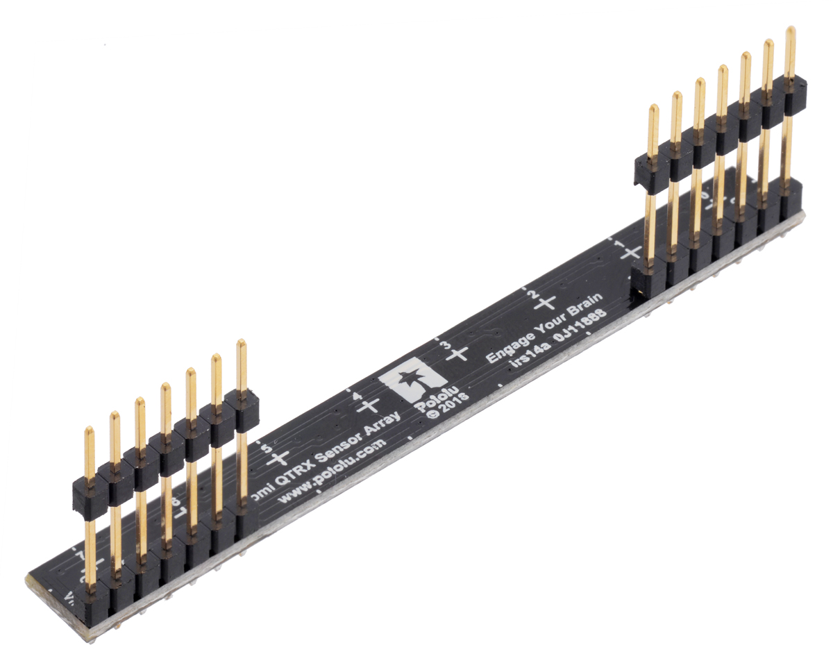
This version of the QTRX Sensor Array for Romi/TI-RSLK MAX includes extended male headers, but they are not soldered in, so soldering is required to use this product.
|
This sensor array is also available with headers soldered and ready to plug directly into the Chassis Board from below.
 |
Specifications
- Dimensions: 3.0″ × 0.35″ × 0.14″ (see the dimension diagram (373k pdf) for more details)
- Operating voltage: 2.9 V to 5.5 V
- Sensor type: QTRX
- Sensor count: 8
- Sensor pitch: 3/8″
- Full-brightness LED current: 3 mA (independent of supply voltage)
- Max board current: 15 mA
- Output format: digital I/O-compatible signals that can be read in parallel as timed high pulses
- Weight: 4.2 g with headers
Using the sensor array
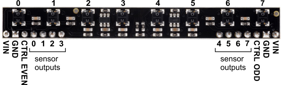 |
Pinout
When a Texas Instruments MSP432 LaunchPad is plugged into to the TI-RSLK MAX Chassis Board v1.0, its pins connect to sensor array pins as follows:
| Sensor array pin | TI-RSLK MSP432 pin | Description |
|---|---|---|
| VIN | 5V | 5 V power |
| GND | GND | Ground |
| CTRL EVEN | P5.3 | Emitter control pin for even-numbered sensors (pulled to logic high by default) |
| CTRL ODD | P9.2 | Emitter control pin for odd-numbered sensors (pulled to logic high by default) |
| 0 | P7.0 | Reflectance sensor outputs |
| 1 | P7.1 | |
| 2 | P7.2 | |
| 3 | P7.3 | |
| 4 | P7.4 | |
| 5 | P7.5 | |
| 6 | P7.6 | |
| 7 | P7.7 |
Reading the sensors
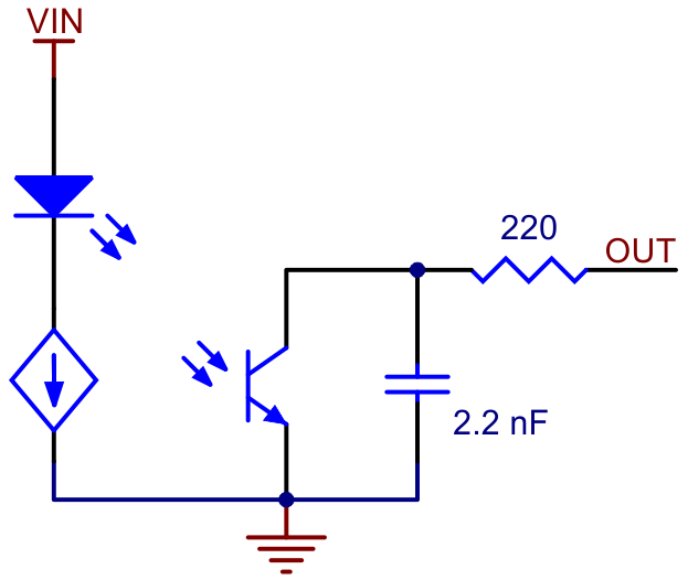 |
Schematic diagram of an individual RC sensor channel. |
|---|
This array uses the same sensor modules as our QTRX reflectance sensors and has the same principle of operation as the RC versions (e.g. the QTRX-MD-08RC). The typical sequence for reading a sensor is:
- Turn on IR LEDs (optional).
- Set the I/O line to an output and drive it high.
- Allow at least 10 μs for the sensor output to rise.
- Make the I/O line an input (high impedance).
- Measure the time for the voltage to decay by waiting for the I/O line to go low.
- Turn off IR LEDs (optional).
These steps can typically be executed in parallel on multiple I/O lines.
With a strong reflectance, the decay time can be as low as a few microseconds; with no reflectance, the decay time can be up to a few milliseconds. Meaningful results can be available within 1 ms in typical cases (i.e. when not trying to measure subtle differences in low-reflectance scenarios), allowing up to 1 kHz sampling of all sensors. If lower-frequency sampling is sufficient, you can achieve substantial power savings by turning off the LEDs. For example, if a 100 Hz sampling rate is acceptable, the LEDs can be off 90% of the time, lowering average current consumption from 15 mA to under 2 mA.
|
|
Emitter control
 |
Demo of IR LED dimming on the 8-Channel QTRX Sensor Array for Romi/TI-RSLK MAX (as seen through an old digital camera that can see IR). |
|---|
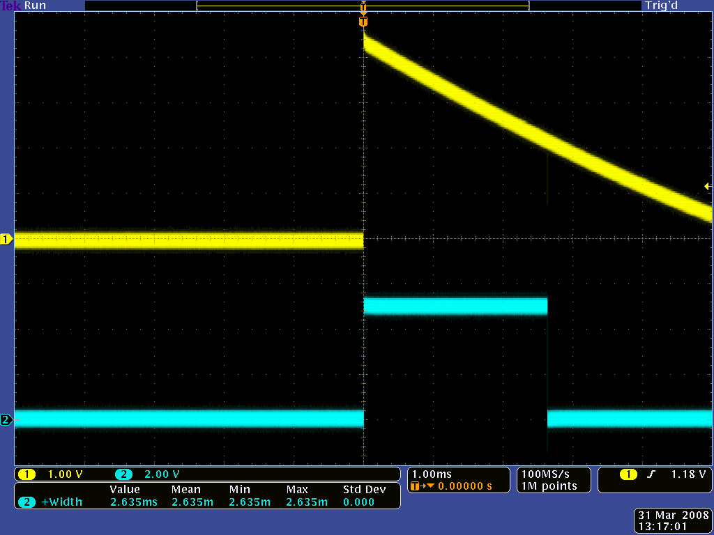
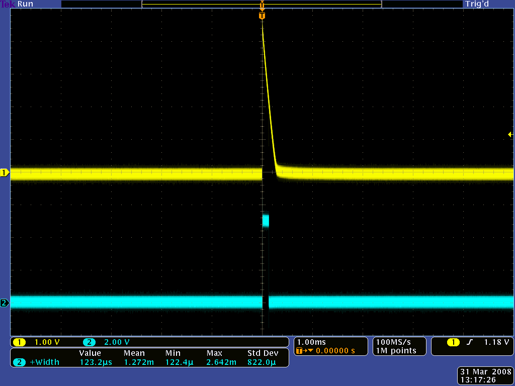
The sensor array maintains a constant current through its IR emitters, keeping the emitters’ brightness constant. The emitters can be controlled with the board’s two CTRL pins, CTRL ODD and CTRL EVEN. By default, these are connected together with a 1 kΩ resistor and pulled up, turning on all the emitters by default and allowing them to be controlled with a signal on either pin. However, the CTRL ODD and CTRL EVEN pins can be driven separately for independent control of the odd-numbered and even-numbered emitters.
Driving a CTRL pin low for at least 1 ms turns off the emitter LEDs, while driving it high (or allowing the board to pull it high) turns on the emitters with the board’s default (full) current, which is 3 mA. For more advanced use, each CTRL pin can be pulsed low to cycle the associated emitters through 32 dimming levels.
To send a pulse, drive the CTRL pin low for at least 0.5 μs (but no more than 300 μs), then high for at least 0.5 μs; (it should remain high after the last pulse). Each pulse causes the driver to advance to the next dimming level, wrapping around to 100% after the lowest-current level. Each dimming level corresponds to a 3.33% reduction in current, except for the last three levels, which represent a 1.67% reduction, as shown in the table below. Note that turning the LEDs off with a >1 ms pulse and then back on resets them to full current.
| Dimming level (pulses) |
Emitter current (%) |
Dimming level (pulses) |
Emitter current (%) |
|
|---|---|---|---|---|
| 0 | 100.00% | 16 | 46.67% | |
| 1 | 96.67% | 17 | 43.33% | |
| 2 | 93.33% | 18 | 40.00% | |
| 3 | 90.00% | 19 | 36.67% | |
| 4 | 86.67% | 20 | 33.33% | |
| 5 | 83.33% | 21 | 30.00% | |
| 6 | 80.00% | 22 | 26.67% | |
| 7 | 76.67% | 23 | 23.33% | |
| 8 | 73.33% | 24 | 20.00% | |
| 9 | 70.00% | 25 | 16.67% | |
| 10 | 66.67% | 26 | 13.33% | |
| 11 | 63.33% | 27 | 10.00% | |
| 12 | 60.00% | 28 | 6.67% | |
| 13 | 56.67% | 29 | 5.00% | |
| 14 | 53.33% | 30 | 3.33% | |
| 15 | 50.00% | 31 | 1.67% |
For example, to reduce the emitter current to 50%, apply 15 low pulses to the CTRL pin and then keep it high after the last pulse.
Schematic diagram
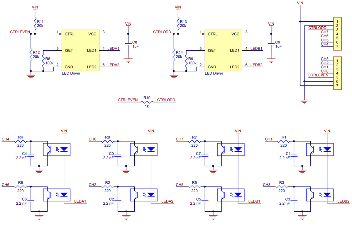 |
This diagram is also available as a downloadable pdf (109k pdf).
Related products


Home | Forum | Blog | Support | Ordering Information | Lists | Distributors | BIG Order Form | About | Contact
© 2001–2026 Pololu Corporation
