Voltage Regulators »
Charge Pump Voltage Inverter: 1.8-5.3V, 60mA

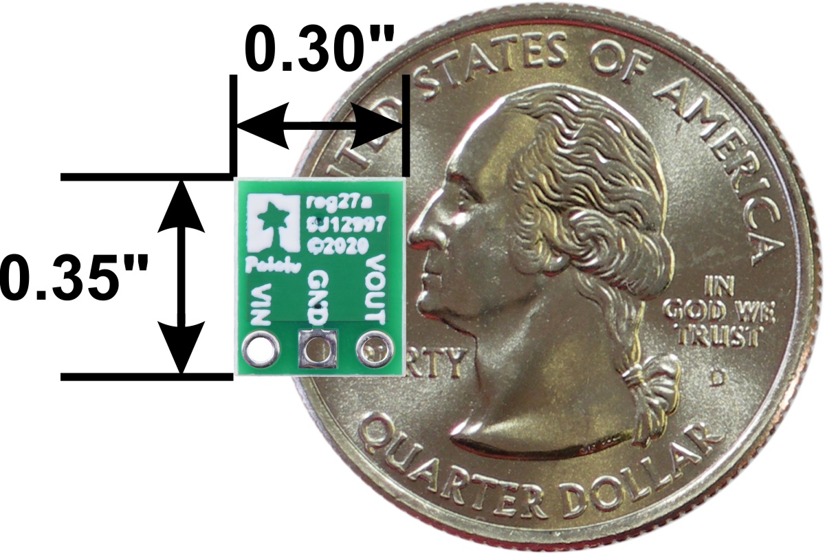
This tiny voltage inverter generates a negative output voltage corresponding to the voltage provided on its input, which can be from 1.8 V to 5.3 V. The compact (0.3″ × 0.35″) module has a typical efficiency of over 80% and can deliver up to 60 mA continuously.
 Compare all products in Voltage Regulators or Voltage Regulators and Power Supplies.
| Description | Specs (8) | Pictures (9) | Resources (3) | FAQs (0) | On the blog (0) | Distributors (50) |
|---|
 |
Overview
This board is a charge pump voltage inverter that converts an input voltage between 1.8 V and 5.3 V to a corresponding negative output voltage, with a typical efficiency of over 80%. The inverter can deliver a continuous output current of 60 mA across most of its operating range, making it a simple solution for applications requiring a lower-power negative supply, including sensor biasing and bipolar op-amp circuits.
Unlike a voltage regulator, which produces a constant output voltage from a range of input voltages, this inverter does not have a set output voltage; the module’s negative output voltage varies proportionally to the positive input voltage that it receives. However, you can get a regulated negative voltage by powering the inverter with a pre-regulated supply voltage. For example, with a fixed 5 V supply, the module produces a fixed −5 V on its output; with a 3.3 V input, the output is −3.3 V. Note that the magnitude of the output voltage decreases as the output current increases; please see the graphs at the bottom of this page for a more detailed characterization.
Features
- Input voltage: 1.8 V to 5.3 V
- Negative output voltage is inverted from input
- Typical continuous output current: 60 mA
- <200 µA typical no-load quiescent current
 |
 |
Using the inverter
Connections
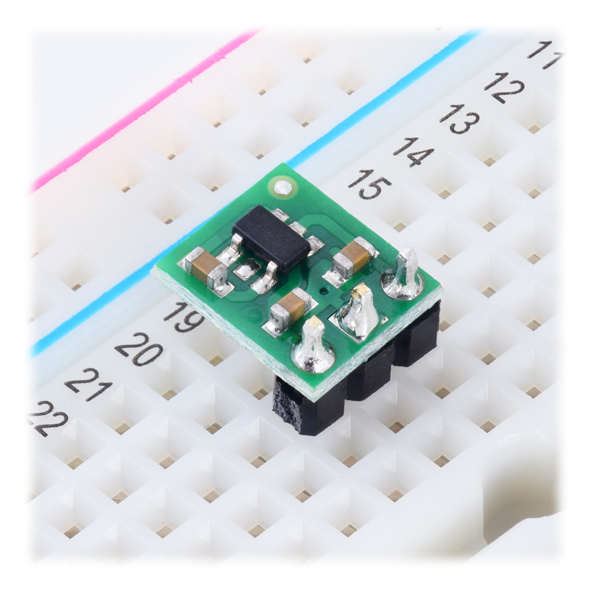
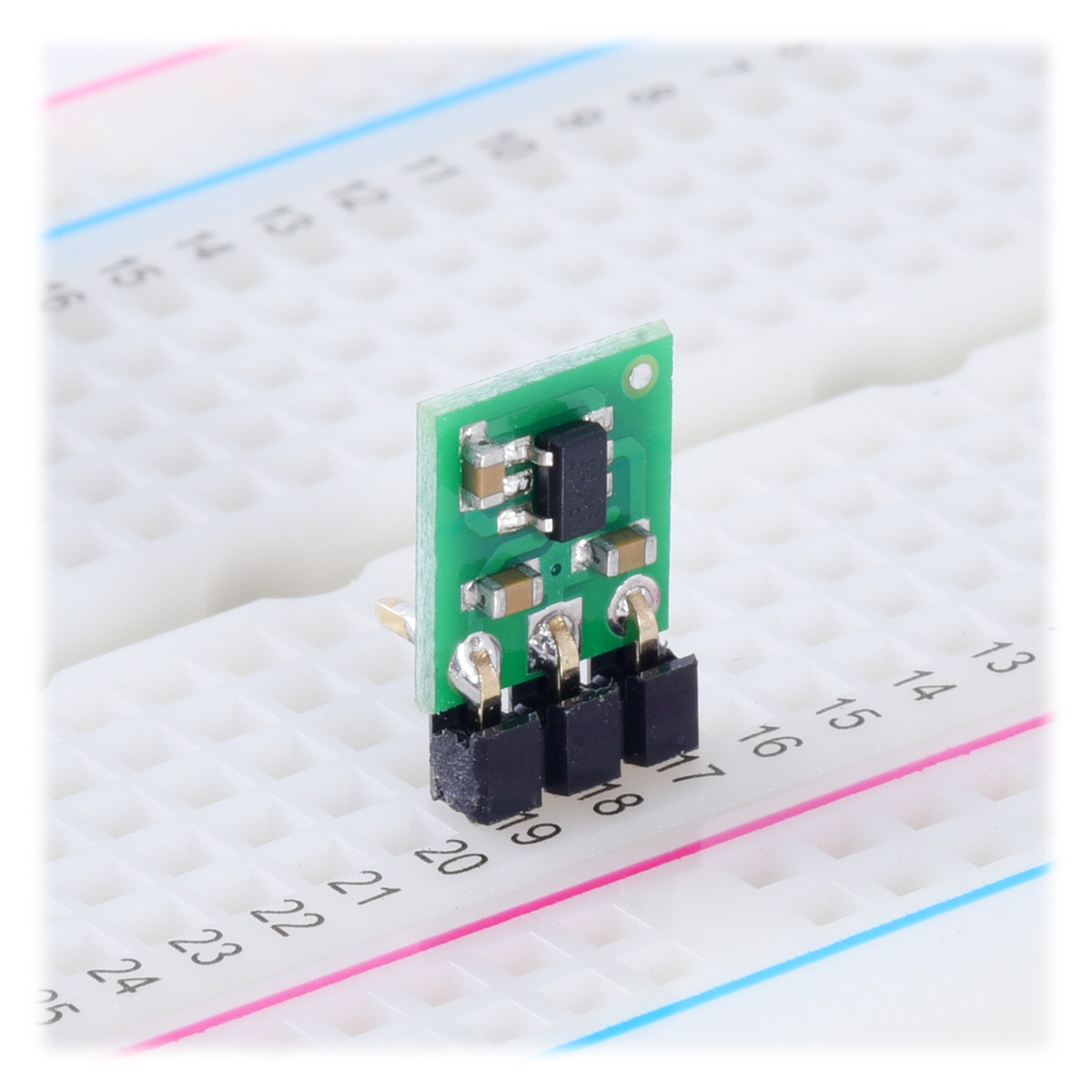
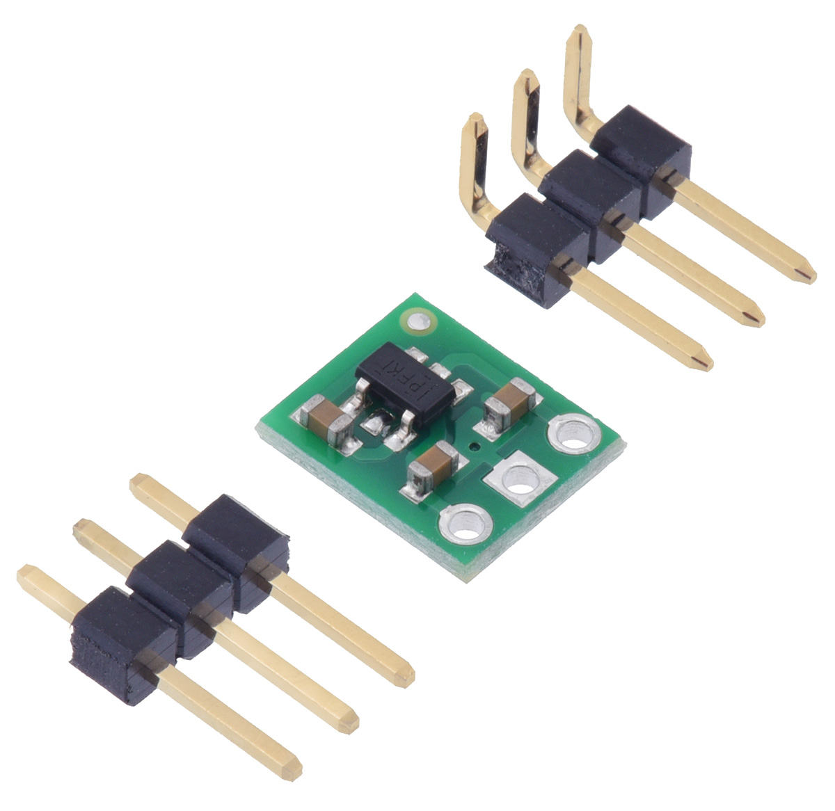
The voltage inverter has three connections: input voltage (VIN), ground (GND), and output voltage (VOUT). The three connections are labeled on the back side of the PCB, and they are arranged with a 0.1″ spacing along the edge of the board for compatibility with solderless breadboards, connectors, and other prototyping arrangements that use a 0.1″ grid. You can solder wires directly to the board or solder in either the 3×1 straight male header strip or the 3×1 right-angle male header strip that is included.
The input voltage, VIN, should be between 1.8 V and 5.3 V. The output voltage, VOUT, is inverted from the input (nominally, VOUT = −VIN).
 |
Typical Efficiency and Output Current
The efficiency of this inverter, defined as (Power out)/(Power in), is an important measure of its performance, especially when battery life or heat are concerns. As shown in the graph below, this voltage converter typically has an efficiency of 80% to 90%.
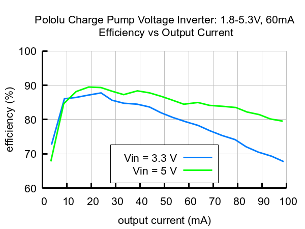 |
The maximum achievable output current is at least 60 mA continuous across most of the voltage inverter’s operating range, but at input voltages below about 2.2 V, the available output current is reduced (down to about 40 mA at 1.8 V in).
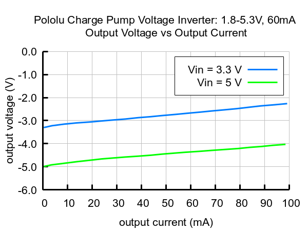
Output Voltage Drop
The output voltage of this inverter is not regulated; it is close to the exact negative of the input voltage when the output current is low, but as the load increases, the magnitude of the output voltage decreases (the output voltage rises toward 0 V) as shown in the graph below.
 |
Related products


Home | Forum | Blog | Support | Ordering Information | Lists | Distributors | BIG Order Form | About | Contact
© 2001–2026 Pololu Corporation
