This section explains how to assemble the kit version of the 3pi+ 32U4 robot. If you have the pre-assembled version, you can skip to Section 4.
See Section 1.1 for a diagram to help you identify the contents of the 3pi+ 32U4 robot kit.
Testing the control board before assembly
- Before beginning assembly, plug the 3pi+ 32U4 control board in to USB and verify that it works by observing the behavior of its LEDs. You should see the yellow, green, and red user LEDs light briefly and turn off, and then the green user LED should start blinking slowly. Disconnect the control board after you confirm it is working.
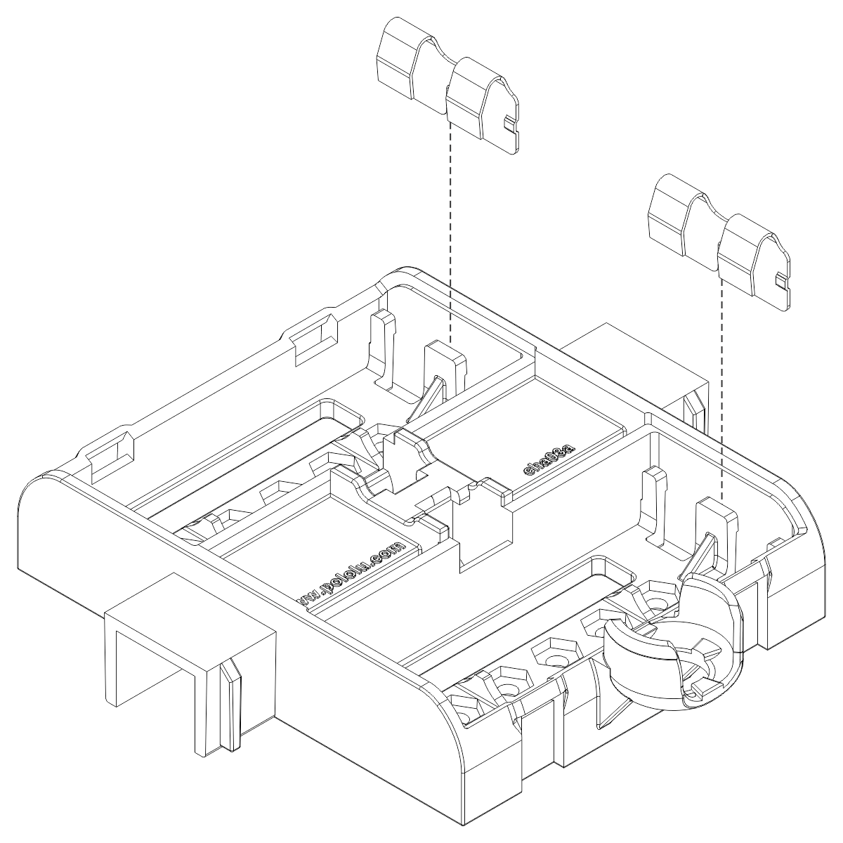
Battery contacts
- Insert the two double battery contacts into the bottom of the chassis as shown, making sure to put them on the correct side.
- Insert the four single battery contacts into the top of the chassis as shown. Adjust them until they are centered, straight, and match the height of the double battery contacts.
Motors and encoders
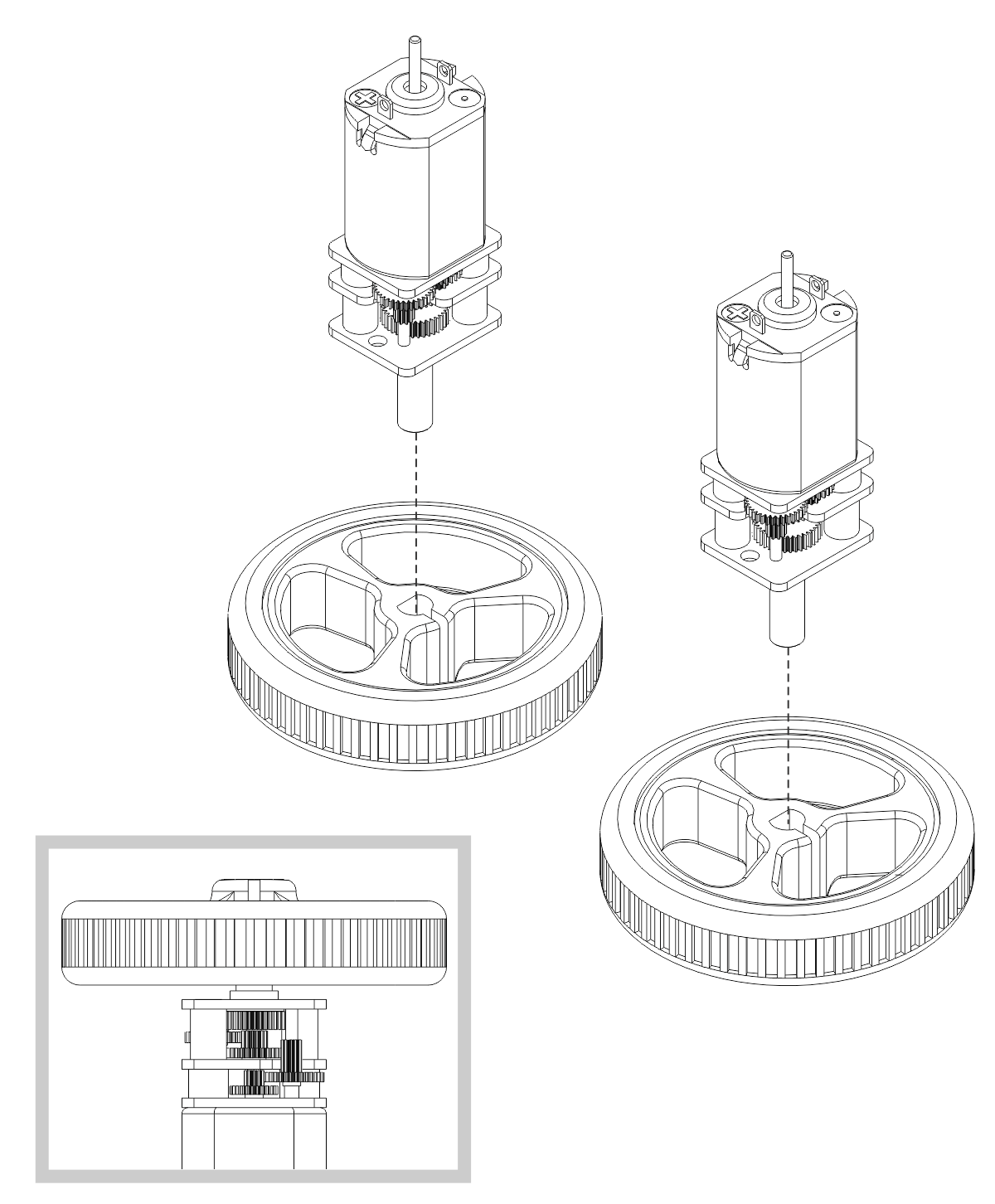
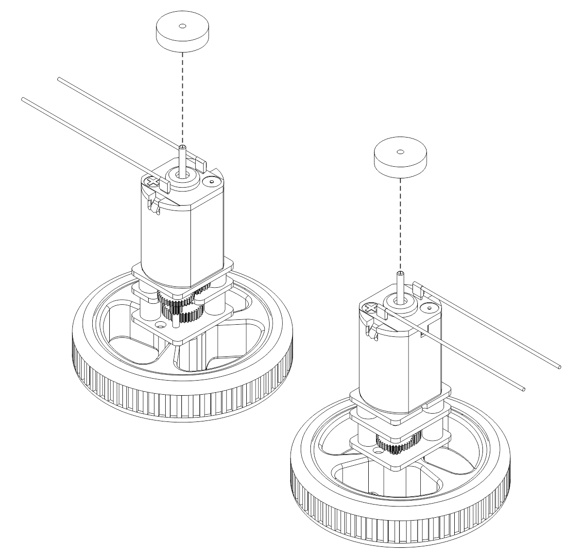
- After installing the tires on the wheels, press the output shaft of each motor into a wheel, with the flat side of the wheel hub facing the motor. The end of the gearbox shaft should end up flush with the outside of the wheel. A good way to do this is to set the wheel on a flat surface (like a table top) and press the motor shaft into the wheel until it contacts the surface.
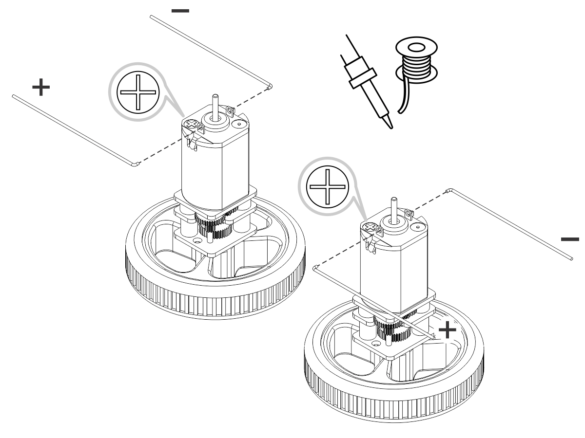
- Cut two of the included jumper wires in half to form four segments, and trim off the ends that are covered in adhesive (the adhesive could interfere with making a good electrical connection to the motor). These wire segments will be used as motor leads.
- Solder a pair of leads to each motor, paying attention to the way the motor will eventually be oriented in the chassis (see below). You might find it helpful to make a small bend at the tip of each lead to hook into the hole in the motor lead tab to hold it in place for soldering.
Warning: Holding the soldering iron against the motor lead for more than a few seconds can start to damage the motor brushes, so try to be reasonably quick/efficient with this soldering. If the first attempt does not go well, remove the soldering iron and let the motor cool for a few seconds before trying again.
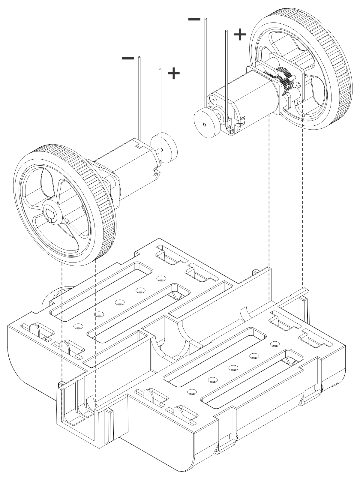
Each motor’s positive terminal is indicated by a plus sign (+) in the black plastic end of the motor. For consistency, we recommend soldering the motors to the control board with the positive terminal closest to the front, so you should attach the leads to allow the motors to be oriented this way. (Don’t worry if you accidentally get the orientation of one or both motors wrong, though. You can later correct for it in software with our Pololu3piPlus32U4 library.)
- Press a magnetic encoder disc onto the motor shaft of each motor so that the end of the shaft is flush with the back of the disc. One easy way to accomplish this is to press the motor onto the disc while the disc is sitting on a flat surface, pushing until the shaft makes contact with that surface.
- Place the motors into the channel in the middle of the chassis, aligning each gearbox with the grooves in the channel. The outer plate of the gearbox should be even with the edge of the chassis.
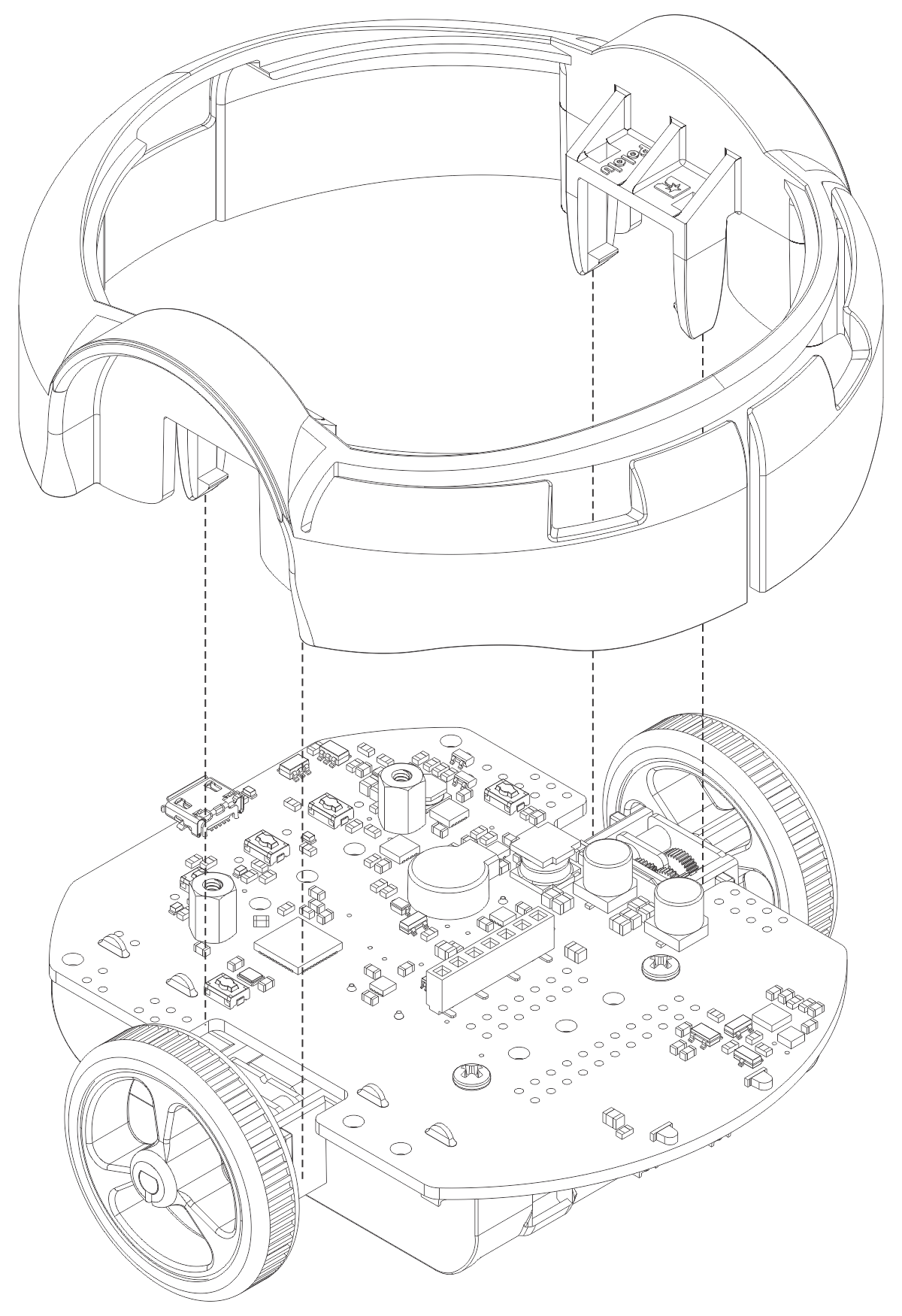
Control board and bumper skirt
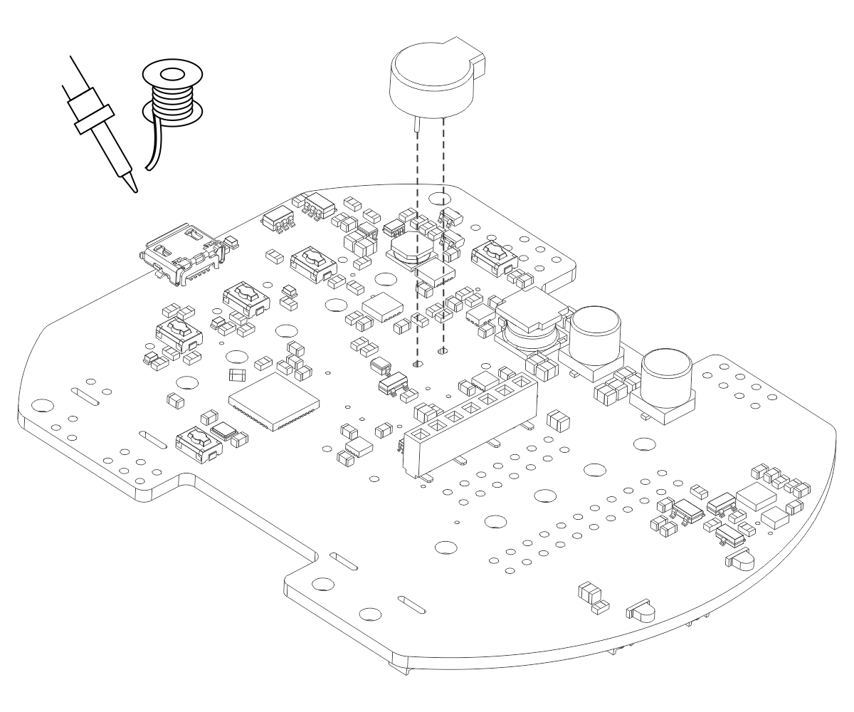
- Solder the buzzer to the 3pi+ 32U4 control board.
- Optional: This is a convenient time to add any other optional electronics or headers.
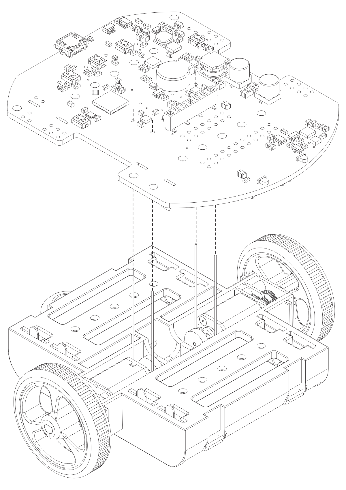
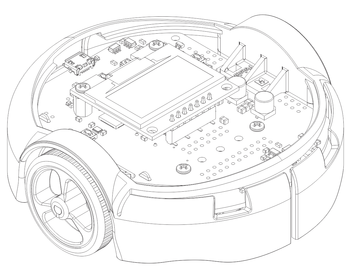
- Place the control board on the chassis. The motor leads and single battery contacts should be inserted into the corresponding through holes.
- Screw the control board to the chassis: we recommend using two screws in the outermost holes of the front row and two standoffs in the outermost holes of the back row. (For the original LCD version, which does not include standoffs, you can use screws in all four locations instead.) In each of the four mounting holes, insert a #2-56 machine screw or standoff through the main board and chassis, and tighten it against a nut under the chassis. It is usually easier to place the nut into the recess first and hold it there with a finger or piece of tape while inserting the screw or standoff.
- Trim off the excess length of wire from each motor lead.
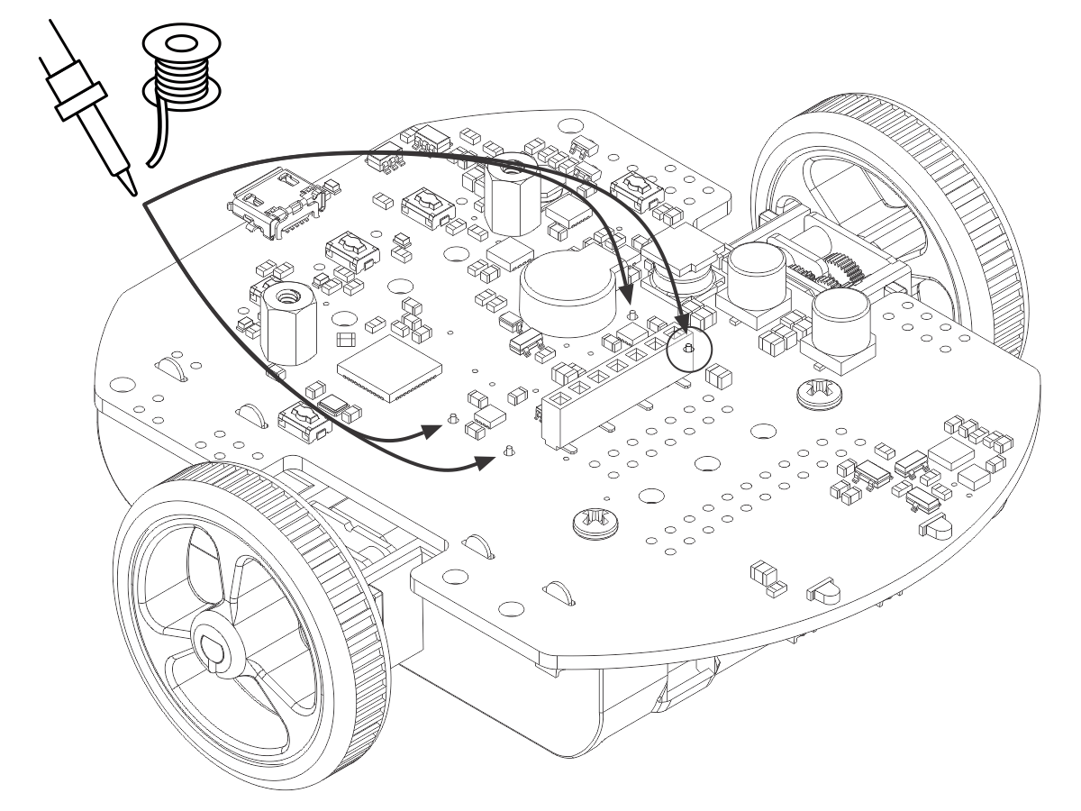
- Solder the motor leads to the main board.
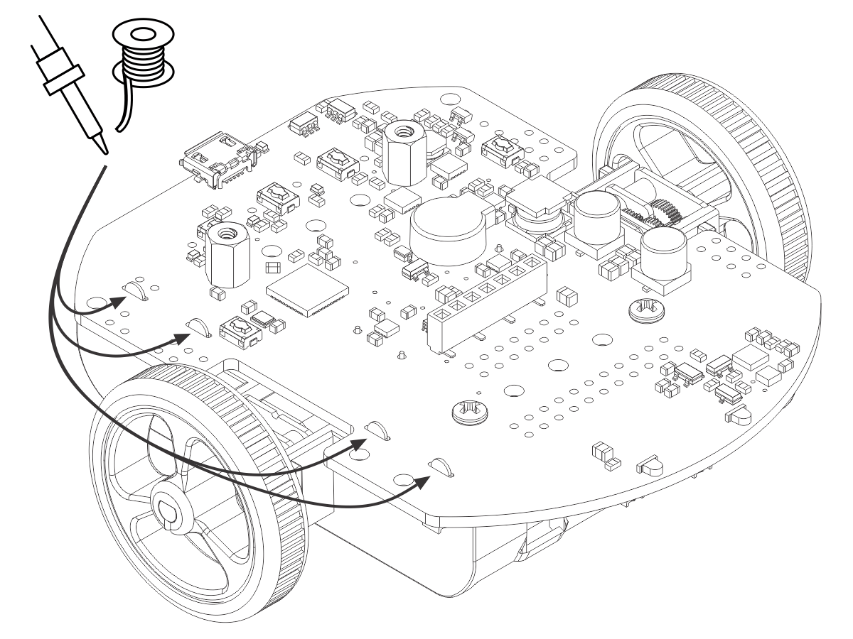
- Double-check the alignment of the battery contacts, then solder the single battery contacts to the main board.
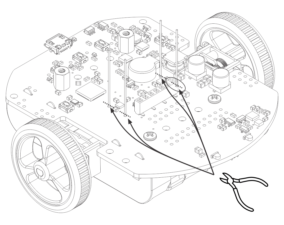
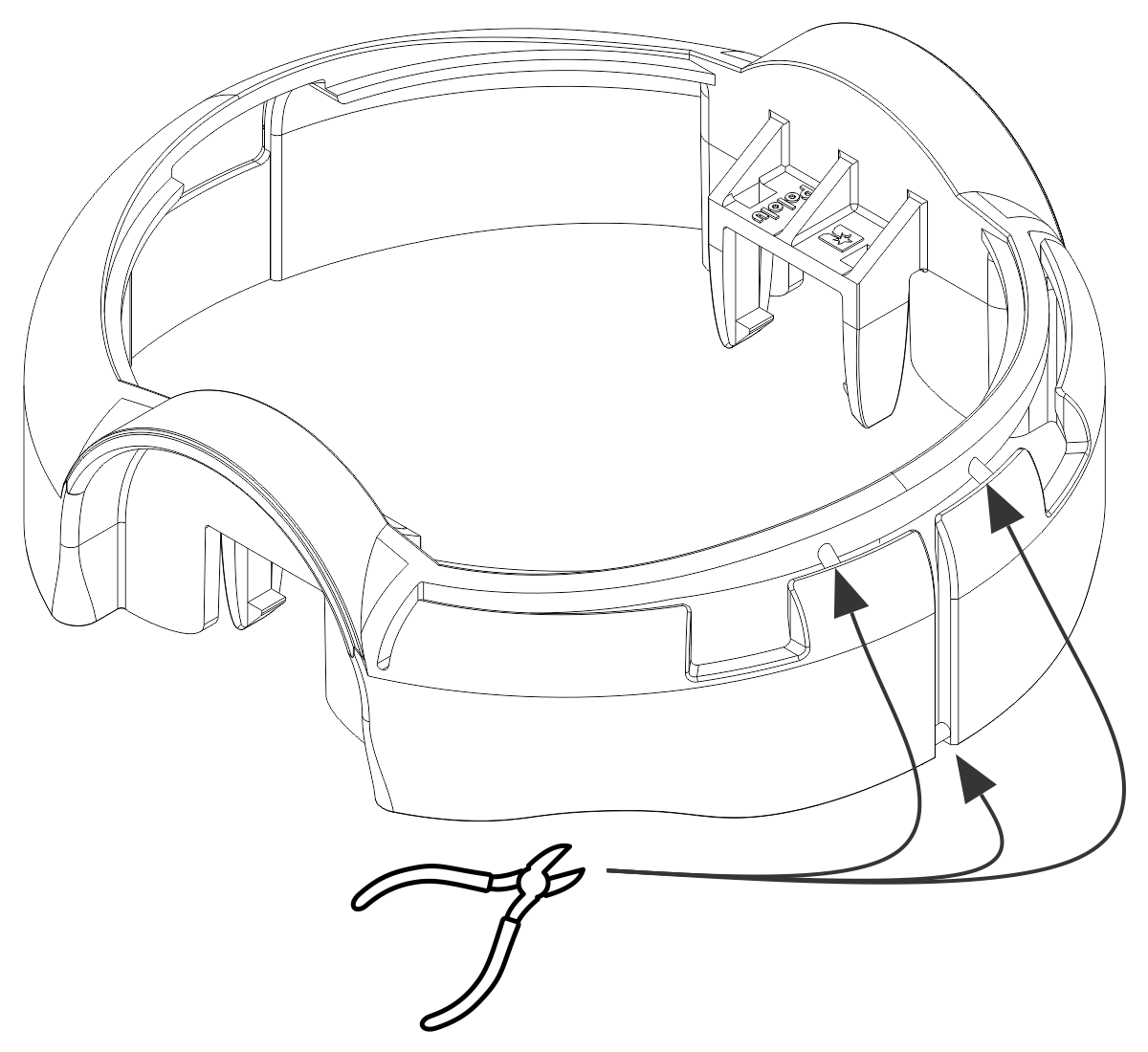
- Optional: We recommend cutting the supports for the flaps on the front of the bumper skirt, since the flaps need to be able to deflect for the bump sensors on the 3pi+ 32U4 to work. The easiest way to do this is with a pair of flush cutters, but you can also use diagonal cutters or a knife (which might leave behind bumps that you need to clean up with a file).
- Install the bumper skirt by pushing the clips on each side over the motor housings until they snap into place.
Display
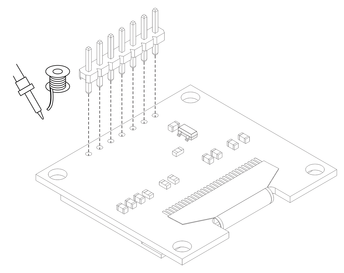
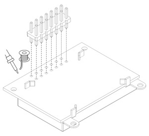
- Solder the 1×7 low-profile header to the OLED display (or the 2×7 low-profile header to the LCD). The shorter side of the header should be inserted fully through the corresponding through holes from the bottom side of the display module until the header is flush, and the solder joints should be made on the top (screen) side of the display. Tip: Solder a single pin first and ensure the header is flush before making any additional solder joints. If the header is not flush, you can use the soldering iron to re-melt the solder joint while you make the necessary adjustments. Be careful not to touch the pin you are soldering as the heat will conduct all the way through to the other end!
 | Installing header pins on the OLED display. |
|---|
|
 | Installing header pins on the LCD. |
|---|
|
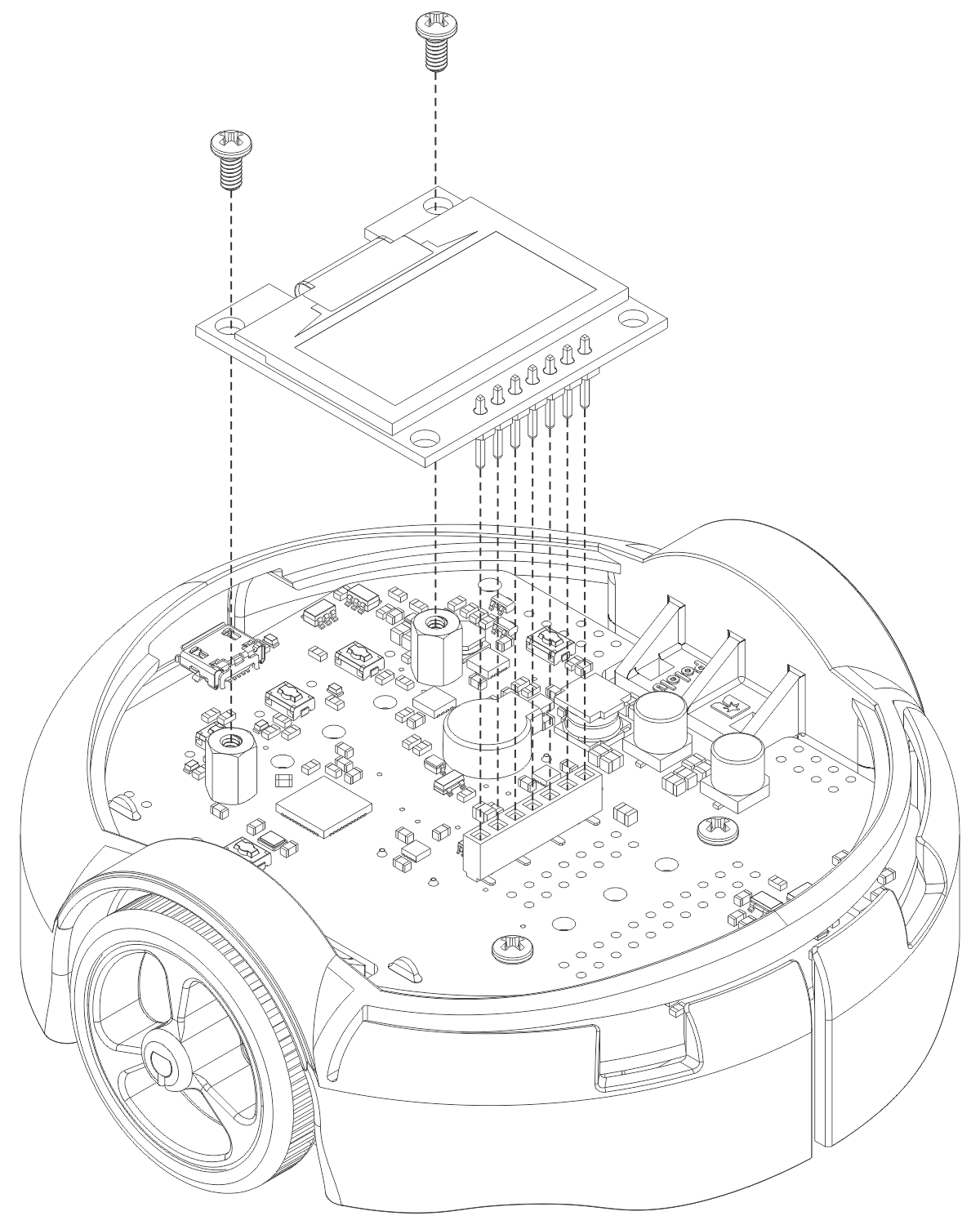
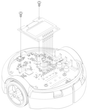
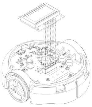
- Plug the display into the matching female header on top of the main board. You can optionally use two more #2-56 screws to secure the OLED display to the standoffs.
Warning: The display header does not enforce proper orientation, so it is possible to plug the display in offset or rotated 180° from its intended position. Incorrect positioning can damage the display or the control board, so please take care during this step to ensure that the display is plugged in properly.
 | Mounting the 3pi+ 32U4 OLED display. |
|---|
|
 | Mounting the 3pi+ 32U4 LCD. |
|---|
|
Ball caster and battery covers
- Press the ball caster into its socket on the bottom of the chassis.
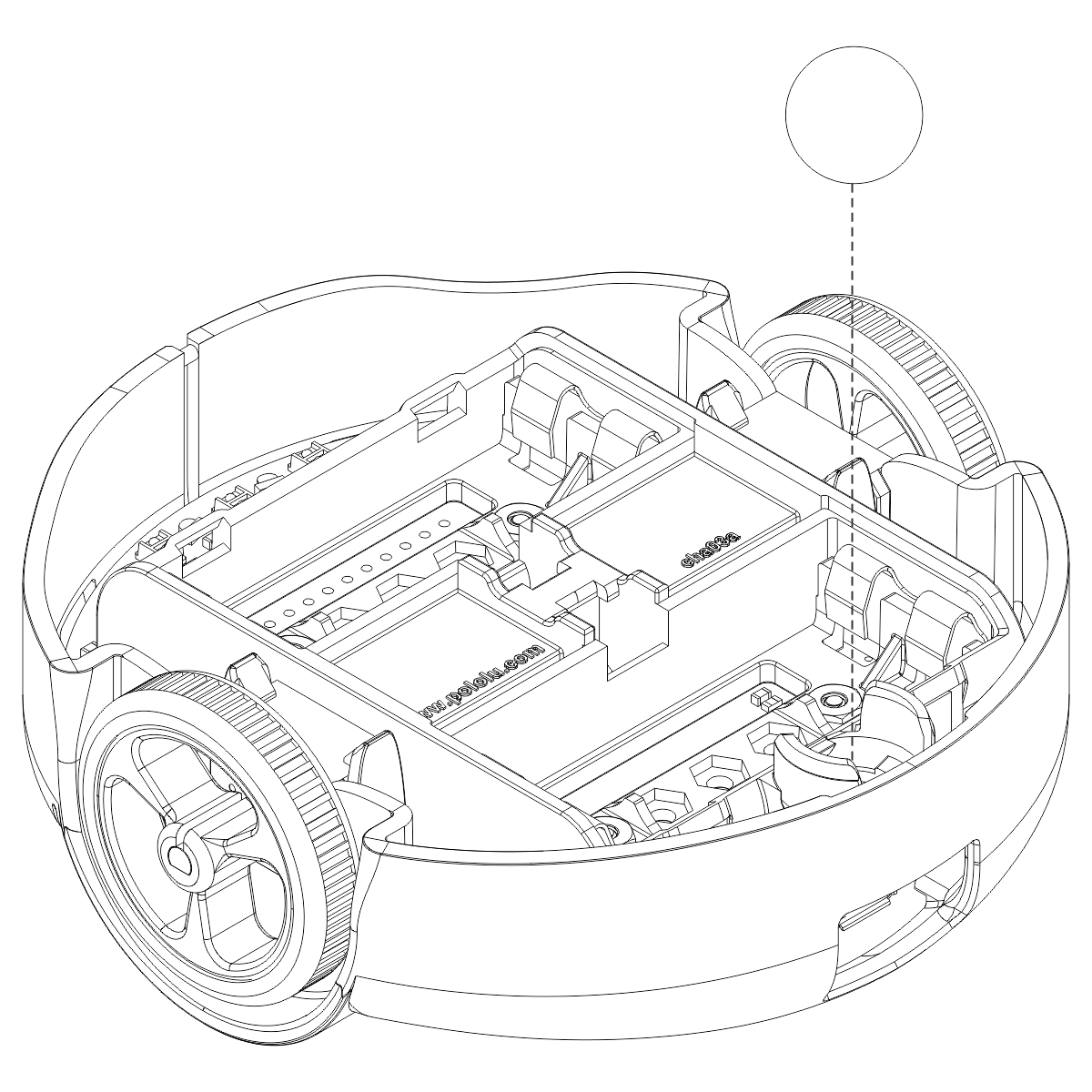
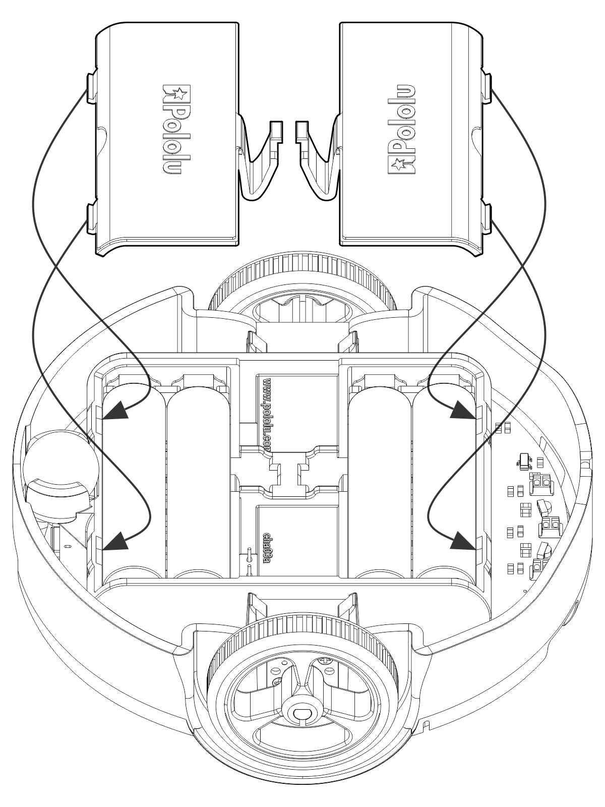
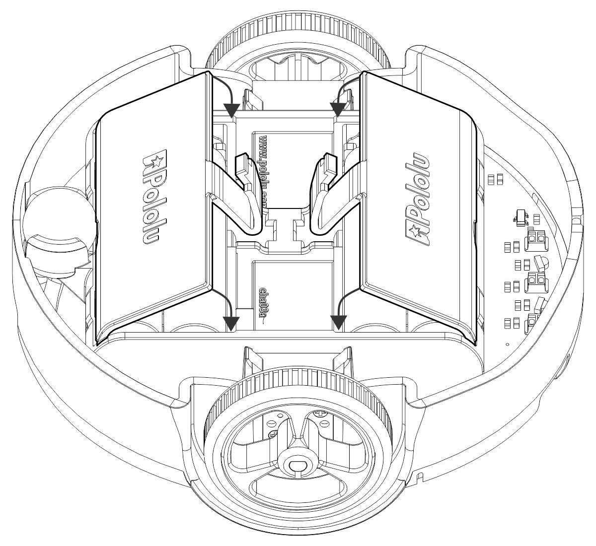
- Install four new or freshly charged AAA batteries in the battery compartment (we recommend using rechargeable AAA NiMH cells). The correct orientation for the batteries is indicated by the silkscreen markings printed on the bottom of the control board, visible through the slots in the chassis. Be careful not to reverse any of the batteries, or else the 3pi+ 32U4 will not operate properly (although the control board will not be damaged).
- Secure the battery compartment covers by first hooking their tabs into the corresponding slots at the outer edges of the battery compartments…
- …and then pivoting the covers down until the clips snap into place.
The assembly of your 3pi+ 32U4 robot is now complete, and it is ready to be used!