Support »
Pololu Dual TB9051FTG Motor Driver Shield User’s Guide

View document on multiple pages.
- 1. Overview
- 2. Contacting Pololu
- 3. Getting started with an Arduino
- 4. Using as a general-purpose motor driver
- 5. Schematic diagram
1. Overview
 |
Dual TB9051FTG Motor Driver Shield for Arduino. |
|---|
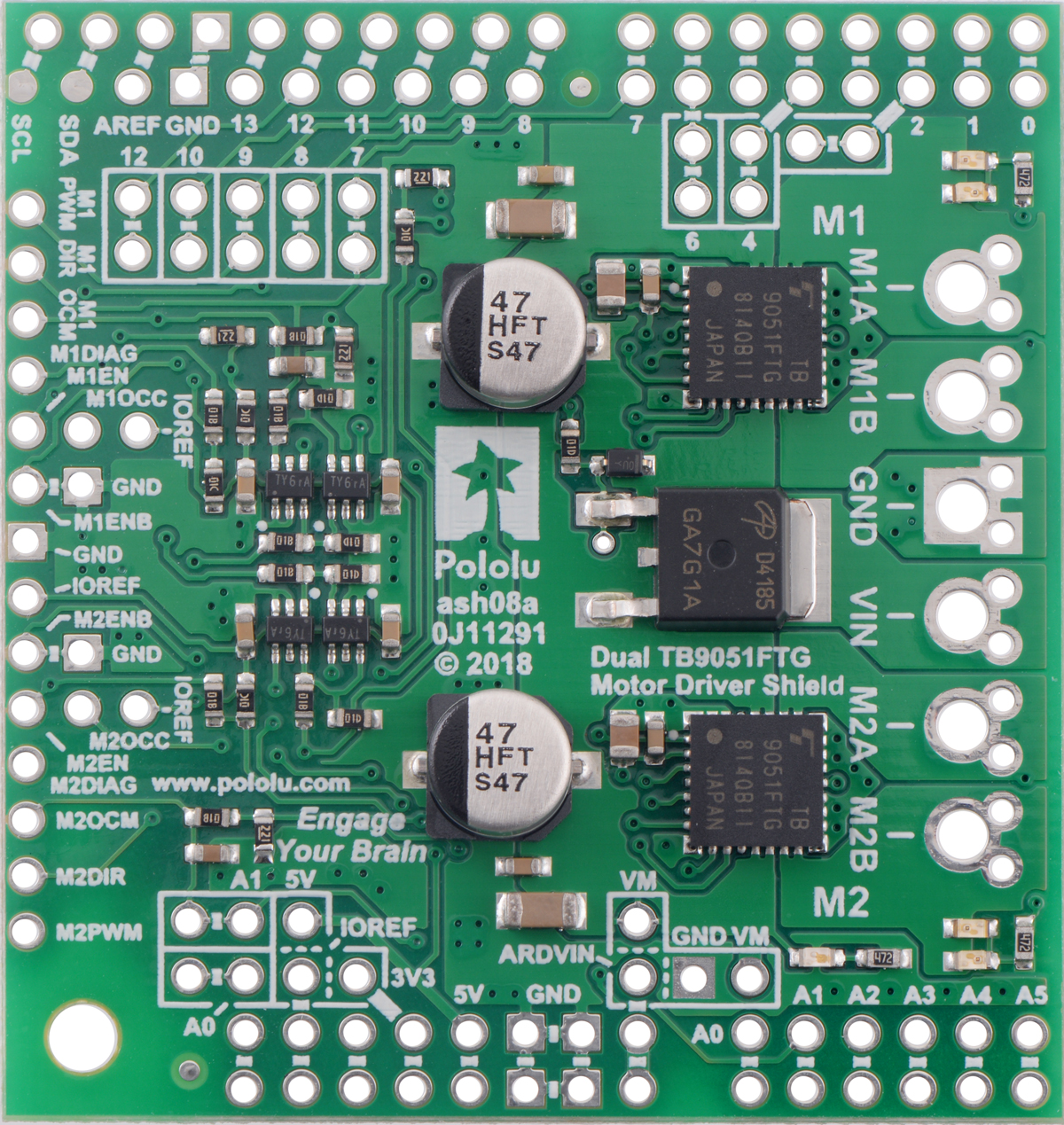
The Pololu dual TB9051FTG motor driver shield for Arduino and its corresponding Arduino library make it easy to control two bidirectional, brushed DC motors with an Arduino or compatible board, such as the A-Star 32U4 Prime. The board features a pair of Toshiba TB9051FTG motor drivers, which operate from 4.5 to 28 V and can deliver up to 2.6 A per channel continuously, and includes current sense circuitry, reverse battery protection, and logic gates to reduce the required number of I/O pins. The drivers automatically limit the peak current to around 5 A, which they can deliver for a few seconds in typical applications before the thermal protection activates. It ships fully populated with its SMD components, including the two TB9051 ICs, as shown in the picture to the right; stackable Arduino headers and terminal blocks for connecting motors and motor power are included but are not soldered in.
This versatile motor driver is intended for a wide range of users, from beginners who just want a plug-and-play motor control solution for their Arduinos (and are okay with a little soldering) to more advanced users who want a general-purpose dual-channel version of our single-channel TB9051FTG carrier to use with other microcontroller boards, outside of the Arduino environment. The Arduino pin mappings can all be customized if the defaults are not convenient, and the simplified TB9051FTG control lines are broken out along the left side of the board, providing a convenient interface point for other microcontroller boards.
1.a. Features
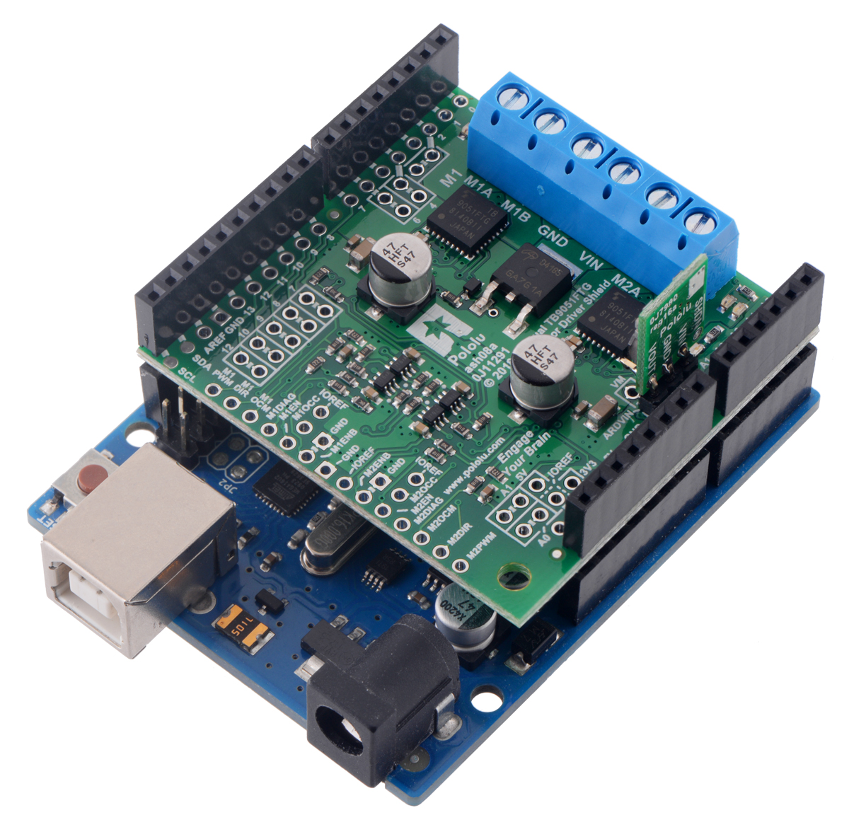 |
Dual TB9051FTG Motor Driver Shield on an Arduino Uno (with a regulator added to power the Arduino from the shield’s VIN). |
|---|
 |
 |
Dual TB9051FTG Motor Driver Shield for Arduino being controlled by an A-Star 32U4 Prime SV. |
|---|
- Dual-channel H-bridge motor driver in the form factor of an Arduino shield
- Wide operating voltage range: 4.5 V to 28 V
- Output current: up to 2.6 A continuous (5 A peak) per motor
- Automatic current chopping feature helps prevent overheating by gracefully reducing power rather than abruptly shutting down
- PWM operation up to 20 kHz, which is ultrasonic and allows for quieter motor operation
- Current sense voltage output proportional to motor current (approx. 500 mV/A; only active while H-bridge is driving)
- Motor indicator LEDs show what the outputs are doing even when no motor is connected
- Can be used with an Arduino or Arduino-compatible board (through the stackable shield headers) or with other microcontroller boards (through the 0.1″ header along the left side)
- When used as a shield, the motor power supply can optionally be used to power the Arduino base as well, either directly or through an added regulator like the D24V5F9 or S10V3F9
- Arduino pin mappings can be customized if the default mappings are not convenient
- Arduino library makes it easy to get started using this board as a motor driver shield
- Secondary access points for most Arduino pins, all on the same 0.1″ grid
- Exposed solderable ground pad below each driver IC on the bottom of the PCB
- Reverse-voltage protection on motor supply
- Robust drivers:
- Transient operation (< 500 ms) up to 40 V
- Under-voltage lockout and protection against over-current/short-circuit and over-temperature
- Active-low error outputs indicate over-current, over-temperature, under-voltage, or VCC over-voltage conditions for each driver
1.b. Included hardware
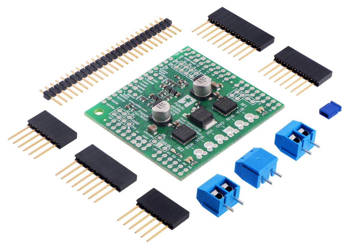 |
Dual TB9051FTG Motor Driver Shield for Arduino with included hardware. |
|---|
This motor driver board ships with all of the surface-mount parts populated. However, soldering is required for assembly of the included through-hole parts. The following through-hole parts are included:
- one extended/stackable 1×10 female header (for Arduino shields)
- two extended/stackable 1×8 female headers (for Arduino shields)
- two extended/stackable 1×6 female headers (for Arduino shields)
- three 2-pin, 5 mm terminal blocks (for board power and motor outputs)
- 25-pin 0.1″ straight breakaway male header
A 0.1″ shorting block (for optionally supplying shield power to Arduino) is also included.
The terminal blocks can be soldered into the larger holes to allow for convenient temporary connections of unterminated power and motor wires (see our short video on terminal block installation), or you can break off a 1×12 section of the 0.1″ header strip and solder it into the smaller through-holes that border these larger holes. Note, however, that each header pin is only rated for 3 A (there is a pair of pins for each connection), so for higher-power applications, the terminal blocks should be used or thick wires should be soldered directly to the board.
When not using this board as an Arduino shield, you can solder the pieces of the 0.1″ header to the logic connections along the left side of the board to enable use with custom cables or solderless breadboards, or you can solder wires directly to the board for more compact installations. Note that motor and motor power connections should not be made through a breadboard.
The mounting hole is intended for use with #4 screws (not included).
An Arduino is not included.
2. Contacting Pololu
|
Dual TB9051FTG Motor Driver Shield on an Arduino Uno (with a regulator added to power the Arduino from the shield’s VIN). |
|---|
We would be delighted to hear from you about any of your projects and about your experience with the dual TB9051FTG motor driver shield for Arduino. If you need technical support or have any feedback you would like to share, you can contact us directly or post on our forum. Tell us what we did well, what we could improve, what you would like to see in the future, or anything else you would like to say!
3. Getting started with an Arduino
As with virtually all other Arduino shields, connections between the Arduino and the motor driver are made via extended stackable headers that must be soldered to the through-holes along the top and bottom edges of the shield. This section explains how to use this motor driver as an Arduino shield to quickly and easily add control of up to two DC motors to your Arduino project. For information on how to use this board as a general-purpose motor driver controlled by something other than an Arduino, see Section 4.
3.a. What you will need
The following tools and components are required for getting started using this motor driver as an Arduino shield:
- An Arduino or compatible control board. Using this product as an Arduino shield (rather than a general-purpose motor driver board) requires an Arduino or an Arduino compatible board like our A-Star 32U4 Prime. This shield should work with all Arduinos and Arduino clones that behave like a standard Arduino. You will also need a USB cable for connecting your Arduino to a computer.
- A soldering iron and solder. The through-hole parts included with the shield must be soldered in before you can plug the shield into an Arduino or before you can connect power and motors. An inexpensive soldering iron will work, but you might consider investing in a higher-performance, adjustable soldering iron if you will be doing a lot of work with electronics.
- A power supply. You will need a power supply, such as a battery pack, capable of delivering the current your motors will draw. See the Power Connections and Considerations portion of Section 3.c for more information on selecting an appropriate power supply.
- One or two brushed DC motors. This shield is a dual motor driver, so it can independently control two bidirectional brushed DC motors. See the Motor Connections and Considerations portion of Section 3.c for more information on selecting appropriate motors.
3.b. Assembly for use as an Arduino shield
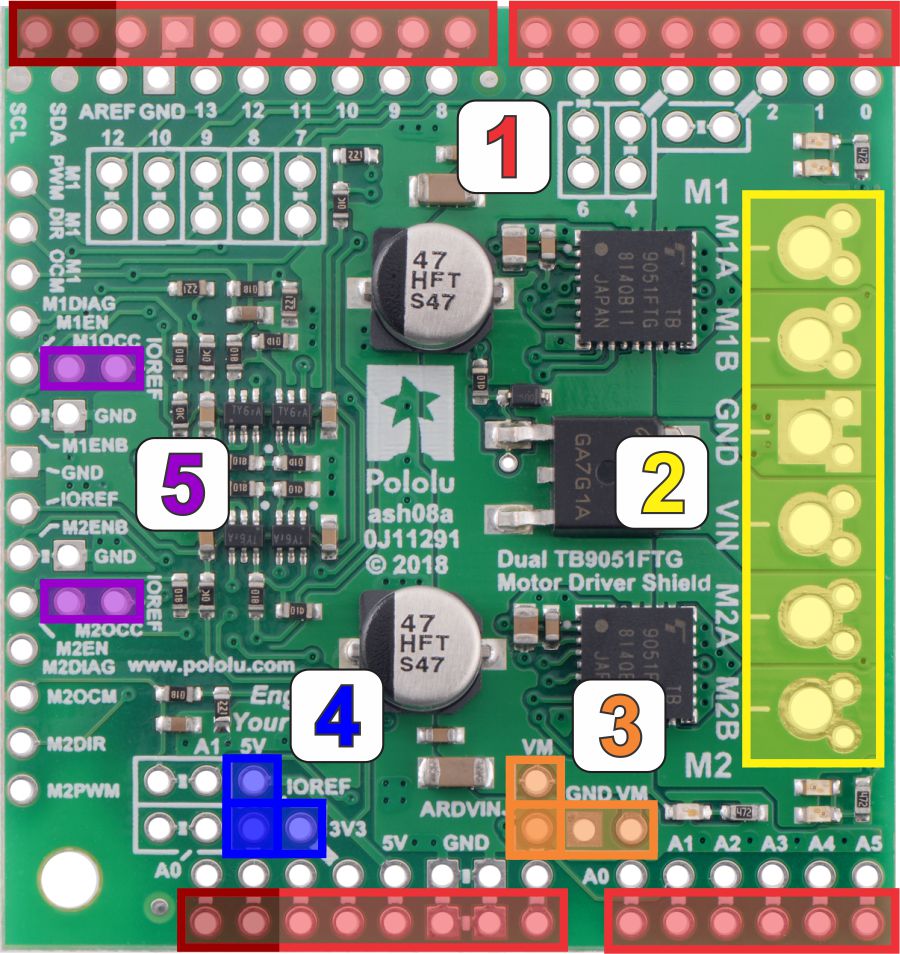 |
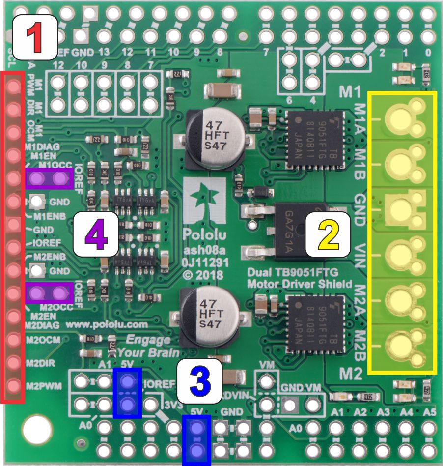
Stackable Arduino headers: Before you can use this board as an Arduino shield, you need to solder four of the five included Arduino header strips to the set of holes highlighted in red in the picture above. The headers should be oriented so that the female sockets rest on the top side of the shield and face up while the male pins protrude down through the board, and the solder connections should be made on the underside of the shield. Newer Arduino boards, including the Uno R3 and the Leonardo, use one 1×10 header, two 1×8 headers, and one 1×6 header, as shown in the picture to the right; older Arduino boards use two 1×8 headers and two 1×6 headers (the two pairs of pins highlighted in darker red above should not be populated if you are using this board with an older Arduino that does not support these additional pins). Please make sure you solder the appropriate headers for your particular Arduino!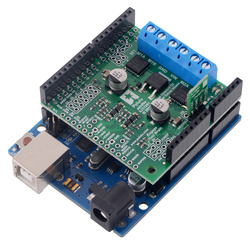
- Motor and power connections: The six large holes/twelve small holes on the right side of the board, highlighted in yellow in the above diagram, are the motor outputs and power inputs. You can optionally solder the included 5mm-pitch terminal blocks to the six large holes to enable temporary motor and motor power connections (see our short video on terminal block installation), or you can break off a 1×12 section of the included 0.1″ header strip and solder it into the smaller through-holes that border the six large motor and motor power pads. Note, however, that each header pin is only rated for 3 A (there is a pair of pins for each connection), so for higher-power applications, the terminal blocks should be used or thick wires with high-current connectors should be soldered directly to the board. The smaller holes are intended only for 0.1″ header pins, not for the terminal blocks!
- Arduino power jumper: If you want the option of powering your Arduino and motor shield from the same source, you can use the pins highlighted in orange in the picture above. If your motor power is within the required input voltage range for your Arduino, you can solder a 1×2 piece of the included 0.1″ male header strip to the two adjacent pins labeled VM and ARDVIN. Shorting across these pins with the included shorting block will connect the shield’s reverse-protected power, VM, to the Arduino’s VIN pin. You should not use this to power the shield from the Arduino as this connection is not designed to handle high currents, and you must never supply power to the Arduino’s VIN pin or power jack while this shorting block is in place, because it will create a short between the shield power supply and the Arduino power supply and will likely permanently damage something.
Alternatively, if your motor power is not within the voltage range required for your Arduino, but you would still like to use it to power your Arduino, you can connect a regulator to the 3 pins labeled ARDVIN, GND, and VM (also highlighted in orange) to provide a regulated voltage to the Arduino. Never supply power to the Arduino’s VIN pin or power jack when powering your Arduino this way, because it will create a short between the regulator’s output voltage and the Arduino power supply and will likely permanently damage something. - Logic voltage: The shield uses the voltage from the Arduino’s IOREF pin for its logic voltage. If your Arduino doesn’t have an IOREF pin, connect the IOREF pin highlighted in blue in the picture above to either the adjacent 5V or 3V3 pin, whichever one corresponds to your Arduino’s logic voltage. You can use a 1×2 piece of the included 0.1″ male header strip and a shorting block to do this.
- M1OCC and M2OCC to IOREF: The M1OCC and M2OCC pins set the drivers’ over-current response. By default, the drivers remain disabled after an over-current condition, but if the OCC pins are high, they automatically try to resume driving after a short delay instead. You can use the pins highlighted in purple to short the M1OCC and M2OCC pins to the IOREF voltage using a 1×2 piece of the included 0.1″ male header strip and a shorting block.
3.c. Shield connections: signals, power, and motors
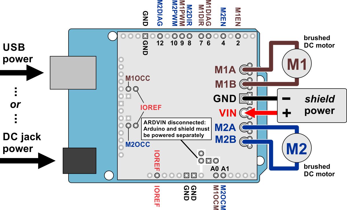 |
Using the dual TB9051FTG motor driver shield with an Arduino (shield and Arduino powered separately). |
|---|
All of the necessary logic connections between the Arduino and the motor driver shield, including VCC, are made automatically when the shield is plugged into the Arduino. However, the shield’s motor power must be supplied directly to the shield itself via its large, high-current VIN and GND pads. The motor channels, located on either side of these power pins, can each be used to independently control a bidirectional brushed DC motor. Each motor channel is comprised of a pair of pins—MxA and MxB—that connect to the two terminals of a DC motor and can deliver a continuous 2.6 A (5 A peak). The picture above shows the typical connections involved in using this board as an Arduino shield. In the depicted configuration, the Arduino is powered separately from the shield, such as through its USB connector or power jack.
Default Arduino pin mappings
The following table shows how the shield connects your Arduino’s pins to the motor drivers’ pins:
| Arduino Pin | Shield Pin Name | Basic Function |
|---|---|---|
| Digital 2 | M1EN | Enable input: when EN is low, M1A and M1B are set to high impedance. The board pulls this pin up to IOREF, enabling the driver by default. |
| Digital 4 | M2EN | Enable input: when EN is low, M2A and M2B are set to high impedance. The board pulls this pin up to IOREF, enabling the driver by default. |
| Digital 6 | M1DIAG | Motor 1 diagnostic error output: driven low when certain faults have occurred or when the driver is disabled by the EN input. Otherwise, the board pulls this pin up to IOREF. |
| Digital 7 | M1DIR | Motor 1 direction input |
| Digital 8 | M2DIR | Motor 2 direction input |
| Digital 9 | M1PWM | Motor 1 speed input |
| Digital 10 | M2PWM | Motor 2 speed input |
| Digital 12 | M2DIAG | Motor 2 diagnostic error output: driven low when certain faults have occurred or when the driver is disabled by the EN input. Otherwise, the board pulls this pin up to IOREF. |
| Analog 0 | M1OCM | Motor 1 current monitor output (approximately 500 mV/A per amp) |
| Analog 1 | M2OCM | Motor 2 current monitor output (approximately 500 mV/A per amp) |
See Section 4.b for more detailed descriptions of the shield pins, Section 4.c for a motor control truth table, and Section 5 for a schematic diagram of the shield. See Section 3.e for instructions on how to customize your board’s Arduino pin mappings if the above defaults are not convenient.
Power connections
 |
Dual TB9051FTG motor driver shield power buses. |
|---|
In the shield’s default state, the motor driver shield and Arduino are powered separately. When used this way, the Arduino must be powered via USB, its power jack, or its VIN pin, and the shield must be supplied with 4.5 to 28 V through the large VIN and GND pads on the right side of the board. Attempting to power the shield through other means, such as from the Arduino or through the small VOUT pin, can permanently damage both the Arduino and the shield (only the large power traces on the right side of the shield are designed to handle the high currents involved in powering motors). A high-side reverse-voltage protection MOSFET prevents the shield from being damaged if motor power is inadvertently connected backwards. Logic power, VCC, is automatically supplied by the Arduino.
 |
Using the dual TB9051FTG motor driver shield with an Arduino (Arduino powered by shield). |
|---|
It is also possible to power your Arduino directly from the motor shield, which eliminates the need for a separate Arduino power supply. If the motor power is within the acceptable input voltage range for your Arduino, you can place a shorting block across the pins labeled VM and ARDVIN to provide the shield’s reverse-protected power, VM, to the Arduino’s VIN pin, as shown in the diagram above. The Arduino’s power jack must remain disconnected at all times in this configuration.
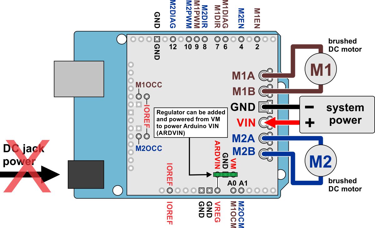 |
Using the dual TB9051FTG motor driver shield with an Arduino (Arduino powered by external regulated connected to shield). |
|---|
If your motor power is not within the acceptable input voltage range but you would still like to use it to power your Arduino, you can use the pins labeled ARDVIN, GND, and VM to connect a regulator like the D24V5F9 or S10V3F9 between the motor power and the Arduino’s VIN, as seen in the diagram above. The Arduino’s power jack must remain disconnected at all times in this configuration.
Warning: When powering the Arduino from the motor shield using either the shorting block or a regulator, you must never connect a different power supply to the Arduino’s VIN pin or plug a power supply into the Arduino’s power jack, as doing so will create a short between the Arduino’s power supply and either the shield’s power supply or your regulator that could permanently damage the Arduino and the motor shield or regulator.
Note that the ARDVIN pin on the shield just goes to the Arduino’s VIN pin, so plugging in USB when powering the Arduino through this pin is just like plugging in USB with the Arduino powered from its power jack. On standard Arduinos we recommend against plugging a powered Arduino into USB (see this forum post for more information), but on some Arduino-compatible boards such as the A-Stars, this is completely safe.
Power considerations
The shield operates from 5 to 28 V, but it can tolerate transient voltages (shorter than 500 ms in duration) of up to 40 V, which means it is generally safe to power this board with a 24 V battery. The shield operating voltage range is much wider than the typical Arduino operating voltage range, so if you are using the shield to power your Arduino, please ensure that your voltage source is within acceptable limits for your Arduino or use a regulator between the motor power and the Arduino as described above.
It is important that you use a power source that is capable of delivering the current your motors will require. For example, alkaline cells are typically poor choices for high-current applications, and you should almost never use a 9V battery (the rectangular type with both terminals on the same side) as your motor power supply. We recommend NiMH batteries, lithium-based rechargeable batteries (if you have a good charger and adequately understand the dangers of using them improperly), or a power adapter with an appropriate power rating. The current draw is ultimately a function of your motors, your operating voltage, and your motor load, but the driver is capable of delivering a continuous 5.2 A (2.6 A per channel), and it can deliver in excess of 10 A before the internal current limiting is activated.
Shield power dissipation
The TB9051FTG will start chopping its output current at a typical threshold of 6.5 A. However, the chip by itself will typically overheat at lower currents. In our tests, we found that the chip was able to deliver 5 A for only a few seconds before the chip’s thermal protection kicked in; a continuous current of about 2.6 A per channel was sustainable for many minutes without triggering thermal current limiting or an over-temperature shutdown. The actual current you can deliver will depend on how well you can keep the motor driver cool. The shield’s printed circuit board is designed to help with this by drawing heat out of the motor driver chip. PWMing the motor will introduce additional heating proportional to the frequency.
Unlike typical H-Bridges, the TB9051FTG has a feature that allows it to gracefully reduce the maximum current limit when the chip temperature approaches its limit. This means that if you push the chip close to its limit, you will see less power to the motor, but it might allow you to avoid a complete shutdown.
This product can get hot enough to burn you long before the chip overheats. Take care when handling this product and other components connected to it.
Motor considerations
If your motor has a stall current over the driver’s continuous current rating of 2.6 A per channel, we recommend you take extra steps to make sure that your motor will not be exposed to loads that will cause it to exceed 2.6 A for prolonged periods of time (or you take extra steps to keep the motor drivers cool, such as increasing air flow or adding heat sinks). Exceeding 2.6 A for long durations should not damage the shield, but it will eventually activate the driver’s thermal protection, which might result in inadequate performance for your application.
It is not unusual for the stall current of a motor to be an order of magnitude (10×) higher than its free-run current. If you do not know your motor’s stall current, you can approximate it by measuring the current it draws while held stalled at a lower voltage (such as when powered from a single battery cell) and then scaling that value linearly with voltage. For example, the stall current of a motor at 6 V is six times the stall current of that motor at 1 V. Another, less accurate method is to use a multimeter to measure the resistance between the motor terminals and then use Ohm’s law to compute the stall current I at voltage V: I = V/R. This last method generally is not as reliable because it can be difficult to measure such small resistances accurately.
Occasionally, electrical noise from a motor can interfere with the rest of the system. This can depend on a number of factors, including the power supply, system wiring, and the quality of the motor. If you notice parts of your system behaving strangely when the motor is active, first double-check that your power supply is adequate, then consider taking the following steps to decrease the impact of motor-induced electrical noise on the rest of your system:
|
||
|
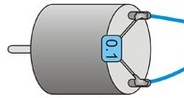
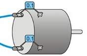
- Solder a 0.1 µF ceramic capacitor across the terminals of your motors, or solder one capacitor from each terminal to the motor case (see the pictures to the right). For the greatest noise suppression, you can use three capacitors per motor (one across the terminals and one from each terminal to the case).
- Make your motor leads as thick and as short as possible, and twist them around each other. It is also beneficial to do this with your power supply leads.
- Route your motor and power leads away from your logic connections if possible.
- Place decoupling capacitors (also known as “bypass capacitors”) across power and ground near any electronics you want to isolate from noise. These can typically range from 10 uF to a few hundred uF.
3.d. Programming your Arduino
Our Arduino library for the dual TB9051FTG motor driver shield makes it easy to get started writing your Arduino sketches. A link to download the library, installation instructions, and the library command reference can be found on the library’s github page or you can download the library from within the Arduino IDE by going to Sketch > Include Library > Manage Libraries… and then searching for DualTB9051FTGMotorShield, selecting the library, and then selecting Install.
Once installed, we recommend you try out the example sketch by selecting File > Examples > DualTB9051FTGMotorShield > Demo from the Arduino IDE, or by copying the following code into a new sketch:
#include "DualTB9051FTGMotorShield.h"

DualTB9051FTGMotorShield md;

void stopIfFault()
{
  if (md.getM1Fault())
  {
    Serial.println("M1 fault");
    while (1);
  }
  if (md.getM2Fault())
  {
    Serial.println("M2 fault");
    while (1);
  }
}

void setup()
{
  Serial.begin(115200);
  Serial.println("Dual TB9051FTG Motor Shield");
  md.init();

  // Uncomment to flip a motor's direction:
  //md.flipM1(true);
  //md.flipM2(true);
}

void loop()
{
  md.enableDrivers();
  delay(1); // wait for drivers to be enabled so fault pins are no longer low

  for (int i = 0; i <= 400; i++)
  {
    md.setM1Speed(i);
    stopIfFault();
    if (abs(i)%200 == 100)
    {
      Serial.print("M1 current: ");
      Serial.println(md.getM1CurrentMilliamps());
    }
    delay(2);
  }

  for (int i = 400; i >= -400; i--)
  {
    md.setM1Speed(i);
    stopIfFault();
    if (abs(i)%200 == 100)
    {
      Serial.print("M1 current: ");
      Serial.println(md.getM1CurrentMilliamps());
    }
    delay(2);
  }

  for (int i = -400; i <= 0; i++)
  {
    md.setM1Speed(i);
    stopIfFault();
    if (abs(i)%200 == 100)
    {
      Serial.print("M1 current: ");
      Serial.println(md.getM1CurrentMilliamps());
    }
    delay(2);
  }

  for (int i = 0; i <= 400; i++)
  {
    md.setM2Speed(i);
    stopIfFault();
    if (abs(i)%200 == 100)
    {
      Serial.print("M2 current: ");
      Serial.println(md.getM2CurrentMilliamps());
    }
    delay(2);
  }

  for (int i = 400; i >= -400; i--)
  {
    md.setM2Speed(i);
    stopIfFault();
    if (abs(i)%200 == 100)
    {
      Serial.print("M2 current: ");
      Serial.println(md.getM2CurrentMilliamps());
    }
    delay(2);
  }

  for (int i = -400; i <= 0; i++)
  {
    md.setM2Speed(i);
    stopIfFault();
    if (abs(i)%200 == 100)
    {
      Serial.print("M2 current: ");
      Serial.println(md.getM2CurrentMilliamps());
    }
    delay(2);
  }

  md.disableDrivers();
  delay(500);
}
This example ramps motor 1 speed from zero to max speed forward, to max speed reverse, and back to zero again over a period of about 3 s, while checking for motor faults and periodically printing the motor current to the serial monitor. It then performs the same process on motor 2 before repeating all over again.
Note: Even if you do not have any motors yet, you can still try out this sketch and use the motor indicator LEDs for feedback that the shield is working properly.
3.e. Remapping the Arduino connections
For some applications, this shield’s default Arduino pin mappings might not be convenient. For example, maybe you want to use the 16-bit Timer 1 for making music on a buzzer and would rather use PWMs from Timer 0 to control your motor speed. Or maybe you don’t care about monitoring the motor current and would rather use all of your analog inputs for reading sensors. With this in mind, we designed the shield to have break points in the connection between the Arduino pins and the motor drivers. It is easy to cut the connections at these points and establish new connections to replace the broken ones if desired.
The connections between the Arduino pins and the motor driver pins are each made through a pair of 0.1″-spaced holes that are connected on the top side of the shield by a thin trace. The following two diagrams show the default pin mapping for motor drivers 1 and 2:
|
|
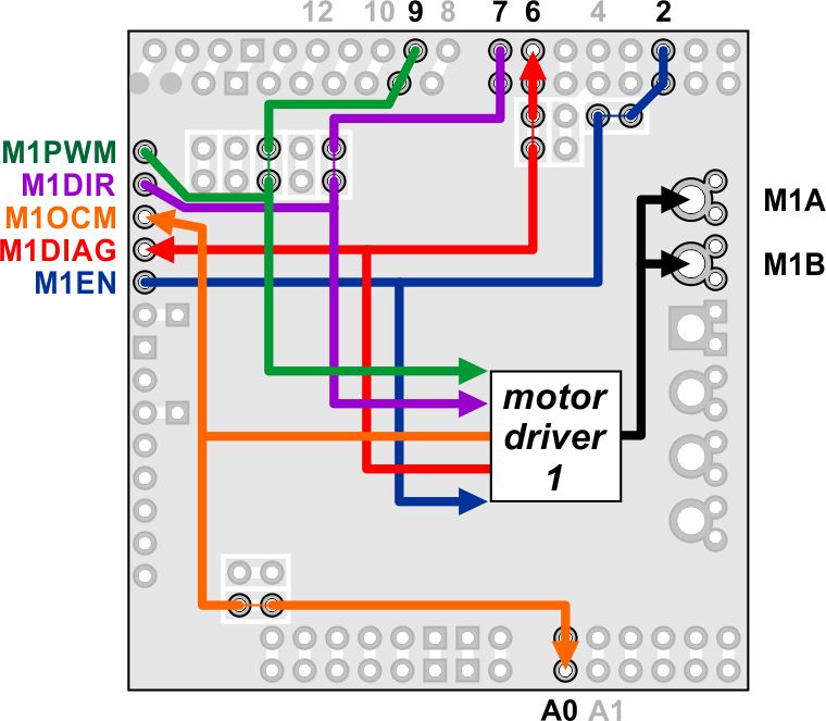
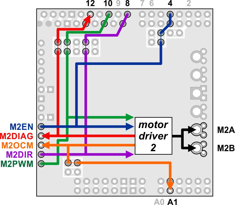
In all cases, the top through-holes of the vertical pairs and the right through-holes of the horizontal pairs connect to the Arduino pin, and the bottom/right through-holes connect to the motor driver pin. To change one of the default mappings, you can use a knife to cut the trace between the appropriate pair of holes on the top side of the PCB (there is no connection to cut on the underside of the PCB) and run a wire from a different Arduino pin to the bottom hole of the pair to create a new connection.
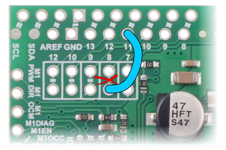 |
Dual TB9051FTG motor driver shield remapping example: moving M2DIR from Arduino pin 8 to pin 11. |
|---|
You can later use shorting blocks to restore the default pin mapping if you populate the severed hole pairs with 1×2 pieces of the included 0.1″ male header strip.
4. Using as a general-purpose motor driver
TB9051FTG motor driver control lines and output signals are available via the set of pins along the left side of the board, which means this shield can be used as a general-purpose motor driver controlled by devices other than Arduinos. This section explains how to use the dual TB9051FTG motor driver shield this way and provides some basic information about the motor driver pins to help get you started. We also encourage you to consult the TB9051FTG datasheet (2MB pdf) for detailed pin descriptions, truth tables, and electrical characteristics. This shield is essentially a breakout board for two TB9051FTG motor driver ICs with additional logic circuitry to simplify the motor control, so the datasheet is your best resource for answering questions not covered by this user’s guide.
4.a. Assembly for use as a general-purpose motor driver
 |
- Logic connections: The 14 small holes along the left side of the board, highlighted in red in the above diagram, are used to interface with the motor drivers. You can optionally solder a 1×14 piece of the included 0.1″ male header strip to these pins. Soldering the pins so they protrude down allows the logic side of the motor driver to be plugged into a standard solderless breadboard or perfboard. You can also solder 0.1″ female headers or custom connectors to these pins.
- Motor and power connections: The six large holes/twelve small holes on the right side of the board, highlighted in yellow in the above diagram, are the motor outputs and power inputs. You can optionally solder the included 5mm-pitch terminal blocks to the board to enable temporary motor and motor power connections, or you can break off an 1×12 section of the included 0.1″ header strip and solder it into the smaller through-holes that border the six large motor and motor power pads. Note, however, that each header pin pair is only rated for a combined 6 A, so for higher-power applications, the terminal blocks should be used or thick wires with high-current connectors should be soldered directly to the board.
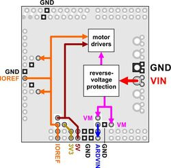
Dual TB9051FTG motor driver shield power buses.
- Logic power: The TB9051FTG drivers require 5 V but can accept logic signals from 3.3 V microcontrollers. Power needs to be applied to both the shield’s 5 V bus and the IOREF bus, which is used for the pullups on the board and should match your microcontroller’s power source (see the diagram to the right). There are several ways to do this.
- If your microcontroller uses 5 V, you can either:
- Connect 5 V to both the 5V pin highlighted in blue in the above diagram and the IOREF pin highlighted in red.
- Short together the pins labeled 5V and IOREF highlighted in blue (such as with a 1×2 male header strip and shorting block) and then connect 5 V to either of the two pins.
- If your microcontroller doesn’t use 5 V:
- Connect 5 V to the 5V pin and your microcontroller logic voltage to the IOREF pin.
- If your microcontroller uses 5 V, you can either:
- M1OCC and M2OCC to IOREF: The M1OCC and M2OCC pins set the drivers’ over-current response. By default, the drivers remain disabled after an over-current condition, but if the OCC pins are high, they automatically try to resume driving after a short delay instead. You can optionally solder a wire or a 1×2 piece of the included 0.1″ male header and install a shorting block to short the M1OCC and M2OCC pins to the IOREF voltage.
4.b. Board connections
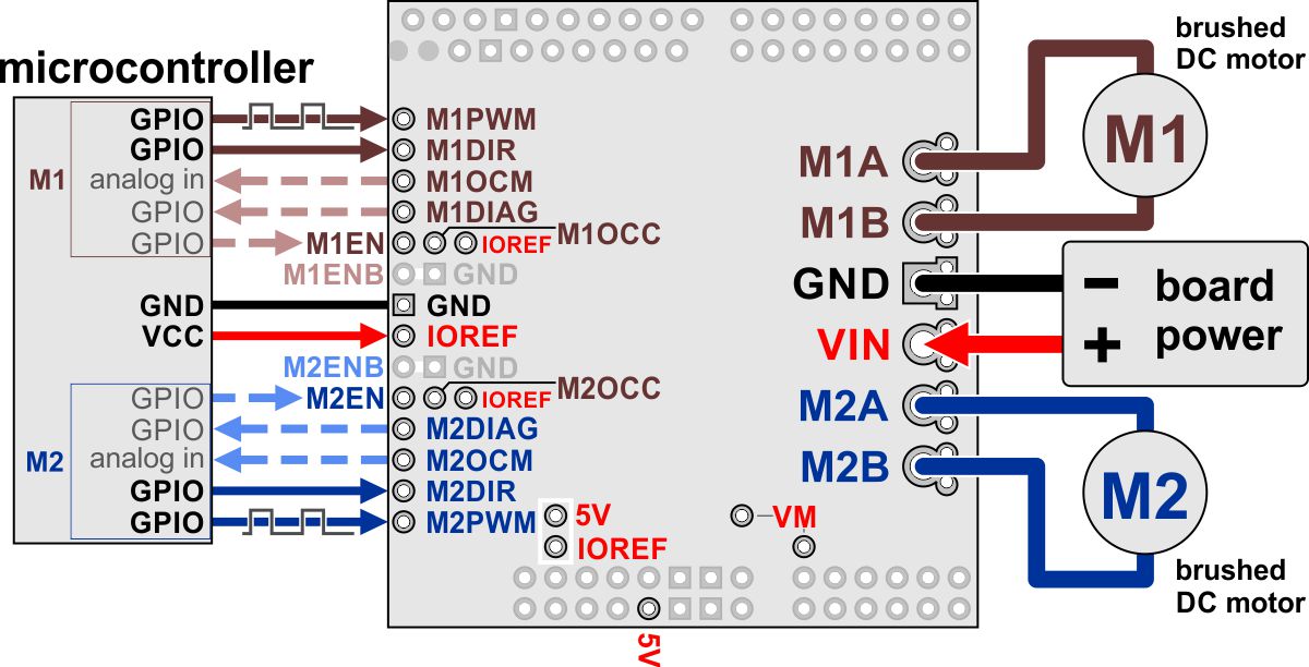 |
Using the dual TB9051FTG motor driver shield with a microcontroller. |
|---|
The above diagram shows the connections typically required to interface this motor driver with a microcontroller.
Pinout
| PIN | Default State | Description |
|---|---|---|
| VIN | Reverse-protected 4.5 V to 28 V board power supply input. | |
| GND | Ground connection points for the motor and logic supplies. The control source and the motor driver must share a common ground. | |
| VM | These pins give access to the motor power supply after the reverse-voltage protection MOSFET (see the board schematic below). They can be used to supply reverse-protected power to other components in the system. VM is generally intended as an output, but it can also be used to supply board power. | |
| 5V | 5 V input. Connected to the TB9051FTG drivers’ VCC pins. | |
| IOREF | Logic supply input. Connect to your microcontroller’s logic voltage. While the TB9051FTG IC does require a 5 V supply to operate, it can accept 3.3 V logic signals. | |
| MxA/B | Output of half-bridge A/B. Each half-bridge connects to one terminal of a DC motor. | |
| MxPWM | LOW | Motor speed inputs: A PWM (pulse-width modulation) signal on these pins corresponds to a PWM output on the corresponding channel’s motor outputs. When a PWM pin is low, the corresponding motor brakes low (both A and B are shorted together through ground). When it is high, the motor is on. The maximum allowed PWM frequency is 20 kHz. |
| MxDIR | LOW | Motor direction inputs: When DIR is high, motor current flows from output A to output B; when DIR is low, current flows from B to A. |
| MxOCM | Current monitor output: this pin provides an analog current-sense feedback voltage of approximately 500 mV per amp (only active while H-bridge is driving) through an on-board RC filter. | |
| MxDIAG | HIGH | Diagnostic error output: driven low when certain faults have occurred or when the driver is disabled by the EN or ENB inputs. Otherwise, the board pulls this pin up to IOREF. |
| MxOCC | LOW | Over-current response configuration input: by default, the driver remains disabled after an over-current condition, but if OCC is high, it automatically tries to resume driving after a short delay instead. |
| MxEN | High | Enable input: when EN is low, OUT1 and OUT2 are set to high impedance. The board pulls this pin up to IOREF. The default is for both enable pins to be enabling the driver. |
| MxENB | LOW | Inverted enable input: when ENB is high, OUT1 and OUT2 are set to high impedance. The board ties this pin to GND. The default is for both enable pins to be enabling the driver. |
4.c. Using the driver
Motor control options
The board sets both the EN and ENB pins for each channel so they default to enabling the drivers. The DIR and PWM pins can be used to control the outputs of the drivers, as shown in the following simplified truth table:
| Dual TB9051FTG motor driver shield simplified truth table | ||||||
|---|---|---|---|---|---|---|
| Inputs | Outputs | Operation | ||||
| MxEN | MxENB | MxDIR | MxPWM | MxA | MxB | |
| 1 | 0 | 1 | PWM | PWM (H/L) | L | forward/brake at speed PWM % |
| 0 | PWM | L | PWM (H/L) | reverse/brake at speed PWM % | ||
| X | 0 | L | L | brake low (outputs shorted to ground) | ||
| 0 | X | X | X | Z | Z | coast (outputs floating/disconnected) |
| X | 1 | X | X | Z | Z | |
If you want to set the drivers to coast, you should do so by setting the EN pin low. If you want to use the ENB pin instead, you must cut the trace between the ENB pin and ground before setting the pin high or you will short your microcontroller pin to GND; see the diagram below:
The motor driver supports PWM frequencies up to 20 kHz.
Fault conditions
The TB9051FTG drives its DIAG pin low whenever an under-voltage, VCC over-voltage (the 5 V input on the shield), over-temperature, or over-current condition occurs. DIAG will also be low whenever either of the enable pins is disabling the driver. Otherwise, during normal operation, the board pulls DIAG up to VCC.
Over-temperature errors are latched, so the motor outputs will stay off and the DIAG pin will stay asserted until the fault is cleared by toggling one of the enable pins or disconnecting power to the driver. After an over-current error, the driver’s behavior depends on the state of the OCC pin: if OCC is low (default), the outputs remain disabled until the fault is cleared, but if OCC is high, the driver will automatically try to resume operation after a fixed off-time (typically 500 ms). Regardless of the state of OCC, the DIAG pin remains asserted after an over-current error until the fault is cleared.
Under-voltage and VCC over-voltage errors are not latched (the driver will release the DIAG pin and resume operating as soon as the voltage is corrected). An exception is if the driver detects an abnormal voltage on start-up; in this case, it will continue asserting DIAG until the fault is cleared, although it will still allow normal operation in the meantime if there are no other active fault conditions.
Current sensing
The current monitor outputs, M1OCM and M2OCM, provide an analog current-sense feedback voltage of approximately 500 mV per A. Each of these outputs is only active while the corresponding H-bridge is driving; it is inactive (low) when the driver is braking or the motor outputs are high impedance (floating). If the driver is braking, current will continue to circulate through the motor, but the voltage on the OCM pin will not accurately reflect the motor current.
Real-world power dissipation considerations
The TB9051FTG will start chopping its output current at a typical threshold of 6.5 A. However, the chip by itself will typically overheat at lower currents. In our tests, we found that the chip was able to deliver 5 A for only a few seconds before the chip’s thermal protection kicked in; a continuous current of about 2.6 A per channel was sustainable for many minutes without triggering thermal current limiting or an over-temperature shutdown. The actual current you can deliver will depend on how well you can keep the motor driver cool. The shield’s printed circuit board is designed to help with this by drawing heat out of the motor driver chip. PWMing the motor will introduce additional heating proportional to the frequency.
Unlike typical H-Bridges, the TB9051FTG has a feature that allows it to gracefully reduce the maximum current limit when the chip temperature approaches its limit. This means that if you push the chip close to its limit, you will see less power to the motor, but it might allow you to avoid a complete shutdown.
This product can get hot enough to burn you long before the chip overheats. Take care when handling this product and other components connected to it.
5. Schematic diagram
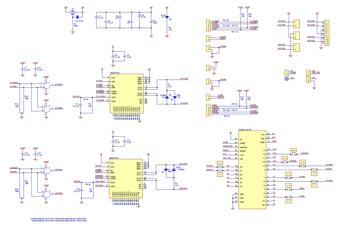 |
Schematic diagram of the Dual TB9051FTG Motor Driver Shield for Arduino. |
|---|
PDF of schematic: Dual TB9051FTG Motor Driver Shield schematic (299k pdf).
Related products


Home | Forum | Blog | Support | Ordering Information | Lists | Distributors | BIG Order Form | About | Contact
© 2001–2026 Pololu Corporation
