Support » Pololu Simple Motor Controller G2 User’s Guide » 4. Connecting your motor controller »
4.2. Serial/I²C interface pins
The 0.1"-spaced pins along the left side of the board make it possible to connect the Simple Motor Controller G2 to a microcontroller (e.g. an A-Star, Orangutan Robot Controller, or Arduino) or other logic-level serial I²C device, allowing for the creation of autonomous, self-contained systems. This section explains each of these pins in detail. See Section 6 for information on the Simple Motor Controller’s serial/I²C settings and protocols. See Section 4.3 for serial wiring examples and see Section 4.4 for I²C connection examples.
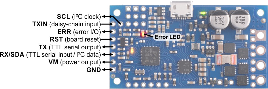 |
High-Power Simple Motor Controller G2 18v15 or 24v12 serial and I²C connections. |
|---|
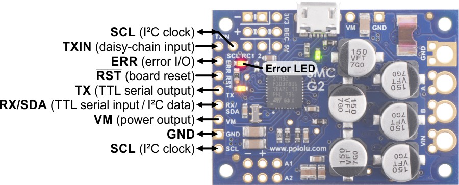 |
High-Power Simple Motor Controller G2 18v25 or 24v19 serial and I²C connections. |
|---|
The GND pin is a ground connection point. It is electrically connected to the large GND holes on the right side of the board, and the pins labeled with a minus sign in the RC section. Your serial or I²C device must share a common ground with the Simple Motor Controller G2.
The VM pin provides access to the board’s reverse-protected motor power. The voltage on this pin is not regulated; it will generally be equal to VIN or a little bit lower. This pin is not designed to provide a large amount of current.
The RX/SDA pin acts as RX, the TTL serial receive pin, by default. This pin can be connected to the TTL serial output (transmit line) of another device. When I²C is enabled, this pin acts as SDA: an input and open-drain output for sending data. In serial mode, this pin has an internal pull-up resistor enabled, but in I²C mode it does not have any pull-up or pull-down resistors. The RX/SDA pin is 5V-tolerant and protected by a 220Ω series resistor.
The TX pin acts as the TTL serial transmit pin. This pin can be connected to the TTL serial input (receive line) of another device. This connection is only required if you want to read information from the motor controller via serial. The TX pin is always an output, and it uses 0 V and 3.3 V voltage levels. The TX pin is protected by a 220Ω series resistor.
The SCL pin acts as the I²C clock signal. The Simple Motor Controller G2 uses a feature of I²C called clock stretching, which means that it will briefly drive this line low while handling I²C transfers. When I²C is disabled, which is the default, this pin acts as a secondary TX pin that ignores the TXIN input. This pin does not have any pull-up or pull-down resistors. The SCL pin is 5V-tolerant and protected by a 220Ω series resistor. The 18v25 and 24v19 versions have two duplicate SCL pins.
The RST pin is an active-low reset pin. This pin is internally pulled high; driving it low resets the motor controller. You must wait for at least 1 ms after a reset before transmitting to the controller. This pin can be left disconnected in most applications. This pin is not 5V-tolerant.
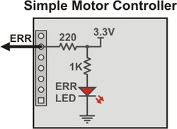
The ERR pin outputs high (3.3 V) when there is an error that is stopping the motor, turning on the red error LED in the process. Otherwise, it is weakly pulled low.
Because the ERR pin never drives low, it is safe to connect the ERR pins of multiple Simple Motor Controllers to the same microcontroller input. If any one of those controllers experiences an error, the microcontroller error input goes high and the error LEDs of all connected Simple Motor Controllers light up.
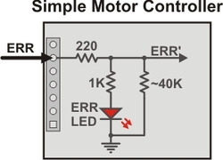
By default, the ERR pin is also configured to serve as an input that stops the motor when externally driven above 2.3 V. This means that the error lines of multiple controllers can be connected together and all controllers will shut down their motors when any one controller experiences an error. This technique of connecting error lines can be used even when RC signals or analog voltages are used to control the motors.
The following diagrams show the internal circuitry of the ERR pin in the error case (driving high to report an error) and in the error-free case (pulled low and configured as an input):
|
|
The TXIN pin is a special input that allows multiple G2 Simple Motor Controllers to be chained together without requiring an external AND gate. Connecting the transmit output of another serial device to this pin will cause that device’s transmissions to be output from the Simple Motor Controller G2’s TX pin. Inside each Simple Motor Controller, an AND gate is used to combine the input from the TXIN pin with the controller’s own serial transmissions. As long as only one device is transmitting at a time, the transmissions of all chained devices can be read by a single microcontroller receive line. This pin is 5V tolerant. The following diagram shows the internal circuitry of the TX and TXIN pins:
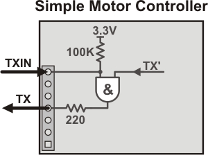 |
Schematic diagram of the Simple Motor Controller TXIN and TX pins. |
|---|
Related products


Home | Forum | Blog | Support | Ordering Information | Lists | Distributors | BIG Order Form | About | Contact
© 2001–2026 Pololu Corporation
