Support » Pololu Simple Motor Controller G2 User’s Guide » 4. Connecting your motor controller »
4.1. Connecting power and a motor
Warning: Take proper safety precautions when using high-power electronics. Make sure you know what you are doing when using high voltages or currents! During normal operation, this product can get hot enough to burn you. Take care when handling this product or other components connected to it.
The first step in using your Simple Motor Controller is connecting power and a motor. With those connections in place, you can immediately start testing with the Simple Motor Control Center G2 software. The following section explains the power system in detail.
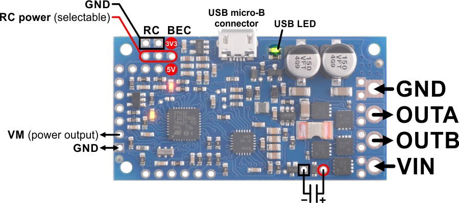 |
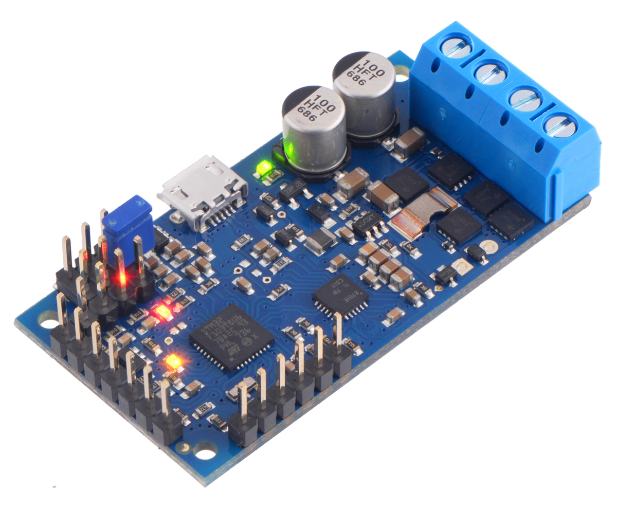
High-Power Simple Motor Controller G2 18v15 or 24v12 power and motor connections. |
|---|
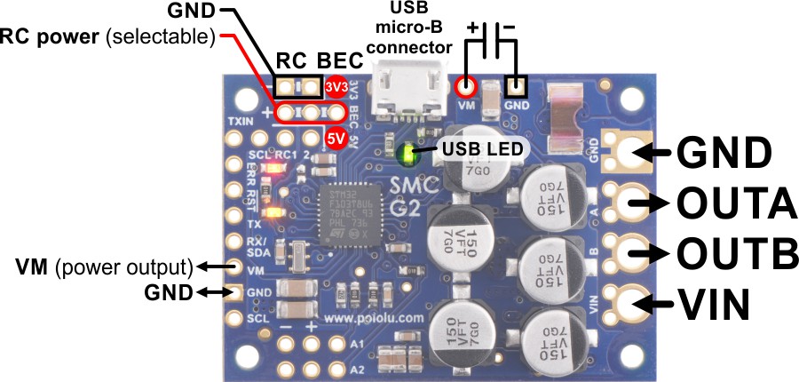 |
High-Power Simple Motor Controller G2 18v25 or 24v19 power and motor connections. |
|---|
Power considerations
The G2 Simple Motor Controllers can be powered either from USB using a USB A to Micro-B cable or from a power supply, such as a battery pack, connected to the large VIN and GND pads. When the VIN supply is not present, the controller can use USB power to perform all of its functions except for driving the motor. The controller automatically selects VIN as the power source when it is present, even when USB is connected. It is OK to have both USB and VIN power simultaneously connected.
All Simple Motor Controller G2 versions can operate from VIN supplies as low as 6.5 V. The maximum power ratings for the G2 Simple Motor Controllers are shown below:
 18v15 |
 24v12 |
 18v25 |
 24v19 |
|
|---|---|---|---|---|
| Minimum operating voltage: |
6.5 V | 6.5 V | 6.5 V | 6.5 V |
| Recommended max operating voltage: |
24 V(1) | 34 V(2) | 24 V(1) | 34 V(2) |
| Max nominal battery voltage: |
18 V | 28 V | 18 V | 28 V |
| Max continuous current (no additional cooling): |
15 A | 12 A | 25 A | 19 A |
1 30 V absolute max.
2 40 V absolute max.
It is very important that you select a power source that does not exceed the absolute maximum voltage rating for your controller. Ripple voltage on the supply line can raise the maximum voltage to more than the average or intended voltage, so we recommend you to select a voltage that leaves at least a 6 V margin for noise. It is also important to note that batteries can be much higher than their nominal voltage when fully charged, so we do not recommend using the 18v15 or 18v25 versions with 24 V batteries unless appropriate measures are taken to limit the peak voltage.
For 24 V applications, we recommend the 24v12 or 24v19 versions. We strongly recommend against using the 18v7, 18v15, or 18v25 with 24 V batteries, which can significantly exceed 24 V when fully charged and are dangerously close to the maximum voltage limits of these lower-voltage controllers. Using a 24 V battery with an 18vX Simple Motor Controller makes the device much more susceptible to damage from power supply noise or LC voltage spikes.
Finally, make sure you select a power source that is capable of delivering the current your motor will require (e.g. alkaline cells are typically poor choices for high-current applications).
The Simple Motor Controller G2 features a configurable low-voltage shutoff that can help you avoid damaging batteries that are sensitive to over-discharging, such as Li-Po packs. See Section 5.3 for more information.
Motor considerations
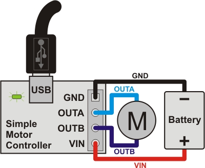 |
The two terminals of your brushed, DC motor connect to the OUTA and OUTB pins (which are just labeled “A” and “B” on some boards). When selecting a motor for your controller (or a controller version for your motor), it is important to consider how the motor will be used in your system. If the motor is likely to be stalled for prolonged periods of time or under heavy load, or if the motor will be rapidly changing direction without acceleration limiting enabled, you should be taking into account the stall current of the motor at the voltage it will be running and selecting a controller that can deliver a continuous current that exceeds the stall current.
It is not unusual for the stall current of a motor to be an order of magnitude (10×) higher than its free-run current. When a motor is supplied with full power from rest, it briefly draws the full stall current, and it draws nearly twice the stall current if abruptly switched from full speed in one direction to full speed in the other direction.
Occasionally, electrical noise from a motor can interfere with the rest of the system. This can depend on a number of factors, including the power supply, system wiring, and the quality of the motor. If you notice parts of your system behaving strangely when the motor is active (e.g. corrupted serial data, bad RC pulses, noisy analog voltage readings, or the motor controller randomly resetting), consider taking the following steps to decrease the impact of motor-induced electrical noise on the rest of your system:
- Solder a 0.1 µF ceramic capacitor across the terminals of your motor, or solder one capacitor from each terminal to the motor case. For the greatest noise suppression, you can use three capacitors (one across the terminals and one from each terminal to the case).
- Make your motor leads as thick and as short as possible, and twist them around each other. It is also beneficial to do this with your power supply leads.
- Route your motor and power leads away from your logic connections if possible.
- Place decoupling capacitors (also known as “bypass capacitors”) across power and ground near any electronics you want to isolate from noise.
- Add a capacitor across the GND and VM pins that are marked with a capacitor symbol in the diagrams at the top of this section.
Power and motor connectors
|
|
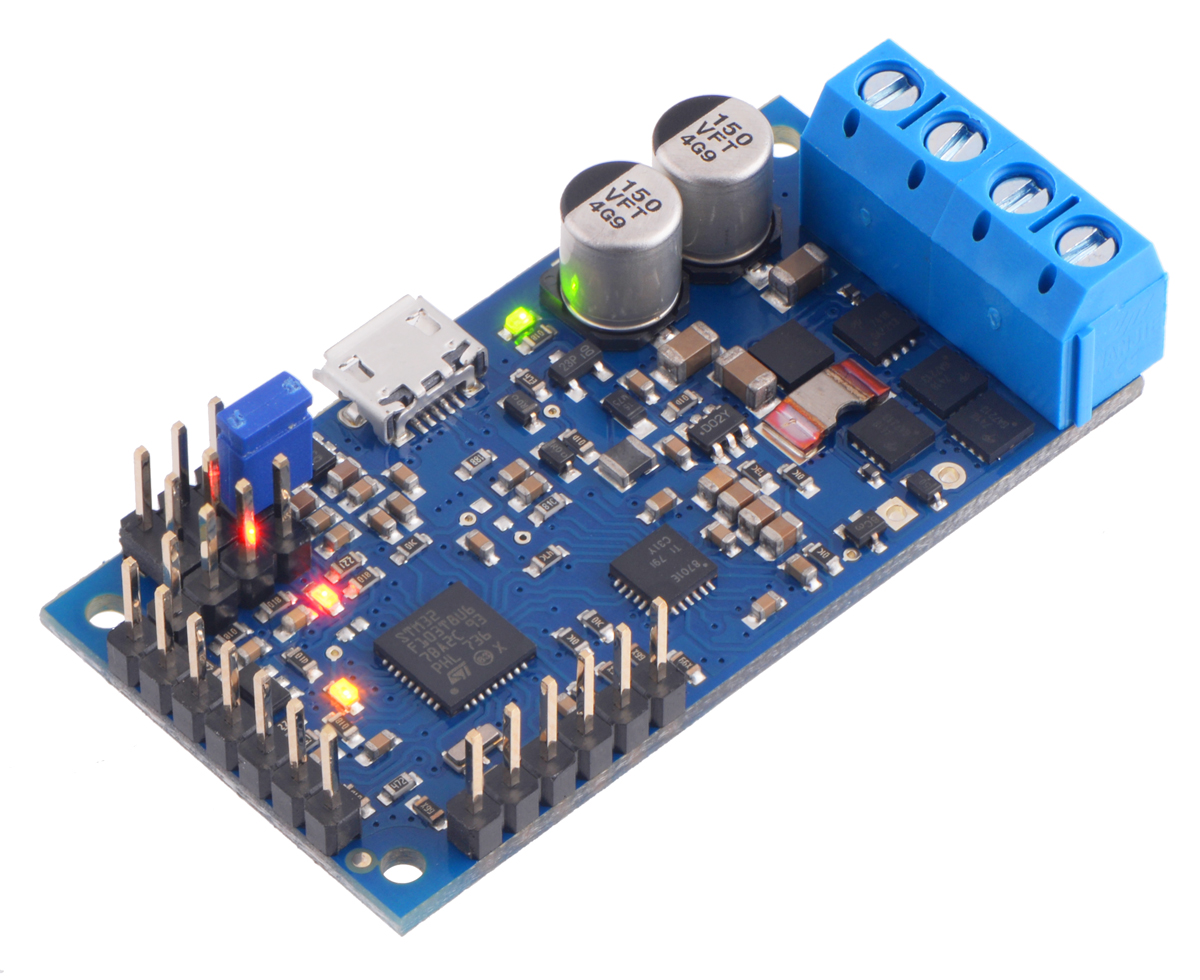
The fully-assembled 18v15, and 24v12 controller versions ship with terminal blocks soldered into the large VIN, OUTA, OUTB, and GND pads, as shown in the pictures above. These terminal blocks make it easy to connect and disconnect wires, but they are only rated for 15 A.
|
|
||||
|
|
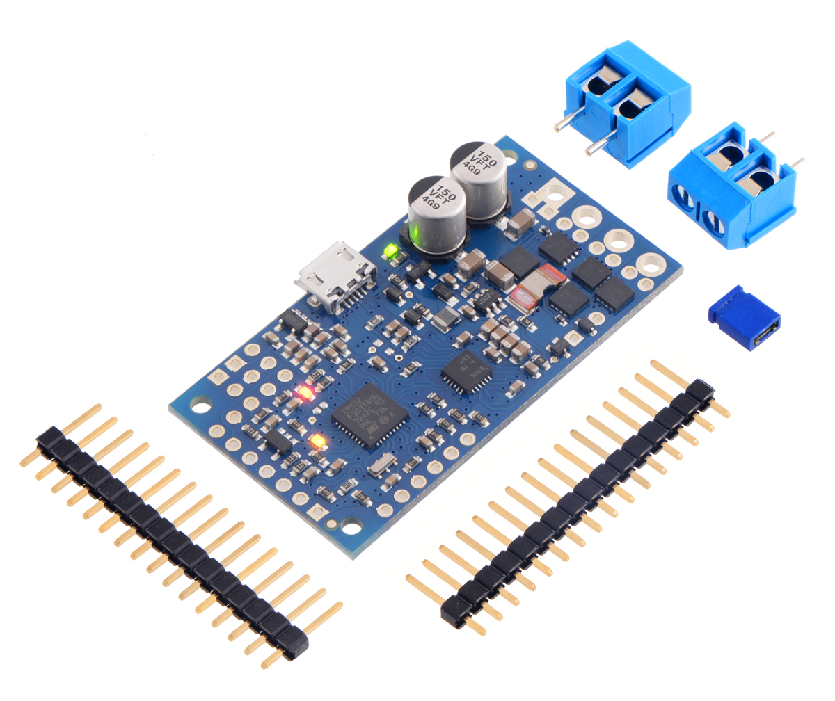
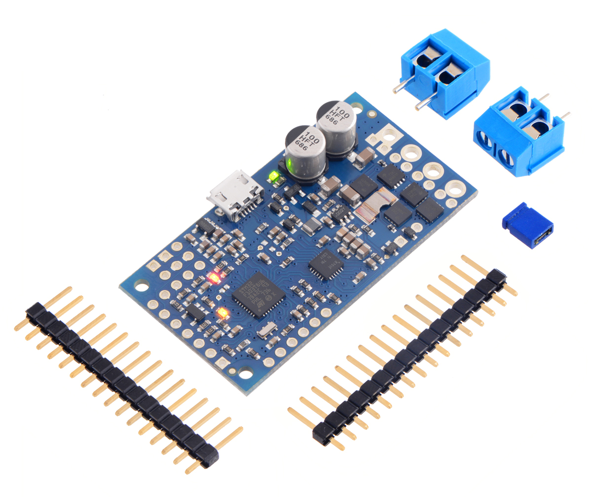
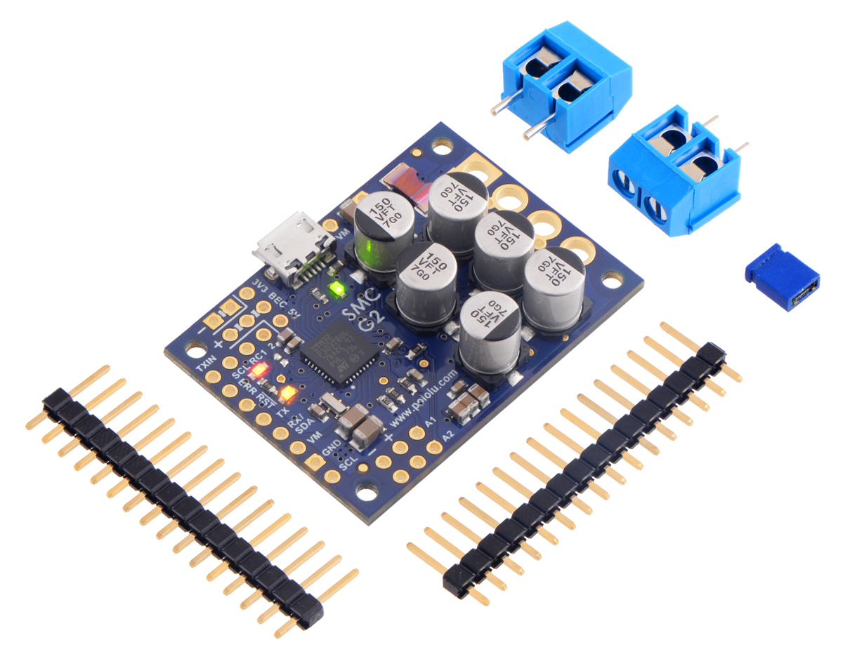
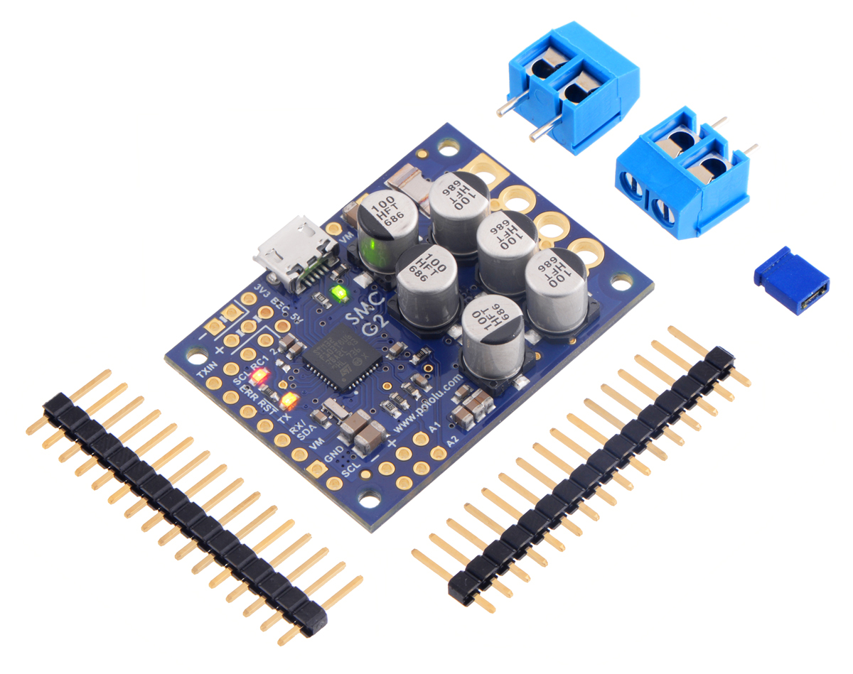
All other versions ship with terminal blocks and male header pins included but not installed, which provides flexibility in making connections. These versions offer two options for connecting to the high-power signals (VIN, OUTA, OUTB, GND): large holes with 5 mm center-to-center spacing, which are compatible with the included terminal blocks, and pairs of 0.1"-spaced holes, which are compatible with the included header pins and can be used with perfboards, breadboards, and 0.1" connectors. For high-power applications that exceed the 15 A rating of the terminal blocks, we recommend soldering thick wires directly to a connector-free version of the board and using higher-current connectors.
Logic power
The Simple Motor Controllers use 3.3 V logic, but all of the controllers’ digital inputs are 5V-tolerant, so it can interface directly with 5V systems. The only pins on the board that cannot tolerate 5V are the two analog input channels, A1 and A2. The simple motor controllers incorporate both a 5V regulator and a 3.3V regulator, but the 5V regulator is only used when power is supplied to VIN. Otherwise, the USB 5V bus voltage replaces the output of the 5V regulator. The 5V and 3.3V power buses are available via the RC BEC jumper pads (see the upper-right corners of the power connection diagrams above), and a shorting block can be used to connect the RC power row to the desired voltage rail, thereby powering a connected RC receiver with 3.3 or 5 V. These pins can also be used to supply approximately 150 mA to other components in your system.
Trying out the controller with USB
Once you have a connected a power supply and a motor, you can use the Simple Motor Control Center G2 to make the motor move and test how various settings affect the behavior of the motor (see Section 5 for more information on configuring the Simple Motor Controller G2). The Simple Motor Controller G2 defaults to “Serial/USB” input mode, which lets you control the motor speed with the slider bar under the status tab. If you have already changed the input mode of the device to something else, you can restore it by going to the “Input settings” tab, selecting Serial/USB as the input mode, and clicking the “Apply settings” button in the lower right corner.
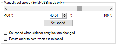 |
The “Manually set speed” box in the Status tab of the Simple Motor Control Center G2. |
|---|
Before you can move the motor, you will probably need to click the green Resume button in the lower left corner to clear the safe-start violation. If the Resume button is grayed out, there are errors that are preventing the motor from moving. See Section 3.3 for information on how to identify and fix errors.
Safe Start is an optional feature, enabled by default, that makes it less likely that the motor will start moving unexpectedly.
Related products


Home | Forum | Blog | Support | Ordering Information | Lists | Distributors | BIG Order Form | About | Contact
© 2001–2026 Pololu Corporation
