Support » Pololu Simple Motor Controller G2 User’s Guide »
6. Using the serial and I²C interfaces
- 6.1. Serial and I²C settings
- 6.2. Binary commands
- 6.3. ASCII commands
- 6.4. Controller variables
- 6.5. Cyclic redundancy check (CRC) error detection
- 6.6. Serial daisy chaining
This section documents the following three interfaces of the Simple Motor Controller G2:
- The USB virtual serial port (COM port), which is part of the USB interface.
- The TTL serial port, consisting of the controller’s RX and TX pins.
- The I²C interface, consisting of the controller’s SDA and SCL pins.
Each of these three interfaces support the same binary command protocol, as described in Section 6.2.
The TTL serial and USB virtual serial port also support an ASCII protocol as described in Section 6.3.
You can use these interfaces to set the speed of the motor when the controller’s “Input mode” setting is Serial/USB. In any input mode, you can use these interfaces to request information about the motor controller’s state and monitor the RC and analog channel inputs.
The Simple Motor Controller G2 treats each interface independently, so it is OK to use the USB serial port while simultaneously using TTL serial or I²C.
The Simple Motor Controller G2 can also be controlled using its native USB interface (see Section 7), which uses its own, separate protocol.
USB virtual serial port
The Simple Motor Controller G2 installs as two devices, one of which is a virtual serial command port. On Windows, you can identify the controller’s COM port number by looking in your computer’s Device Manager and expanding the “Ports (COM & LPT)” category.
On Linux, the serial port name will be something like /dev/ttyACM0.
On macOS, the serial port name will be something like /dev/cu.usbmodemfa121.
You can use a terminal program or computer software to send commands to this virtual serial port over USB. Most common programming languages have libraries for sending serial data (e.g. Visual C# has a SerialPort class), which makes it easy to write a custom computer program to control the Simple Motor Controller G2. See Section 8 for code examples. The baud rate settings do not matter when communicating through the virtual COM port.
TTL serial port
The controller’s serial receive line, RX, can receive bytes from a TTL serial source, such as a microcontroller, which allows for integration into embedded systems. The RX line expects a logic-level (0 to 2–5 V, or “TTL”), non-inverted serial signal.
The voltage on the RX pin should not go below 0 V and should not exceed 5 V.
The Simple Motor Controller G2 provides logic-level (0 to 3.3 V) serial output on its serial transmit line, TX. The bytes sent by the motor controller on TX are typically responses to commands that request information, but they can also be data received by the TXIN pin and passed on. If you aren’t interested in receiving TTL serial bytes from the motor controller, you can leave the TX line disconnected. See Section 4.3 for more information on connecting a serial device to the Simple Motor Controller.
The serial interface is asynchronous, meaning that the sender and receiver are separately configured ahead of time to agree on the length of a bit (this is known as the “baud rate” and it is usually specified in bits per second, or bps), and each side independently times the serial bits. The Simple Motor Controller G2 has the ability to automatically detect the baud rate, which means that it can be used even when the baud rate of the serial source is unknown as long as the serial source initiates communication by sending the proper baud rate indication byte: 0xAA (written as 170 in decimal notation). The Simple Motor Controller G2 works with baud rates from 1200 to 500,000 bits per second. Asynchronous TTL serial is available as hardware modules called “UARTs” on many microcontrollers, but it can also be “bit-banged” by a standard digital output line under software control.
The data format is 8 data bits, no parity bit, and one stop bit, which is often expressed as 8-N-1. The diagram below depicts a typical asynchronous, non-inverted TTL serial byte:
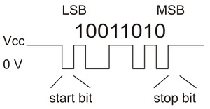 |
Diagram of a non-inverted TTL serial byte. |
|---|
A non-inverted TTL serial line has a default (non-active) state of high. A transmitted byte begins with a single low “start bit”, followed by the bits of the byte, least-significant bit (LSB) first. Logical ones are transmitted as high (3.3 V) and logical zeros are transmitted as low (0 V), which is why this format is referred to as “non-inverted” serial. The byte is terminated by a “stop bit”, which is the line going high for at least one bit time. The Simple Motor Controller G2 supports fixed baud rates of 1099 bps to 2 Mbps and can automatically detect baud rates up to 500 kbps in auto-detect baud rate mode.
You must wait for at least 1 ms after the Simple Motor Controller powers up or is reset before you start sending data. Anything sent during this first millisecond is likely to be ignored or incorrectly received.
Whenever connecting devices, remember to wire the grounds together, and ensure that each device is properly powered. Unpowered devices with a TTL serial port can turn on or partially on, drawing power from the serial line, which means that extra care must be taken when turning power off and on to reset the devices.
Note: TTL serial is not the same as RS-232 serial. You must use an inverter and level shifter such as a MAX232 or a Pololu 23201a Serial Adapter if you want to interface an RS-232 device with the Simple Motor Controller. Connecting an RS-232 device directly to the Simple Motor Controller can permanently damage it.
For more information about the serial pins, see Section 4.2.
I²C
The Simple Motor Controller G2’s I²C interface consists of its SDA pin and its SCL pin. The SDA pin is the same physical pin as the RX pin, and the SCL pin is linked to the TX pin, so you cannot use serial and I²C at the same time. I²C is disabled by default, so you must enable it by checking the “Enable I²C” checkbox in the “Input settings” tab of the Simple Motor Control Center G2. For more information about the I²C pins, see Section 4.2. For more information about connecting an I²C device, see Section 4.4.
To send commands to the I²C interface, you would first send the I²C START condition, followed by the 7-bit device number of the controller you want to address, then a zero bit to indicate that you are going to write to the controller. Next, transmit all the bytes of one or more binary command packets. Then end the write transfer using a STOP condition. All of the bytes transferred also have acknowledgment bits, as described in the I²C specification.
If you want to read data from the controller using I²C, the command for reading the data should be the last command you send in the write transfer. After ending the write transfer, start a read transfer: send an I²C START condition, followed by the 7-bit device number, and then a one bit to indicate that you are reading. Then read as many bytes of the response as you want to read. Finally, end the read transfer using a STOP condition. It is OK to only read a portion of the response, or to read nothing.
The Simple Motor Controller G2 uses I²C clock stretching, meaning that it will drive the SCL pin low sometimes while it is busy handling a transfer.
Related products


Home | Forum | Blog | Support | Ordering Information | Lists | Distributors | BIG Order Form | About | Contact
© 2001–2026 Pololu Corporation
