Support » Pololu Simple Motor Controller G2 User’s Guide » 6.3. ASCII commands »
6.3.1. ASCII command reference
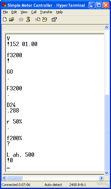 |
Sending ASCII commands to the Simple Motor Controller from HyperTerminal (with echoing of typed characters enabled). |
|---|
Exit safe-start (Serial/USB input mode only)
Command format: “GO<CR>”
Description: This command clears the Serial/USB safe-start violation and allows the motor to run. When safe-start protection is enabled, this command must be issued when the controller is first powered up, after any reset, and after any error stops the motor.
Motor forward (Serial/USB input mode only)
- “F1600<CR>”
- “F50%<CR>”
- “F640H<CR>”
Command format: “F<speed><CR>”
Description:
This command sets the motor target speed in the forward direction. The argument speed can be an integer from 0 (motor stopped) to 3200 (motor forward at full speed) or an integer percentage from 0% to 100%. You can represent the speed in hex by putting an “H” at the end of the number. If the argument speed is outside the allowed range, a Serial Format Error occurs..
Examples: The following commands all make the motor drive forward at half speed:
Motor reverse (Serial/USB input mode only)
Command format: “R<speed><CR>”
Description: This command sets the motor target speed in the reverse direction. It behaves the same as the Motor Forward command above, except the motor turns in the opposite direction.
Motor brake (Serial/USB input mode only)
- “B32<CR>”
- “B100%<CR>”
- “B20H<CR>”
Command format: “B<brake_amount><CR>”
Description:
This command causes the motor to immediately brake by the specified amount (configured deceleration limits are ignored). The argument brake_amount can be an integer from 0 (maximum coasting) to 32 (full braking) or an integer percentage from 0% to 100%. You can represent the brake amount in hex by putting an “H” at the end of the number. If the argument brake_amount is outside the allowed range, a Serial Format Error occurs.
Error. Examples: The following commands all make the motor brake as hard as possible:
Get variable
- “D24<CR>”
- “D18H<CR>”
Command Format: “D<variable_id><CR>”
Description:
This command lets you read a variable from the Simple Motor Controller G2. See Section 6.4 for a list of the available variables. The value of the requested variable is transmitted as an ASCII-encoded decimal number. If variable_id argument is invalid, a serial format error occurs.
Example: The following commands both request the board temperature (variable ID 24, or 0x18):
We might receive “.286<CR><LF>” as a response. The leading ‘.’ is a status character that indicates the last command was understood and no errors are currently stopping the motors. The rest of the characters before the carriage return (<CR>) and new line (<LF>) characters are an ASCII representation of a decimal (base 10) number. This particular variable has units of 0.1 °C, which would mean that the board temperature is 28.6 °C.
Set motor limit
- “L10,500<CR>”
- “LAH,1F4H<CR>”
- “L10,1F4H<CR>”
Command format: “L<limit_id>,<limit_value><CR>”
Description: This command lets you change the temporary motor limit variables documented in Section 6.4. Limit IDs from 0 to 3 affect both forward and reverse limits equally (they are “symmetric”). Limit IDs from 4 to 7 affect only forward limits and limit IDs from 8 to 11 affect only reverse limits. The following table provides the limit IDs for all of the temporary motor limit variables along with the allowed limit values:
| ID | Name | Allowed values | Units |
|---|---|---|---|
| 0 or 4 | Max speed forward | 0–3200 | 0=0%, 3200=100% |
| 1 or 5 | Max acceleration forward | 0–3200 (0=no limit) | Δspeed per update period |
| 2 or 6 | Max deceleration forward | 0–3200 (0=no limit) | Δspeed per update period |
| 3 or 7 | Brake duration forward | 0–16384 | 4 ms |
| 0 or 8 | Max speed reverse | 0–3200 | 0=0%, 3200=100% |
| 1 or 9 | Max acceleration reverse | 0–3200 (0=no limit) | Δspeed per update period |
| 2 or 10 | Max deceleration reverse | 0–3200 (0=no limit) | Δspeed per update period |
| 3 or 11 | Brake duration reverse | 0–16384 | 4 ms |
Note: The brake duration units used by this command are 4 ms, which differs from 1 ms units used by the brake duration variables returned by the “Get variable” command.
Note that the hard motor limit settings place restrictions on the limit values you can set with this command (see Section 5.2 for more information on the hard motor limits). The hard limits configured through the Simple Motor Control Center G2 are considered minimal safety requirements, and the temporary limits cannot be changed in a way that makes the controller “less safe” than this. This means that the maximum speed, acceleration, and deceleration temporary limits cannot be increased beyond their hard-limit counterparts and the Brake Duration limits cannot be decreased below their hard-limit counterparts. If you try to set a temporary limit in a way prohibited by the corresponding hard limit, the temporary limit value is set to the hard limit and the response code byte indicates that the value could not be set as requested.
If the arguments to this command are valid, the controller responds to this command with an ASCII digit:
| Response Code | Description |
|---|---|
| ‘0’ | No problems setting the limit. |
| ‘1’ | Unable to set forward limit to the specified value because of hard motor limit settings. |
| ‘2’ | Unable to set reverse limit to the specified value because of hard motor limit settings. |
| ‘3’ | Unable to set forward and reverse limits to the specified value because of hard motor limit settings. |
Limit IDs above 11 and limit values outside of their allowed value ranges result in a serial format error.
The limit values set with this command persist only until the controller is next reset or the “Apply settings” button is next clicked in the Simple Motor Control Center G2, at which point the temporary limit settings are all reinitialized to the hard limit settings.
Example: The following commands all set the reverse deceleration limit (limit ID 10, or 0x0A) to 500, or 0x1F4:
The controller might send “.0<CR><LF>” as a response. The leading ‘.’ is a status character that indicates the last command was understood and no errors are currently stopping the motors. The following character, ‘0’, means that the temporary limit was set as requested. If our max deceleration reverse hard motor limit was below 500, this character would have been ‘2’, which would tell us that the temporary limit was not set as requested (rather, it was set equal to whatever the hard limit is).
Get firmware version
Command format: “V<CR>”
Description: This command prints the Simple Motor Controller G2 product number (in decimal) and firmware version number (the two major firmware version digits followed by the two minor firmware version digits). For example, the response to this command might be “.163 01.00<CR><LF>”, which indicates a product ID of 163, a major firmware version of 1, and a minor firmware version of 0.
Stop motor
Command format: “X<CR>”
Description: This command sets the motor target speed to zero and makes the controller susceptible to a safe-start violation error if safe start is enabled. Put another way, this command will stop the motor (configured deceleration limits will be respected) and not allow the motor to start again until the Safe-Start conditions required by the Input Mode are satisfied.
Related products


Home | Forum | Blog | Support | Ordering Information | Lists | Distributors | BIG Order Form | About | Contact
© 2001–2026 Pololu Corporation
