Support » Pololu Simple Motor Controller G2 User’s Guide » 5. Configuring your motor controller »
5.2. Motor settings
The “Motor settings” tab of the Simple Motor Control Center G2 allows you to set up limits to protect your system and lets you specify the details of how your motor should be driven.
 |
Motor settings tab in the Pololu Simple Motor Control Center G2. |
|---|
Hard limits
The Hard limits box allows you to set up hard limits on the motion of your motor in order to protect your system and reduce mechanical stress.
They are called Hard Limits because they are stored in non-volatile memory and they are always obeyed. However, all of them except “Starting speed” can be temporarily modified using the appropriate USB or serial command. Only modifications that make the system safer are allowed. These temporary changes will only last until the next time the device resets, at which point the hard limits will be reloaded. See Section 6.2.1 for more details about setting temporary motor limits.
If you want to enter different limits for the reverse and forward directions, check the Asymmetric checkbox.
Max speed is a number between 0 and 3200 that specifies the maximum speed at which the motor controller will ever drive the motor. The default value is 3200, which corresponds to 100% and means there is no limit. A value of 0 means that the motor will not be allowed to drive in the specified direction. This setting also affects how the target speed is computed in RC and analog modes: after mixing is optionally performed, a scaled value of 3200 or −3200 maps to the Max speed. The Max speed should be zero or it should be greater than the Starting speed.
Starting speed is a number between 0 and 3200 that specifies the minimum speed at which the motor controller will ever drive the motor. The default value is 0, which means there is no minimum, so this setting has no effect. This setting also affects how the target speed is computed in RC or analog modes: after mixing is optionally performed, a scaled value of 1 means the target speed equals the forward starting speed and a scaled value of -1 means the target speed equals the inverse (negation) of reverse starting speed. The starting speed parameter allows you to save some energy by never driving the motor at speeds that are too low to actually make the motor turn. It can also make your joystick control be more accurate and responsive, because the motor can start moving as soon as the stick leaves the neutral area.
Max. acceleration is a number between 0 and 3200 that specifies how much the magnitude (absolute value) of the motor speed is allowed to increase every speed update period. The default value is 0, which means there is no limit. An acceleration limit can help reduce mechanical stress and help reduce current spikes when the motor is starting up. If an acceleration value of 1 is too fast for your application, you can increase the speed update period to make it slower.
Max. deceleration is a number between 0 and 3200 that specifies how much the magnitude (absolute value) of the motor speed is allowed to decrease every speed update period. The default value is 0, which means there is no limit. A deceleration limit can help reduce mechanical stress and help reduce current spikes when the motor is decelerating. Note that deceleration limits apply even when there is an error stopping the motor; depending on your setup, it might not be a good idea to use deceleration in conjunction with a limit switch because the motor will not stop as fast as possible when the limit switch is triggered. If an deceleration value of 1 is too fast for your application, you can increase the speed update period to make it slower.
Brake duration is the time, in milliseconds, that the motor controller will spend braking the motor (current speed = 0) before allowing the current speed to change signs. The forward brake duration is the braking time required before switching from forward to reverse (from positive to negative speeds). The reverse brake duration is the braking time required before switching from reverse to forward (from negative to positive speeds).
The Speed update period is the time, in milliseconds, between consecutive updates to the current speed. The default is 1 ms, which is the lowest allowed value. By increasing the speed update period, you can decrease the effective rate of acceleration and deceleration because the updates will be applied less often. The slowest possible acceleration/deceleration can be achieved by setting the Speed update period to 100 ms and the acceleration/deceleration limit to 1; with this configuration it will take 320 seconds to accelerate from speed 0 to speed 3200 (100 %) or decelerate from speed 3200 to speed 0.
Current limit
The Current limit setting sets the hardware current limit for the Simple Motor Controller G2’s motor driver; when the motor current exceeds this value, the driver will actively limit it using current chopping. Hardware current limiting is performed entirely by the motor driver, which means it can react quickly to current spikes (within a few microseconds).
The Simple Motor Controller G2 obtains a raw current sense measurement from the motor driver in the form of an analog voltage, which typically has an offset of about 50 mV when VIN is present, though the offset can vary widely from unit to unit. The controller converts this value into a current in units of milliamps with the following formulas (where the raw current sense measurement is Vraw and the reported current is I):
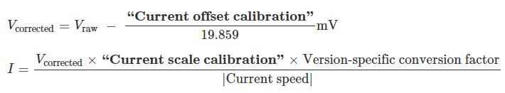 |
The default value of the Current offset calibration is 993, which corresponds to 50 mV. Increasing it makes the reported current lower, while decreasing it makes the reported current higher.
If the controller reports extremely high, inaccurate currents while the motor is driving at a low duty cycle, it might be due to the analog current sense signal from the motor driver having an offset higher than the typical 50 mV offset. You can make the current readings more accurate at low duty cycles by setting the “Current offset calibration” setting properly.
The easiest way to set the “Current offset calibration” setting is to connect power to VIN, make sure the motor is stopped, and then click the “Measure” button to measure the offset and automatically change the setting.
The default value of the Current scale calibration setting is 8057. Increasing it makes the reported current higher, while decreasing it makes the reported current lower.
Current limit setting: converting from milliamps to internal units
Internally, the current limit setting has a value between 0 and 3200 and uses internal units. The Simple Motor Control Center G2 software lets you enter the desired current limit in Amps, and converts to the internal units for you. However, if you want to set the current limit using the “Set current limit” serial/I²C command, you will need to do that conversion yourself by following these steps:
- Take the desired current limit in units of milliamps and multiply it by 3200.
- Multiply this number by the following number, which depends on the Simple Motor Controller G2 model: 2 for the 18v15, 3 for the 24v12, 1 for the 18v25, or 2 for the 24v19.
- Divide by the current scale calibration setting (8057 by default).
- Add the current offset calibration setting (993 by default).
- Multiply by 3200 and then divide by 65536 to get the final result.
Current limit measurement: converting from a raw measurement to milliamps
The Simple Motor Controller G2 reports the motor current in milliamps, but it also reports a raw current measurement reading. This reading is the voltage on the current sense line: 0 represents 0 V, while 65536 represents 3300 mV. If you want to do the calculation to convert the raw reading to milliamps yourself, follow these steps:
- Take the raw current measurement and subtract the current offset calibration setting (993 by default) from it. If this yields a negative number, the current is 0 mA and you can skip the steps after this one.
- Multiply the result by the current scale calibration setting (8057 by default).
- Divide by the following number, which depends on the Simple Motor Controller G2 model: 2 for the 18v15, 3 for the 24v12, 1 for the 18v25, or 2 for the 24v19.
- Divide by the absolute value of the current motor speed as a number from 1 to 3200. If the motor speed is 0, treat the current as 0 mA instead.
Other motor settings
The Invert motor direction option lets you switch the meanings of forward and reverse. By default, forward means the average voltage on OUTA is greater than the average voltage on OUTB (and reverse means the opposite). With the Invert motor direction option enabled, forward means the average voltage on OUTA is less than the average voltage on OUTB.
The PWM frequency setting specifies the frequency of the rapidly-switching (PWM) signal used to control the speed of the motor. Several PWM frequency options are available between 1.13 and 22.50 kHz. The default PWM frequency is 22.50 kHz. This is an ultrasonic frequency; it is too high for humans to hear, so you won’t hear the high-pitched whine from the motor that other motor controllers can cause. Using a lower PWM frequency will reduce switching losses and slightly increase the power output to the motor because the duty cycle (the percentage of the time that the H-bridge is powering the motor) can be closer to 100%.
The When motor is off setting specifies the controller’s behavior when the current speed is zero (because of an error or any other reason). The default option is Brake, which means that the controller will drive its motor outputs low, the motor will brake, and it will be relatively hard to turn the motor by hand. If you would prefer that your motor stop more gradually or be easier to turn while it is stopped, you can use the Coast option, which causes the motor outputs to be disabled instead. Another way to have gradual stops is to set a deceleration limit, which will cause the current speed to slowly drop to zero.
Related products


Home | Forum | Blog | Support | Ordering Information | Lists | Distributors | BIG Order Form | About | Contact
© 2001–2026 Pololu Corporation
