Support » Pololu Simple Motor Controller G2 User’s Guide » 6. Using the serial and I²C interfaces »
6.1. Serial and I²C settings
The behavior of the Simple Motor Controller G2’s USB virtual serial port, TTL serial port, and I²C interfaces is determined by a number of settings, almost all of which can be found under the “Input settings” tab of the Simple Motor Control Center G2:
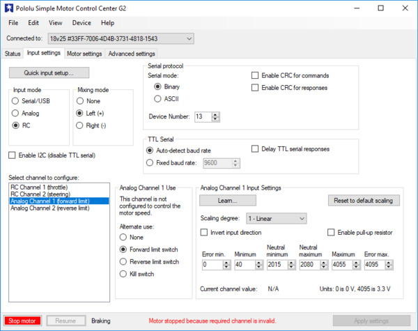 |
Input settings tab in the Pololu Simple Motor Control Center G2. |
|---|
The Enable I2C (disable TTL serial) option enables the I²C interface on the SDA and SCL pins, and disables the serial interface on the RX and TX pins. You should only enable this option if you intend to use I²C.
The Serial mode setting determines which protocol the Simple Motor Controller G2 will accept on its virtual serial port and TTL serial port. It does not affect I²C.
- Binary: In this mode, the controller expects command packets comprised of a series of bytes that conform to the Compact, Pololu, or Mini SSC protocol formats (see Section 6.2 for more information on these protocols). The binary mode commands are more compact than their ASCII mode counterparts, so they can be transmitted faster. This mode also lets you send commands addressed to a particular device number, so this mode should be used when multiple devices are daisy-chained together on the same serial line.
- ASCII: In this mode, the controller expects command packets comprised of ASCII characters, which makes the commands potentially more friendly to beginners since they look like character strings rather than seemingly random sets of bytes. Also, the ASCII protocol makes it easy to send commands to the Simple Motor Controller G2 from a terminal program. See Section 6.3 for more information on the ASCII protocol.
When the Enable CRC for commands option is enabled, the Simple Motor Controller G2 requires a cyclic redundancy check (CRC) byte at the end of every binary mode command packet, which helps ensure that the controller won’t misinterpret noisy commands or act up when presented with a stream of random serial bytes (see Section 6.5 for more information on CRCs). If the CRC byte is not appended or is incorrect, the controller reports a serial CRC error. CRC is not available for ASCII mode commands.
When the Enable CRC for responses option is enabled, the Simple Motor Controller G2 will append a CRC byte onto the end of every binary mode response it generates, which lets you be more confident that the response was not corrupted by noise. CRC is not available for ASCII mode responses.
The Device number is a number between 0 and 127 that can be used to address this device in Pololu Protocol and Mini SSC protocol commands. This setting is useful when using the Simple Motor Controller G2 with other devices in a daisy-chained configuration (see Section 6.6). The “Device number” is also used as the 7-bit I²C address of the device, which must be transmitted as the first 7 bits of every I²C transfer. If you are connecting multiple controllers to the same serial bus or to the same I²C bus, each controller should have a different device number.
There are two options for determining the baud rate on the TTL serial port (the RX and TX pins). These settings do not apply to the USB virtual serial port or the I²C interface.
- Auto-detect baud rate: In this mode, the Simple Motor Controller G2 automatically detects the baud rate from the first 0xAA (170) baud rate indication byte it receives on the RX line. Every time the controller is powered up or reset, and every time you apply new settings to the controller, you will need to send a baud rate indication byte before the controller will accept TTL serial commands. Once you send the baud rate indication byte, you can check the Status tab of the Simple Motor Control Center G2 to see what baud rate the controller detected. The controller can automatically detect baud rates from 1200 bps to 500 kbps. This mode is only available when the serial mode is “Binary”; the fixed baud rate option is automatically selected when the serial mode is “ASCII”.
- Fixed baud rate: In this mode, the Simple Motor Controller G2 will only respond to TTL serial signals transmitted at the configured fixed baud rate (in units of bits per second, or bps). The fixed baud rate can be set from 1099 bps to 2 Mbps, but the Simple Motor Controller will not be able to keep up with a constant stream of commands at baud rates over 500 kbps (if you send commands to the controller faster than it can process them, the receive buffer will eventually fill up, data will be lost, and a serial RX overrun error will be generated).
Enabling the Delay TTL serial responses feature causes the Simple Motor Controller G2 to wait for approximately 4 ms before transmitting a TTL serial response. This is useful when interfacing with devices like the Basic Stamp that use half-duplex UARTs and need time to switch from transmit mode to receive mode. When this feature is disabled, transmission of a response packet begins as soon as possible after the last byte of a command packet is received (if that command packet generates a response).
The Command timeout setting lets you configure the Simple Motor Controller to shut down the motor if too much time elapses between received commands, which could happen if your serial control source gets disconnected or loses power. It is located under the “Advanced settings” tab of the Simple Motor Control Center G2. See Section 5.3 for more information on this parameter.
Related products


Home | Forum | Blog | Support | Ordering Information | Lists | Distributors | BIG Order Form | About | Contact
© 2001–2026 Pololu Corporation
