Support » Pololu m3pi User’s Guide » 2. Assembly »
2.a. Adding Components to the Top of the Expansion PCB
This section will guide you through adding components to the top side of the m3pi expansion board, which requires through-hole pins to be soldered on the underside of the PCB. Please note that the components you actually need depend on how you plan on using the board, so you do not need to install components you know you will not be using. For example, if you never plan on using your mbed as a USB host, you do not need to solder in the USB A connector. Section 4 contains detailed descriptions of these components and can help you determine which components you will need for your particular application. However, there is no harm in installing them all, and doing so gives you maximum flexibility (maybe you’ll change your mind down the road and decide you want to try out using the mbed as a USB host after all).
 |
Assembly location diagram for the m3pi’s top-side components and headers. |
|---|
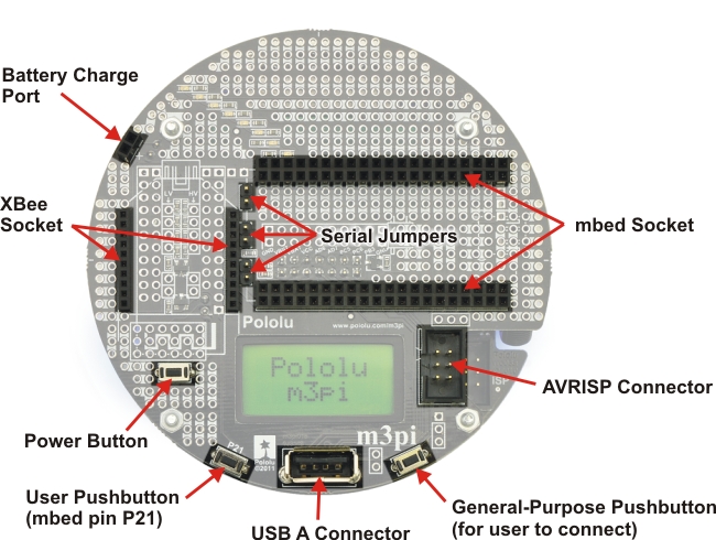 |
Assembly location picture for the m3pi’s top-side components and headers. |
|---|
 |
Pololu m3pi expansion kit after assembly. |
|---|
mbed Socket
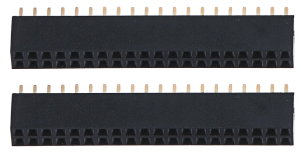 |
If you want to use an mbed development board as the main controller of your m3pi robot, you should solder the two 2×20 0.1″ female headers to create a socket for the mbed as shown in the two diagrams at the top of this section. See Section 4.a for more information on the mbed socket.
XBee Socket
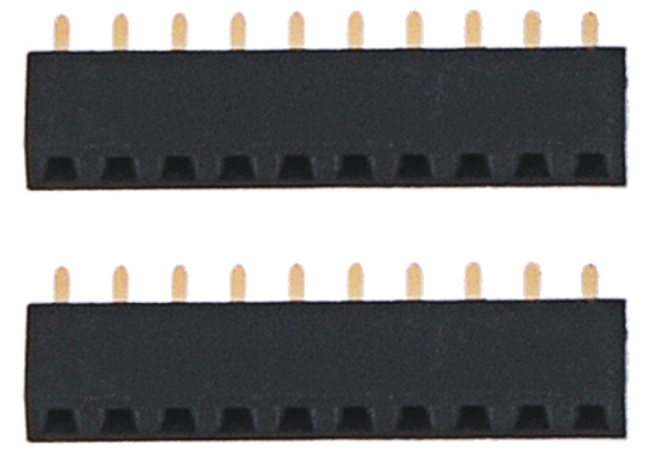 |
If you want to use an XBee module to add wireless functionality to your m3pi robot, you should solder the two 1×10 2mm female headers to create a socket for the XBee as shown in the two diagrams at the top of this section. Note that the XBee headers are the only included female headers with a 2mm (0.079″) pitch, so they are noticeably smaller than all the rest. See Section 4.a for more information on the XBee socket.
Battery Charge Port
|
|
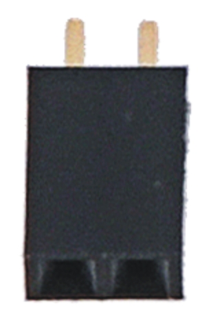
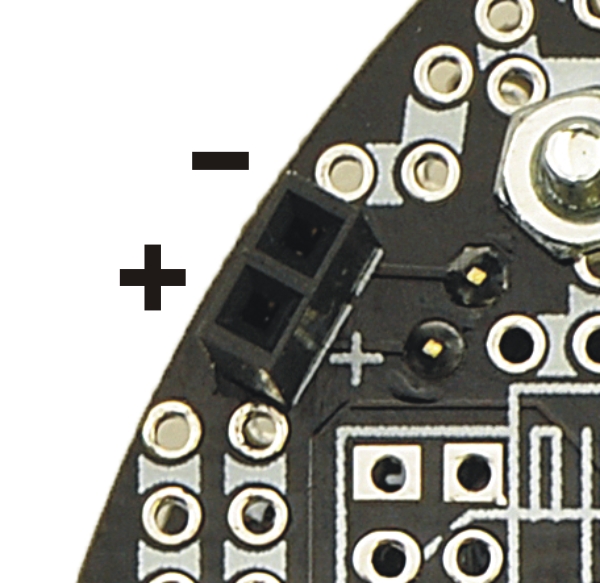
The expansion PCB makes it difficult to reach the battery charge port on the 3pi robot base, so it has connectors that bring the port up to the expansion PCB for easier access. One of the included 1×2 0.1″ female headers can be used as a battery charge port when soldered to the m3pi expansion PCB as shown in the two diagrams at the top of this section. See Section 4.f for more information about the battery charge port.
Pushbuttons
 |
The m3pi expansion kit includes three pushbuttons that can be used to add a power button and two general-purpose user buttons to the m3pi expansion PCB. The locations for these buttons are shown in the two diagrams at the top of this section. See Section 4.c for more information about the pushbuttons.
Serial Jumpers
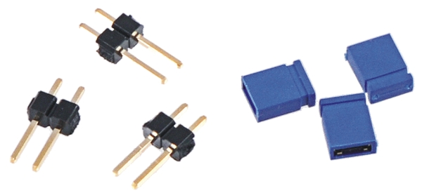 |
If you want to be able to connect the serial lines of an XBee or Wixel wireless module directly to the serial lines of the 3pi base (e.g. to use the Wixel as the m3pi’s main controller or to make the m3pi a serial slave to a remote device), you should solder the three included 1×2 0.1″ male headers to create the serial jumpers shown in the two diagrams at the top of this section. Be sure to solder the short ends of the headers to the PCB so that the full extent of the long ends protrude up. The included shorting blocks can then be placed over the protruding header pins to establish the alternate serial connections. See Section 4.a for more information about the serial jumpers.
USB A Connector
|
|
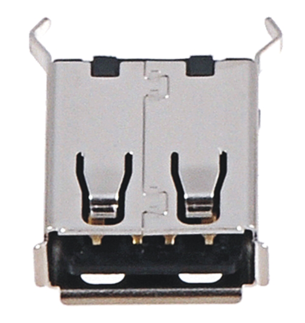
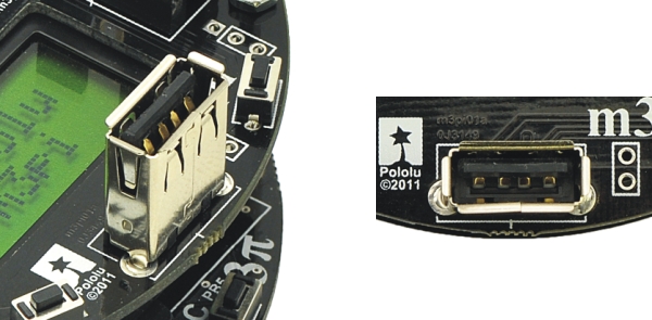
The m3pi expansion kit includes a USB A header that lets you connect USB devices to your mbed if it is programmed to act as a USB host. Please note that when installing the USB A connector, the two large protrusions from the case must be soldered to the PCB along with the four logic pins. These large protrusions provide structural support for the connector when they are soldered into the large holes in the PCB. The location for the USB A connector is shown in the two diagrams at the top of this section. Please see Section 4.h for more information about the USB A connector.
AVRISP Connector
 |
If you want to use your mbed as an AVR programmer (e.g. to reprogram the microcontroller on the 3pi base), you should solder the shrouded and keyed six-pin (2×3) 0.1″ male header to the m3pi PCB as shown in the two diagrams at the top of this section. Please note that this header can be installed two different ways, but only one orientation is correct: pin 1 on the header, denoted by a triangle in the plastic, must connect to pin 1 on the PCB, denoted by a caret on the silkscreen and an octagonal pad (and the gap in the shroud faces the LCD cutout). This header will not work if it is installed incorrectly, so please verify the orientation before you start soldering. Please see Section 4.g for more information about the AVRISP connector.
Wixel Socket
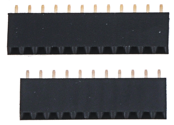 |
If you want to add wireless functionality to your m3pi robot with a Wixel module (or if you want to use the Wixel, which is programmable, as the main controller for your m3pi rather than an mbed), you should solder the included 1×11 and 1×12 0.1″ female headers to create a Wixel socket as shown in the following picture:
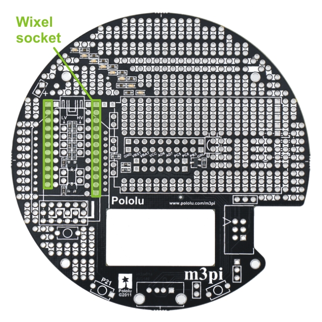 |
m3pi locations for the 1×11 and 1×12 0.1″ female Wixel socket headers. |
|---|
Note: The Wixel socket headers are taller than the XBee socket headers, so you will no longer be able to use the XBee socket once you add the Wixel socket. For this reason, the fully-assembled version of the m3pi does not ship with the Wixel socket installed. You should only add this socket if you are sure you do not want to use an XBee module for your wireless communication.
Please see Section 4.a for more information about the Wixel socket.


Home | Forum | Blog | Support | Ordering Information | Lists | Distributors | BIG Order Form | About | Contact
© 2001–2026 Pololu Corporation
