Support » Pololu m3pi User’s Guide » 4. The Expansion Board in Detail »
4.a. mbed and Wireless Module Sockets
The m3pi expansion board makes it easy to add an mbed development board as the m3pi’s main controller, and it supports the addition of one of several different wireless modules (see Section 1.c for more information). The following diagram shows where these modules connect on the m3pi expansion PCB:
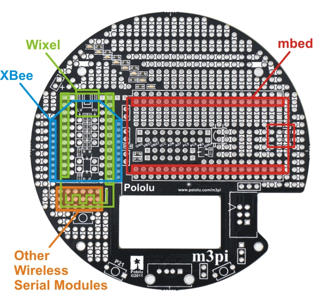 |
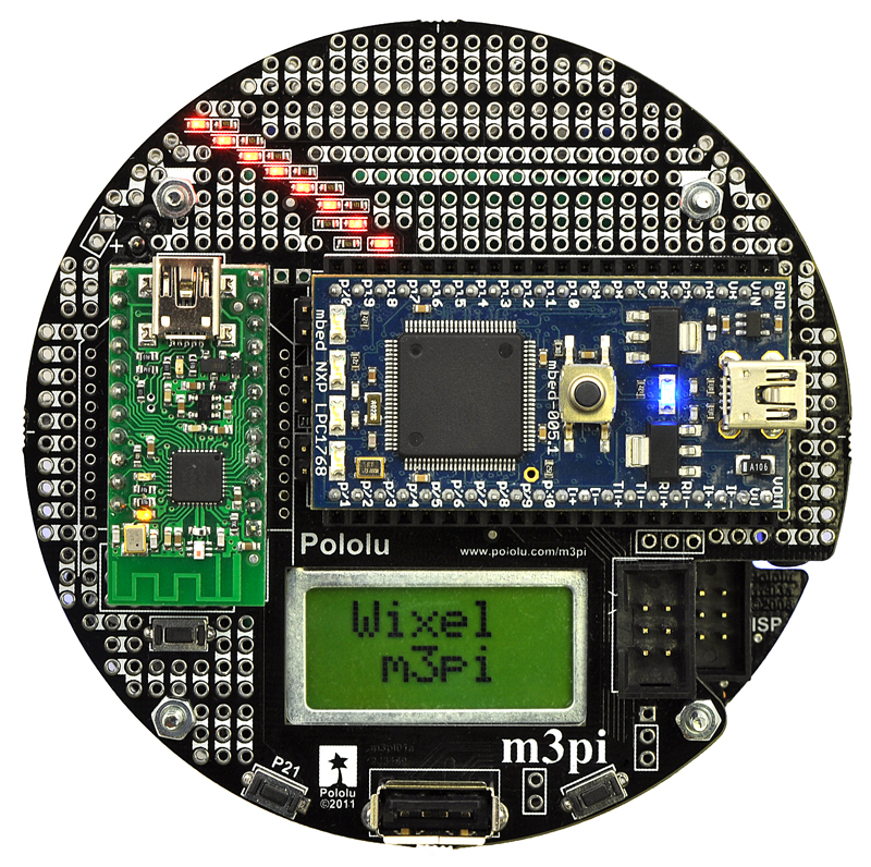
The m3pi expansion board ships as shown in the above picture, with the headers required to make sockets for these modules included but not soldered in. The m3pi robot ships with the mbed and XBee socket headers already soldered in. Headers for the Wixel socket are included but not soldered because they would interfere with the XBee socket. The orange highlighted area in the above diagram consists of six columns of linked pins that you can use with other wireless serial modules, such as Bluetooth. The pins in this general-purpose space are not connected to the serial lines of the mbed or 3pi base, so you would need to route the appropriate pins to the appropriate places yourself (the exact routing depends on the pin-out of your module). No headers are included for this general-purpose wireless serial module space.
|
|

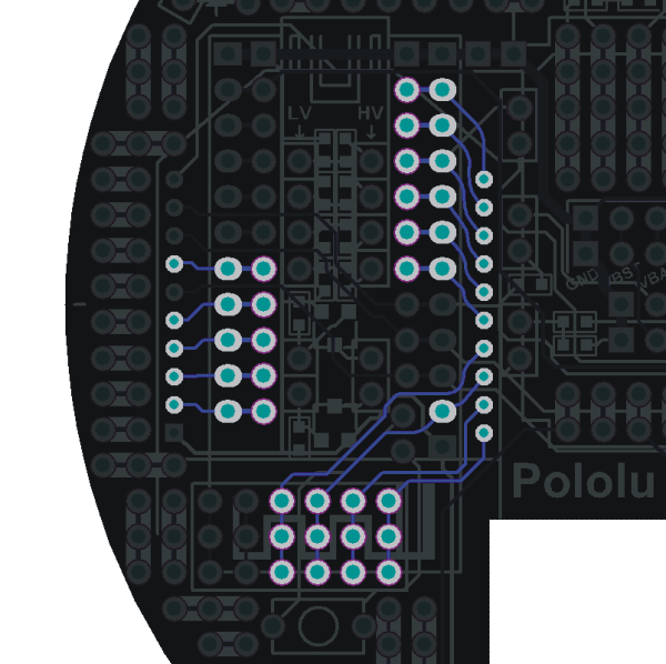
The m3pi expansion PCB connects mbed pins P9 and P10 directly to the serial RX (PD0) and TX (PD1) pins of the 3pi base, respectively. It also connects mbed pin P8 to the 3pi’s reset pin (PC6) through a level-shifting MOSFET. The level shifter also acts as an inverter, so driving P8 high resets the 3pi. The 3pi serial and reset pins can also be connected directly to a socketed Wixel or XBee via a set of three jumpers, which allows you to use the 3pi as a wireless serial slave without an mbed, or you can program the Wixel to serve as the robot’s main controller. The following diagram shows how the mbed and jumpers connect to the 3pi robot base:
 |
m3pi serial and reset connections to the 3pi robot base. |
|---|
Note: You should not use these jumpers if your m3pi robot has a socketed mbed.
The m3pi expansion PCB also connects mbed pins P27 and P28 to the serial TX and RX pins, respectively, of the Wixel and XBee sockets, and it connects mbed pin P26 to the Wixel and XBee socket reset lines (driving P26 low resets the wireless devices). This means that the mbed NXP LPC1768 can use one UART to send and receive wireless data while using a second UART to control the 3pi base. (The mbed NXP LPC11U24 only has one UART and cannot interface with a wireless module while controlling the 3pi.)
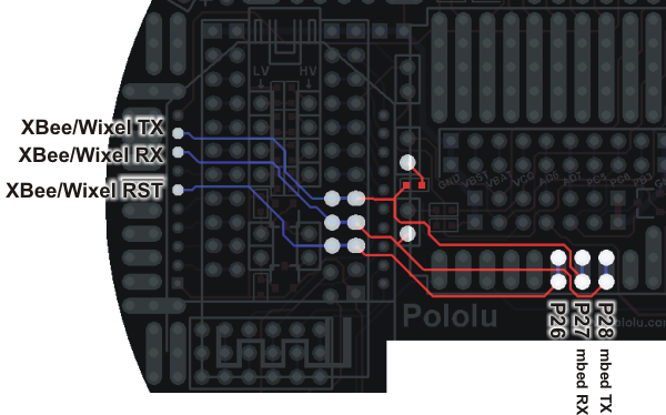 |
m3pi serial and reset connections between the XBee or Wixel and the mbed. |
|---|
The following schematic shows the m3pi’s serial connections:
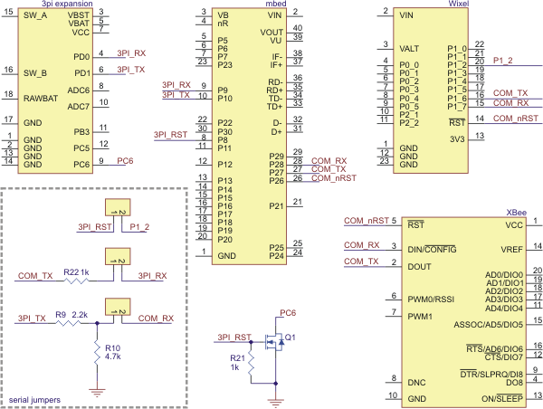 |
m3pi schematic diagram of the serial connections between the various components. |
|---|
The unused Wixel and XBee pins are connected together as shown in the diagram below. It is not possible to simultaneously use a Wixel and XBee, so these connections exist to provide more multiple convenient access points for each of the unused Wixel and XBee pins.
 |
General-purpose Wixel or XBee pins can be accessed at multiple points on the m3pi expansion PCB. |
|---|
Warning: The mbed, Wixel, and Xbee use 3.3 V logic and the 3pi uses 5 V logic. While the mbed pins are 5V-tolerant, the Wixel and XBee pins are not. All of the dedicated connections between components on the m3pi expansion board perform the required level shifting, but you must be careful if you make your own connections to free Wixel or XBee pins. The m3pi expansion board has several general-purpose level shifters that you can use to safely make your own connections between components (see Section 4.d for more information).


Home | Forum | Blog | Support | Ordering Information | Lists | Distributors | BIG Order Form | About | Contact
© 2001–2026 Pololu Corporation
