Support » Pololu m3pi User’s Guide » 2. Assembly »
2.b. Connecting the m3pi Expansion Board to the 3pi Robot
The m3pi expansion board connects to the 3pi robot base via three extended male headers:
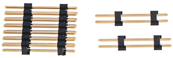 |
2×7 and two 1×2 0.1″ extended male headers used to connect the m3pi expansion PCB to the 3pi robot base. |
|---|
The short ends of these headers should be soldered to the m3pi expansion PCB in the locations shown in the pictures below; the long ends will plug into female headers on the 3pi robot base.
|
|

This requires the headers to be inserted through the appropriate through-holes from the underside of the PCB and then soldered on the top side of the PCB.
It is very important that the headers be soldered in straight or else they won’t line up properly with the headers on the 3pi robot base. We recommend you initially solder just one header pin and then check to see if the header is straight. If it is, proceed with soldering the rest of the pins. If it isn’t, melt the solder joint with your soldering iron and adjust the header (Note: the soldered header pin will get very hot when you do this, so do not touch this pin while making the adjustments!). It is very difficult to straighten a crooked header that is soldered in multiple places.
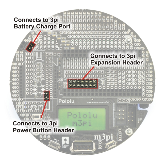
The m3pi expansion kit includes a 2×7 0.1″ female header and a 1×2 0.1″ female header that must be soldered to the 3pi robot base to act as receptacles for the extended male headers you just soldered to the m3pi expansion PCB:
 |
The 2×7 female header becomes the 3pi expansion header and the 1×2 female header becomes the 3pi power button header; the 3pi ships with the 1×2 female battery charge port header already soldered in. These two female headers should be soldered to the 3pi robot in the locations denoted by the red boxes in the picture below:
 |
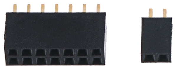
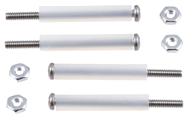
To connect the m3pi expansion PCB to the 3pi robot, female headers (red) and standoffs (yellow) are required. |
|---|
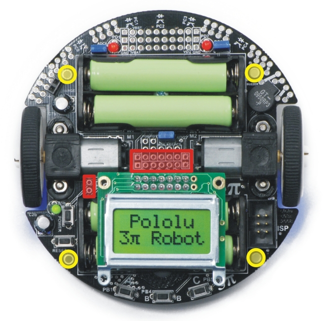
With these headers soldered in place, your 3pi will have the three female headers it needs to accept the three extended male headers you soldered to the m3pi expansion board:
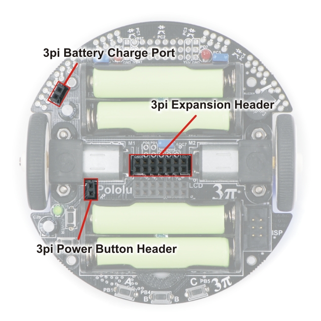 |
3pi robot female headers that connect to the male headers on the underside of the m3pi expansion PCB. |
|---|
Note: Be very careful to plug the expansion board into your 3pi correctly. The female headers do not strictly enforce proper positioning or orientation on their own. Additionally, remember to add batteries to your 3pi before you plug in the m3pi expansion board. We strongly recommend you use rechargeable batteries for your m3pi robot.
Four nylon standoffs, screws, and nuts are included for creating a more secure physical connection between the m3pi expansion board and the 3pi robot base. The screws work with the four large holes around the edge of the m3pi expansion board and the 3pi robot.
 |
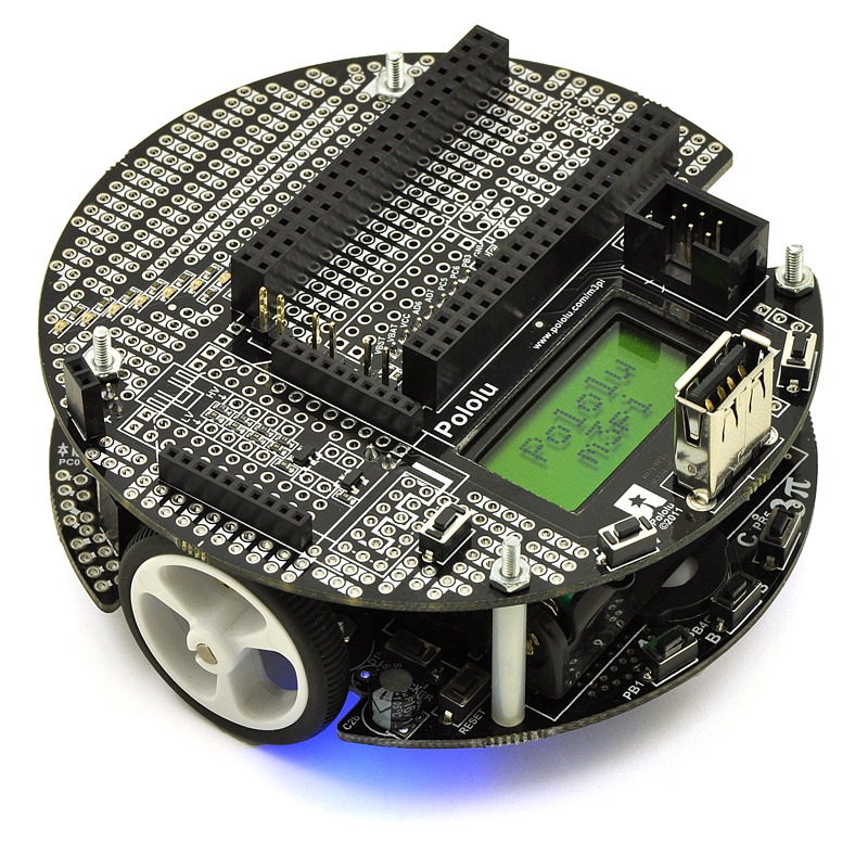
| When assembly is complete, you should have an m3pi robot that looks something like this (depending on which components you added in Section 2.a): | |
|


Home | Forum | Blog | Support | Ordering Information | Lists | Distributors | BIG Order Form | About | Contact
© 2001–2026 Pololu Corporation
