Support » Pololu Jrk USB Motor Controller User’s Guide » 3. Configuring the Motor Controller »
3.e. Motor Options
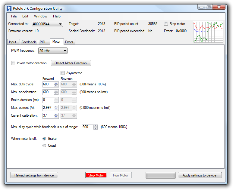 |
The Motor tab of the Jrk Configuration Utility |
|---|
The Motor tab of the jrk configuration utility controls the PWM signal applied to the motor, including all limits that are applied when converting duty cycle target to duty cycle.
The jrk’s PWM duty cycle has a range of -600 to 600, where -600 is full reverse and 600 is full forward. “Forward” and “reverse” should be consistent with the scaled feedback values, so that when the duty cycle is positive, the motor spins in a direction that increases the scaled feedback. By default, full forward (+600) means motor output A = VIN and B = 0 V, while full reverse (-600) means A = 0 V and B = VIN. When checked, the Invert motor direction option switches these definitions so that full forward (+600) means A = 0 V and B = VIN, while full reverse (-600) means A = VIN and B = 0 V.
Detect motor direction
To automatically detect whether the motor is inverted or not, click “Detect Motor Direction”. This will attempt to drive the motor with a gradually increasing duty cycle until it starts to move, as measured by the feedback. Make sure to configure feedback correctly before clicking this button, or the results will be meaningless. It is also recommended to set up low maximum duty cycles and currents, and set the Motor drive error, Feedback disconnect, and Max. current exceeded errors to be “Enabled and latched”, so that any potentially damaging conditions encountered during this test will cause the jrk to turn off the motor.
PWM frequency
The jrk is capable of both 20 kHz and 5 kHz PWM. The 20 kHz PWM frequency is ultrasonic and can thus eliminate audible PWM-induced motor humming, which makes this frequency desirable for typical applications.
However, a higher PWM frequency means greater power loss due to switching, which could make a 5 kHz PWM frequency a better choice for certain applications.
Additionally, the 5 kHz PWM frequency allows for finer control at duty cycles approaching 0% or 100% (±600). This is because the timing characteristics of the jrk motor drivers make it so that very short PWM pulses (either low or high) have no effect on the output voltage. This limitation is more pronounced on the jrk 21v3, in which pulses that are shorter than approximately 4 μs have no effect on the output voltage. Therefore, at 20 kHz, the jrk 21v3 with a duty cycle less than 8% will effectively have a duty cycle of 0% (braking), while a duty cycle greater than 92% will be the same as a duty cycle of 100% (the jrk 12v12 can typically go a bit closer to 0% and 100%). At 5 kHz, the effect is smaller by a factor of four: a duty cycle less than 2% will be the same as a duty cycle of 0% (braking) while a duty cycle greater than 98% will be the same as a duty cycle of 100%.
Limits
Various limits may be applied to the duty cycle, each of which can be configured separately for forward (positive duty cycle) and reverse (negative duty cycle) if the “Asymmetric” option is checked:
Max. duty cycle limits the duty cycle itself.
Max. acceleration limits the amount that the duty cycle can change by in a single PID period. For example, if there is an acceleration limit of 10 in both directions, and the current duty cycle is 300, then the duty cycle in the next PID period is limited to be within -10 to 310.
Max. current causes the jrk to measure the motor driver current and adjust the duty cycle as necessary to limit it the specified value. The current is reported as a number from 0 to 255 that is multiplied by the Current calibration to get a number in mA, so increasing the current calibration value will increase the measured value. For accurate current limiting, acceleration should be limited; otherwise the duty cycle will tend to oscillate when the maximum current is exceeded.
Brake duration is a feature that is most useful for large motors with high-inertia loads used with frequency feedback or speed control mode (no feedback). If this option is used, the jrk will automatically keep the motor at a duty cycle of 0 for the specified time before switching directions. The “forward” setting refers to switching from forward to reverse, and the “reverse” setting refers to switching from reverse to forward.
Max. duty cycle while feedback is out of range is an option to limit possible damage to systems by reducing the maximum duty cycle whenever the feedback value is beyond the absolute minimum and maximum values. This can be used, for example, to slowly bring a system back into its valid range of operation when it is dangerously near a limit. The Feedback disconnect error should be disabled when this option is used.
When motor is off
When the motor is off because of an error condition or an explicit Motor Off command, there are two options for the state of the motor driver: brake (A and B both connected to GND) and coast (A and B floating).
You can familiarize yourself with motor coasting and braking using nothing more than a motor. First, with your motor disconnected from anything, try rotating the output shaft and note how easily it turns. Then hold the two motor leads together and try rotating the output shaft again. You should notice significantly more turning resistance while the leads are shorted together.
The jrk 21v3 PWMs the motor outputs between driving and braking, and a duty cycle of zero is the same as braking.
The jrk 12v12 PWMs the motor outputs between driving and coasting when the duty cycle is non-zero.
As of firmware version 1.4, the behavior of the jrk 12v12 when the duty cycle is zero depends on the “When motor is off” configuration option. In previous versions, at a duty cycle of 0, the jrk 12v12 would brake the motor in one direction but let it coast in the other direction.


Home | Forum | Blog | Support | Ordering Information | Lists | Distributors | BIG Order Form | About | Contact
© 2001–2026 Pololu Corporation
