Support » Custom Laser Cutting Guide »
4. File set up instructions
We prepare your previews and laser-cut parts with CorelDRAW, which can handle a variety of vector and two-dimensional CAD drawings:
| File types we can use | File types we cannot use |
|---|---|
| ✓ CDR (CorelDRAW) | ✘ SLDDRW (SolidWorks) |
| ✓ AI (Adobe Illustrator) | ✘ SLDPRT (SolidWorks) |
| ✓ SVG (Inkscape) | ✘ SLDASM (SolidWorks) |
| ✓ EPS (Adobe Illustrator) | ✘ PSD (Adobe Photoshop) |
| ✓ DXF (must be 2D) | ✘ STEP |
| ✓ DWG (must be 2D) | ✘ STL |
| ✓ PDF (cut objects must be vector-based) | ✘ STP |
| Bitmap images (JPG, PNG, TIF, etc.) can be used for engraving and printing only (not for cutting) | ✘ Any other 3D format file |
Laser cutting file set up instructions
Following the instructions below to create your files will speed up the quote request and cutting process. If you are unable to set up your file, send us what you can (even if it is just a hand sketch and some notes), and we can try to provide a ballpark estimate, and let you know if we could create the file for you.
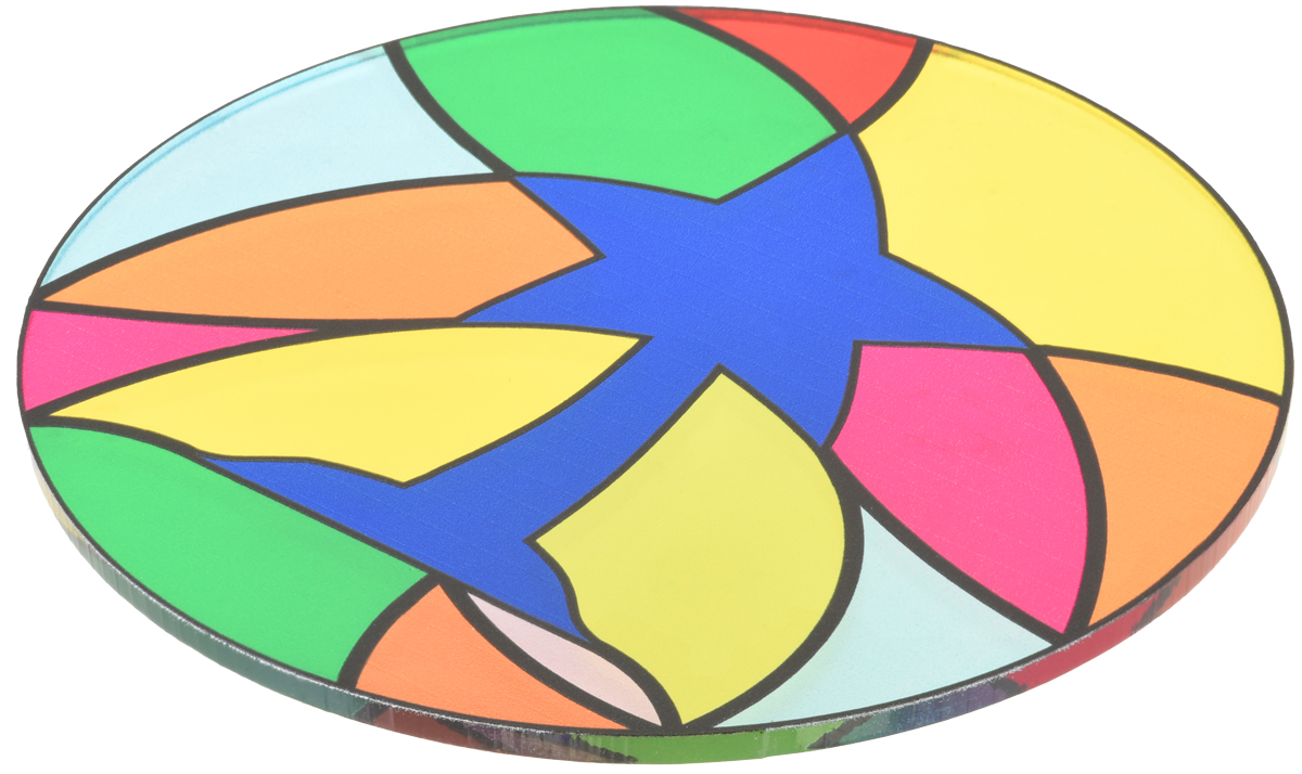
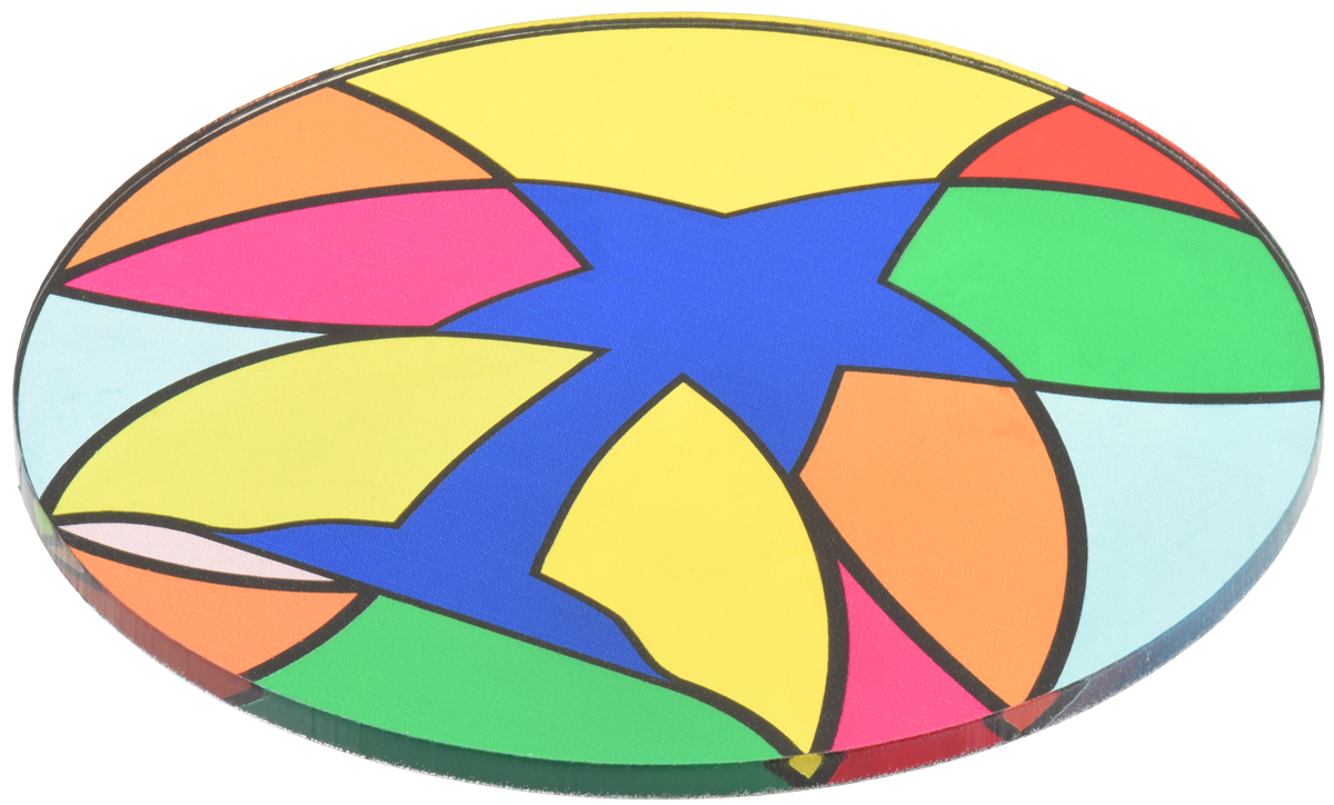
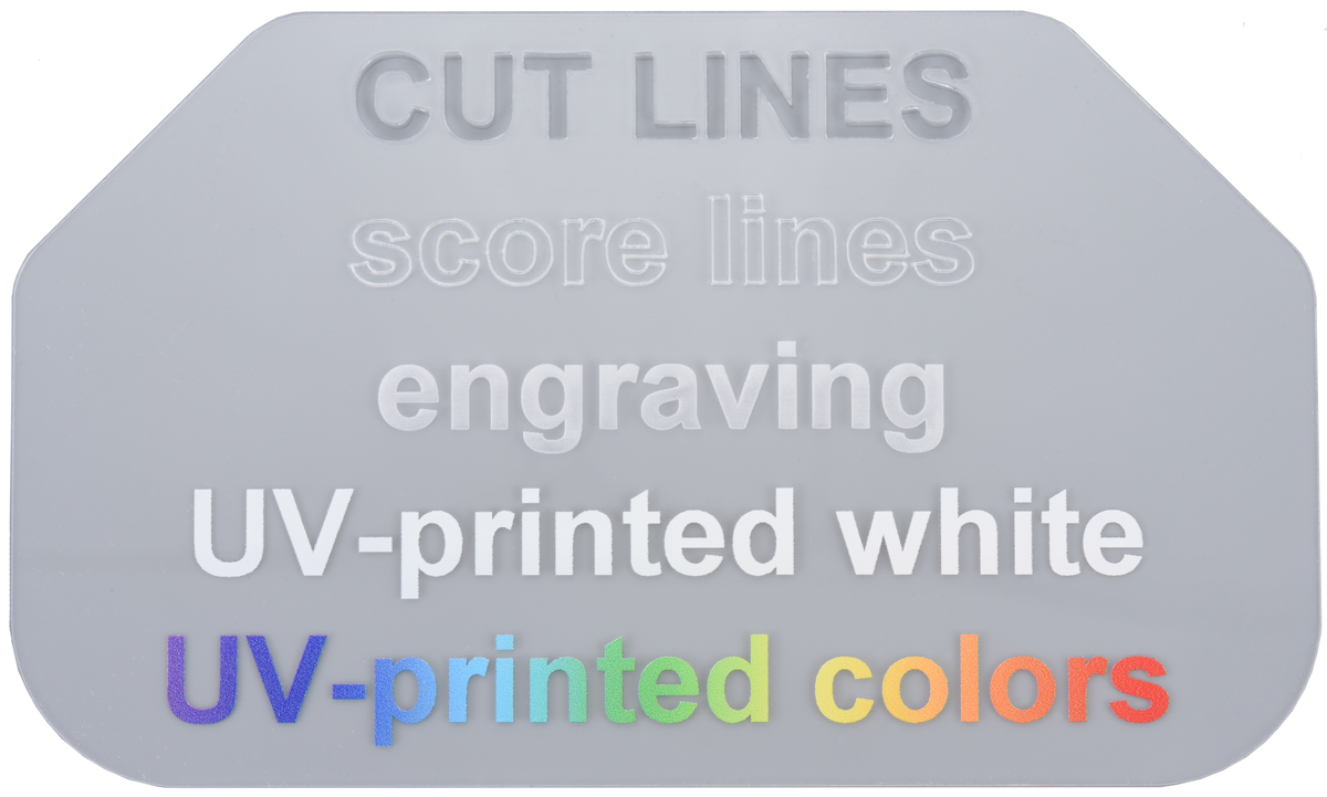
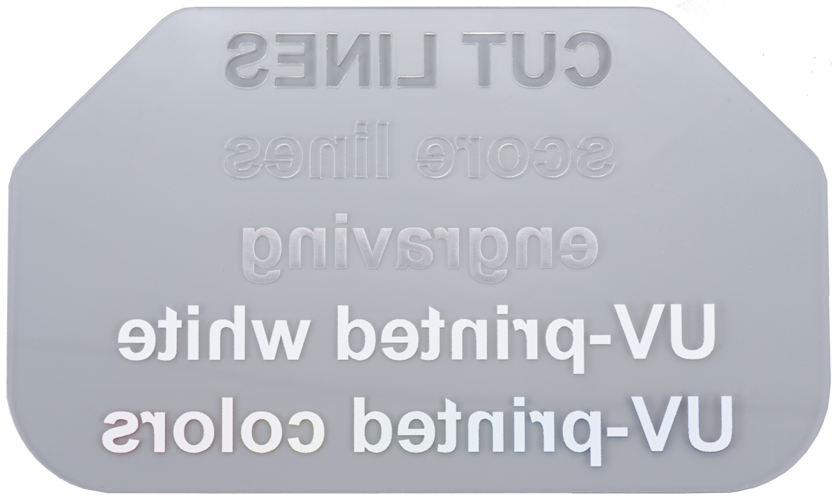
- Set up your file with different layers or colors for cut lines, score lines, engravings, UV-printed designs, and notes.
- Consider downloading one of our template files below to get started. They include preset layers for your cut lines as well as separate layers for all of our printing modes (color, white, primer, and clear).
- Add cutting designs and notes to your file, and use colors to make it easy to differentiate between design features. We prefer:
- Blue lines thinner than 0.003″ for cutting
- Red lines thinner than 0.003″ for scoring
- In some programs, you can define cutting/scoring lines by setting the stroke width to “0” or “hairline,” but do not set it to “none.”
- Black color-filled objects or lines thicker than 0.003″ for engravings
- Green for notes and reference objects that you do not want us to cut (e.g., part or material size references, special instructions, etc.)
Note: All engravings are surface-etched unless you specifically request deeper engraving.
- Add UV-printed artwork to each of the print layers using vector or bitmap objects.
- Your file should have a separate layer for each layer of ink you want to print.
- Arrange the printing layers in the order that you want us to print them in (bottom first, top last).
- See Section 6 for information about how to stack layers and UV-printing design advice.
Note: White, primer, and clear layers should be defined in non-white colors as our printer will ignore white objects and white areas.
Note: If your UV-print design uses bitmaps, we recommend configuring them with 1200 DPI resolution. See Section 6.1 for a more detailed explanation.
- Include a size reference with a label, such as a 1″ square, to your notes layer so it will be easy for us to verify the size of your layout and quote it accordingly.
- Combine parts that use the same material into a single file, and avoid sending multiple files whenever possible.
- Parts that should be cut from different materials should have separate files.
- Save the file in one of the file types we can use (see the table above) using a filename that is meaningful for you.
- Avoid common mistakes and errors by checking the following before you submit your file:
| ✓ | Verify all your designs and notes are correct, and that none of the designs you want cut from that material are missing. • If you are submitting multiple files for different materials, we suggest including the material as part of your file name, or having a prominent note. |
| ✓ | Check that your designs avoid features narrower than the material thickness. |
| ✓ | Make sure the artboard/canvas/page size actually fits all of your parts. |
| ✓ | Convert all text to non-text objects to ensure that your design is preserved. • Programs use different terms for this operation, such as “explode text,” “convert to curves/paths/objects/outline,” etc. |
| ✓ | Verify that your file includes a size reference. |
| ✓ | Confirm that your white, primer, and clear UV printing layers do not use white objects. |
| ✓ | Open the exact file you plan to submit, and make sure everything appears correctly. • This is especially important if you are exporting from your program into a different file type. For example, if you are exporting a SolidWorks file as a DXF, open and look at the DXF. |
Once you are done, you can submit all of your files in a quote request:
Downloadable template files
You can download one of our templates below, which already have the different layers set up.
 |
 |
 |
| CorelDRAW (340k cdr) | Adobe Illustrator (7MB ai) | Inkscape (457k svg) |
|---|
|
|
||||
|
|
Additional tips and tricks
Part design
- Round off corners for stronger parts that are less likely to crack upon impact.
- Even adding a 1/16″ radius to a 90° angle can make a big difference!
- Adjust for the kerf width (the thickness of the beam).
- The kerf width which is typically ~0.007″ – 0.010″, but varies based on many factors (see our Section 3 for more information).
- You can manually draw parts to be 0.007″ – 0.010″ wider (for exterior cuts) or smaller (for interior cuts).
- Some programs have automated line-offset or contour tools that will do this for you.
UV printing
- See Section 6 for information about our capabilities, limitations, and design advice for UV printing.
Efficient layouts
- Use layouts that work well with the material size (while reserving a 1/4″ margin) whenever possible.
- Standard plastic layout sizes:
- 11.5″ x 11.5″
- 11.5″ x 23.5″
- 23.5″ x 23.5″
- 23.5″ x 35.5″
- 23.5″ x 47.5″
- Standard steel and aluminum layout sizes:
- 23.5″ x 23.5″
- 23.5″ x 47.5″
- Standard plywood layout sizes:
- 11.5″ x 23.5″
- 23.5″ x 29.5″
- 29.5″ x 47.5″
- Standard plastic layout sizes:
Note: We can handle larger layouts – up to 47.5″ x 47.5″ – but we do not usually stock sheets this large and prefer working with smaller, more manageable, layouts whenever possible.
- Share lines to reduce cutting time for non-metal layouts by nesting parts right next to each other.
- Remember to delete one of the duplicate lines, otherwise this will not be effective. Even though you might not be able to see them in the file, the laser cutters will recognize and cut lines that are stacked on top of each other, which can worsen the cut quality.
- We can accept line-shared layouts for most plastics, woods, foams, and rubbers,
- We cannot use line-shared layouts for metals.
Programs for drawing laser-cut parts
- CorelDRAW is what we use and love. It is available as a one-time purchase or a yearly subscription, and as of the writing of this guide, they also offer a free 15-day trial.
- Adobe Illustrator is the most popular vector graphics editor available, making it easy to find online guides and tutorials. Monthly and yearly subscriptions are available, as well as a free trial.
- Inkscape is a free, open-source, vector graphics editor. While it works great for designing laser-cut parts, Inkscape’s default file format (SVG) often has scaling issues when opened with other programs, so please save your files as a PDF or EPS instead of an SVG when submitting your file for a quote.
- LibreCAD is a free, open-source, CAD software capable of creating two-dimensional CAD files for laser-cutting.
Related products


Home | Forum | Blog | Support | Ordering Information | Lists | Distributors | BIG Order Form | About | Contact
© 2001–2026 Pololu Corporation
