Support »
Building Line Following and Line Maze Courses
View document on multiple pages.
You can also view this document as a printable PDF.
- 1. About Line Following and Maze Solving
- 2. What You Will Need
- 3. Building the Line-Following Course
- 4. Building the Line Maze Course
1. About Line Following and Maze Solving
Line following is a great introduction to robot programming, and it makes a great contest: it’s easy to build a line-following course, the rules are simple to understand, and it’s not hard to program a robot to follow a line. Optimizing your program to make your robot zoom down the line at the highest speed possible, however, is a challenge that can introduce you to some advanced programming concepts.
When you’re ready for a more difficult task, build a line maze for your robot to solve. You can start by solving the maze with a simple “left hand on the wall” strategy and move up to more and more advanced techniques to make your robot faster.
In this tutorial, we’ll show you how to build a good-looking line following course and a line maze, step by step. The materials you’ll need (posterboard and electrical tape) are easy to find and should cost you under $10.
Suggested line following contest rules:
The contest is a single-elimination tournament in which two robots race against each other at a time, on two separate courses that are mirror images of each other. In each match of the contest, a robot races once on each course, and the robot with the best time (out of both races) is declared the winner of the match. A starting line must be marked on each course, in a way that will not interfere with the robots’ sensors. For example, the boundary between two segments of the course could be used. Two timers are used to time each robot for three laps.
A race proceeds as follows:
- The two robots are prepared for the race, including battery testing, calibration, etc.
- Each robot is placed approximately 1’ behind its starting line.
- The contestants wait for a starting signal, then start their robots simultaneously.
- When the robots cross the starting line, their timers are started. The starting time might be slightly different for the two robots.
- The time for three laps is measured, and the contestants stop their robots.
The robots must follow the line for the entire race. If there is ever a point in time when some part of the robot is not over the line, or if the robot skips a section of the course, it is disqualified for that race.
Suggested line maze contest rules:
Each robot makes four timed attempts to solve the maze, and the best time out of all attempts wins. The idea is that the first attempt is for learning the maze, and the robot remembers the path that it learns for subsequent attempts.
The robot may not be given advance knowledge about the details of the maze (such as whether it is better to follow a left-turning or right-turning strategy). However, the operator of a robot may clear its memory if he suspects the course was learned incorrectly, or adjust parameters like the speed to try to get the best possible time.
As in the line following contest, the robot is required to stay on the line at all times and may not take shortcuts.
2. What You Will Need
The following materials will allow you to construct a beautiful looking line or maze for your robot to explore:
- Several large sheets of white posterboard (available at crafts or office supply stores) or dry-erase whiteboard stock (commonly available at home/construction supply stores).
- Light-colored masking tape or some sorts of clips for joining multiple sheets together.
- 3/4" black electrical tape to create lines for your robot to follow.
- A pencil and other drawing tools such as a ruler/straightedge, right angle, etc.
- One or two circular objects such as plastic lids that you can use to trace out arcs and the finishing spot for the maze.
3. Building the Line-Following Course
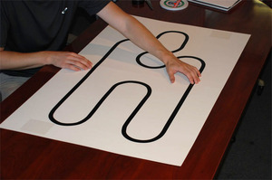
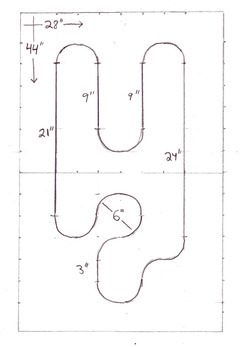 |
A sketch of the course that we will be building. |
|---|
Step 1: Plan your course.
Sketch out your course on a piece of paper. We recommend including precise dimensions so that you can make multiple copies of the course, publish the plan on your website, etc. You should take into account the dimensions of the posterboard sheets that you will use to build the course and the circular object that you will use to trace arcs.
The picture at right shows a plan for a line course on two 22"×28" posterboard sheets. Leaving borders of 4" and 5" on the long and short sides brings the usable area to 36"×18", which we divided into a grid with a 3" spacing. You can see faint marks around the edge of the sketch indicating the spacing of the grid. The 3" spacing nicely matches the 6"-diameter plastic lid that we will use to draw circles.
Step 2: Pencil the course onto the posterboard sheets.
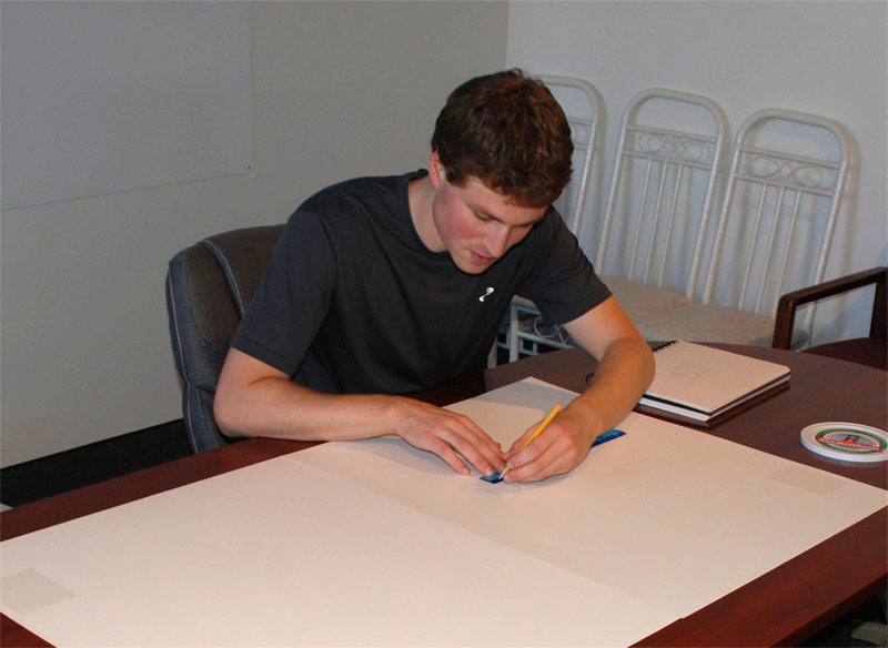 |
Draw straight lines with a pencil and straightedge. |
|---|
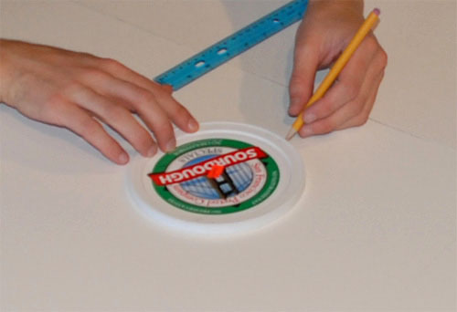 |
Drawing arcs and circles with a handy plastic lid. |
|---|
The next step is to transfer your sketch onto the posterboard. We started by carefully marking our 3" grid around the edge of the sheets with a ruler and a pencil, then measuring inward to mark key points on the path.
Since all of our straight segments are multiples of 3" long, and the arcs are 90°, 180°, or 270°, the beginning and end of every straight segment and arc is on a grid point. Centers of circles used to make arcs also fall on grid points.
Lightly pencil in the complete path of your course. Draw straight segments of the path against the ruler, and use your circular object to draw accurate circular arcs.
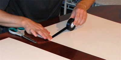
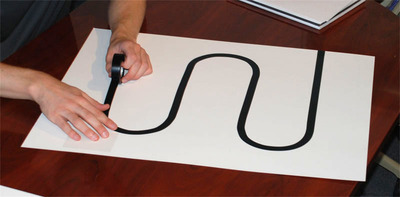
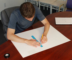
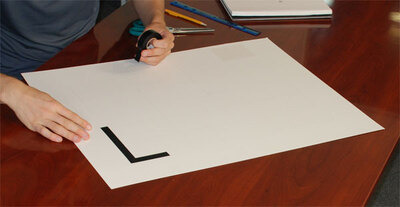
Step 3: Stretch the electrical tape along the pencil line of the first sheet of posterboard.
This is the step where it is important to be as neat as possible, so that your final course will look beautiful. The key is to always keep the electrical tape stretched out tightly in a direction tangent to the path, so that when you press it down onto the posterboard, it will make a consistent, clean, line.
 |
Stretch out the tape to make a straight line. |
|---|
 |
Press the tape down to the posterboard. |
|---|
When going around the curves, it is particularly important to stretch the tape tightly. To make sure you are stretching it in the right direction, visualize a line drawn from the point where the tape separates from the posterboard to the center of the circle that you are following. This line should always be at 90° to the direction that the tape is stretched. To avoid forming creases, make sure that you are stretching the outer edge of the tape to form the curve, instead of compressing the inner edge.
 |
Stretch the tape very tightly, following the penciled curve. |
|---|
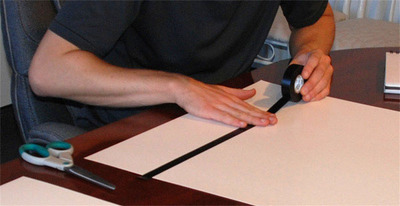
Keep following the curves and straight segments until you have traced out this half of the course. Electrical tape is forgiving: if you make a mistake, you can carefully pull it off of the posterboard and try again.
 |
Continue stretching the tape into the second straight segment. |
|---|
 |
Finish the rest of the line on this sheet in the same way. |
|---|
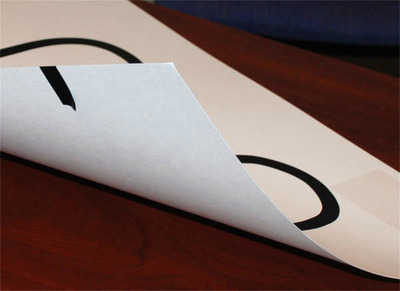
Step 4: Finish the ends.
Cut off the end of the tape. To make the line go cleanly to the end of the sheet, tuck the last inch or so under the posterboard:
 |
Tuck the tape under to make a smooth end. |
|---|
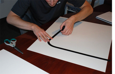
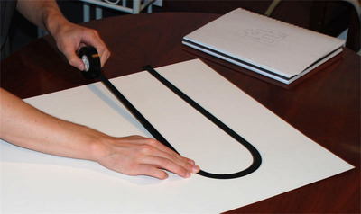
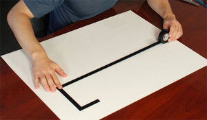
Step 5: Apply tape to the other sheet.
You should be able to create the line on the second sheet of posterboard in the same way as the first. This side of our course has a nice 270° curve that has now taken shape; look at how close the lines get before and after this turn. We are using 6" arcs; if we used smaller dimensions, the lines might be too close for a robot to safely follow.
 |
Construct the second half of the line course in the same way. |
|---|
Step 6: Assemble your course and put a robot on it.
You will probably find it necessary to connect the two halves of the course with masking tape or some kind of clips; otherwise, the sheets will gradually move apart as your robots zoom around the curves.
 |
Put the pieces together to make a finished course. |
|---|
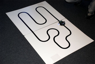 |
3pi on the line course, ready to race. |
|---|
Your course is now complete! It’s perfect for racing the 3pi robot or your own custom robot based on a QTR sensor array. Example line-following code for the 3pi is included with the Pololu AVR C/C++ Library and discussed in detail in Section 7.a of the Pololu 3pi Robot User’s Guide.
4. Building the Line Maze Course
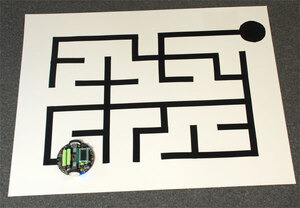
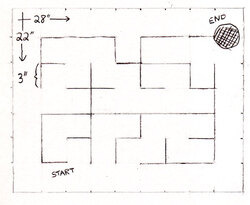 |
A sketch of the maze course. |
|---|
Step 1: Plan your maze.
The maze we will be building in this section is aligned on a 3" grid, so that parallel segments are never closer than 3". This grid is quite small, but it fits the 3pi robot well, and it allows an interesting maze to fit on a single sheet of posterboard. If you want to use a larger grid, you can combine multiple sheets together, just like we did with the line course. You can also use multiple sheets to make more complicated courses, and the sheets can even be rearranged to make a variety of different mazes. At Pololu, our favorite maze is an 8’×8’ course, using a 6" grid, made out of four 4’-square pieces of whiteboard material that can be rearranged to form many different combinations.
The course drawn at right has an important feature: it has no loops. This means that your robot can navigate through the entire course, starting from any point, by following a very simple “left hand on the wall” strategy, where it turns left, if possible, at every intersection. Looped mazes are more complicated, because this simple strategy will often cause the robot to get stuck in an infinite loop or to bypass an important section of the maze. For a robot to navigate a looped maze, it needs to be able to measure its current position accurately enough to determine when it has encountered a loop. This requires precision timing or some kind of wheel encoding, and it adds another level of complexity to the program. We recommend using no loops for your first maze.
For our course, we’ve also been careful to make the total length of the side-paths equal on the right and left sides of the shortest path through the maze. This means that a “left hand” and a “right hand” robot should take about the same amount of time to solve the maze.
Step 2: Pencil the course onto the posterboard sheet.
 |
Draw the grid lightly in pencil. |
|---|
Start by marking the edges of the posterboard with 3" tick marks, then using a long straightedge (such as another piece of posterboard) to lightly pencil in the grid. Then, with darker lines, highlight the segments that will become part of the maze.
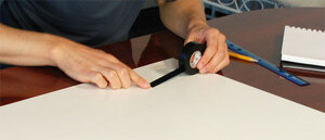
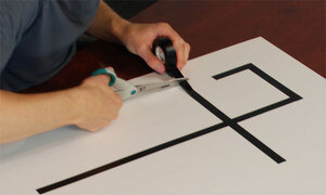
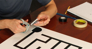
Step 3: Place electrical tape along each segment of the maze.
 |
Start with a cleanly-cut piece of tape for the first segment. |
|---|
Each line segment of the maze should be made with a cleanly-cut piece of electrical tape that stretches 3/8" past the grid point on either side, so that it will be aligned with the segments at right angles to it.
 |
Make the next segment with a separate piece of tape. |
|---|
Make each piece as long as possible, overlapping them at the corners and intersections. You’ll need to pay careful attention to the corners so that they come out as clean as possible. Any extra pieces of tape that stick out at incorrect angles could cause a robot to confuse, for example, corners with T-intersections. When debugging your code, you don’t want to worry about whether the robot was confused by the course or just badly programmed, so make it neat!
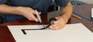 |
Cut the end of each segment as straight as possible. |
|---|
Cuts should be made at precise right angles. Don’t worry if you cut the tape too short; if you can’t stretch it to fit, you can carefully peel it off and try again with a new piece.
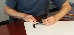
Here’s what the first corner of our maze looks like:
 |
 |
This long segment is made with a single piece of tape. |
|---|
We put a long straight segment in the middle of the maze. After learning the path, an advanced robot could take advantage of this, accelerating briefly to full speed, to finish the maze a fraction of a second faster than a robot with a simpler program. This will give you and your competitors a reason to keep improving your code!
Note that two pieces of tape can overlap to form a four-way crossing, without any ugly cuts at the intersection:
 |
This intersection is made with another piece, overlapping the previous one. |
|---|
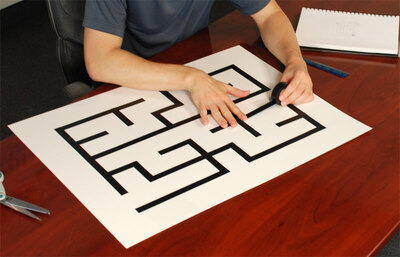
Keep putting down segments of tape until you have completely copied your design.
 |
Putting down the last line segment of the course. |
|---|
 |
The dot at the finish requires extra care. |
|---|
We use a 3" circle to signify the end of the maze. Since it is so different from the straight lines and corners in the rest of the course, the circle can actually be very difficult to detect. You’ll spend a significant amount of time making your program detect the ending reliably, so make sure that you also spend enough time to make the circle look nice. You could also use a 3" square block to make a simpler ending, but make sure that it doesn’t get too close to the nearby lines.
 |
A 3pi ready to run on the finished course. |
|---|
Your maze is now complete! It’s perfect for the 3pi robot or your own custom robot based on a QTR sensor array. For more information on how to actually program a maze-solving robot, please take a look at Section 8 of the 3pi user’s guide. You might also want to take a look at this maze-solving algorithm presentation (505k pdf) written by customer (and robotics professor) R. Vannoy.
Related products


Home | Forum | Blog | Support | Ordering Information | Lists | Distributors | BIG Order Form | About | Contact
© 2001–2026 Pololu Corporation
