Pololu Blog »
Paul's Wixel-based line following robot: Two Point Four
 |
Two Point Four was my entry in the LVBots 2015 line following competition, originally built for our 2013 contest but significantly rebuilt since then. I designed it to be simple, low-power, and lightweight, starting with its 2×AAA, 2.4 V nominal power supply, from which it gets its name.
When designing a robot, after batteries, the next thing to select is the motors, since they are so crucial to performance and constrain all the other parts. I wanted this robot to be a little faster than the 3pi, which uses 30:1 Micro Metal Gearmotors, so I expected to need a lower gear ratio, a higher-power motor, or both. Using the RPM values in the table at the top of our micro metal gearmotors category, I compared all such motors to the 3pi motors:
| Motor | Speed relative to 3pi motors |
|---|---|
| 5:1 HP | 14x |
| 10:1 HP | 7x |
| 30:1 HP | 2x |
| 10:1 MP | 5x |
| 30:1 MP | 1.6x |
| 5:1 LP | 6x |
| 10:1 LP | 3x |
 |
Paul’s line follower “Two Point Four”, showing DRV8835 motor driver. |
|---|
Since my voltage was about one-fourth of the 3pi’s boosted 9.75 V, I needed a motor rated more than four times faster. I selected the 10:1 MP Micro Metal Gearmotors, giving Two Point Four an expected advantage over the 3pi of about 25%. With that motor selected, I knew my current requirements would be only about 350 mA per channel at most, so the tiny DRV8835, which can do 1.2 A, would have no problem handling the load. Also, unlike many motor drivers, the DRV8835 has no minimum motor voltage requirement and works fine at 2.4 V.
I wanted the robot to be controlled by a Wixel, our wireless microcontroller module based on TI’s CC2511 chip, because of its easy USB programmability and 3.3 V operation (I did not use its wireless features). To power a 3.3 V system from 2×AAA batteries, it makes sense to use a 3.3 V boost regulator, for which I selected our four-pin U1V11F3. The smaller and cheaper U1V10F3, released after I built the robot, would probably have worked just as well. The final required component was a set of line sensors; all you really need for line following is a two-sensor array, and an easy way to get one is by using the snap-off section of our QTR-8A.
Here is a schematic showing all of these parts:
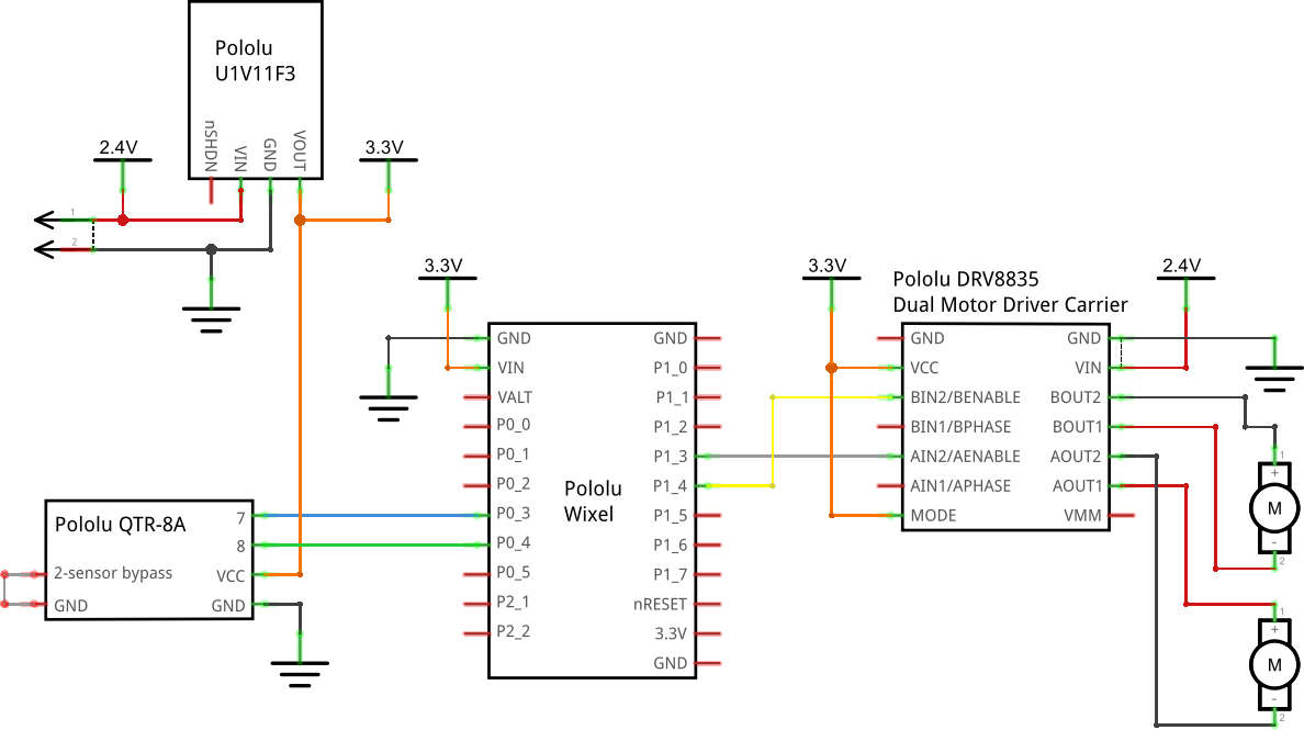 |
Note that the direction inputs of the motor driver are left unconnected. A line follower never needs to back up, so connecting them would have just added weight and complexity.
Rather than use a heavy breadboard, I made most of the connections directly from board to board with Premium Jumper Wires. For power distribution, I did use a 3×7 female header with rows of its pins soldered together, basically as a micro breadboard; I find that to be a handy trick for building compact, reconfigurable circuits. The diagram below shows how everything is wired up:
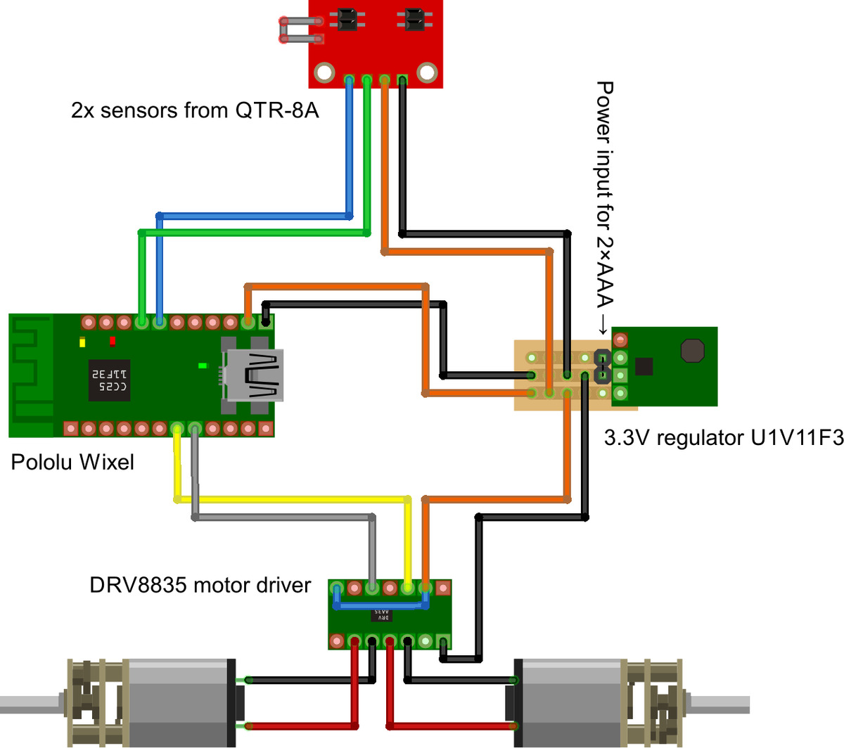 |
Note there are no buttons, power switch, or any kind of a user interface. I just plug in the battery connector and it starts running immediately. This means that sensor calibration values have to be hard-coded.
For a chassis, Two Point Four initially used a random laser-cut acrylic piece that I found in Ben’s office – actually part of a prototype Romo chassis. I used this version to place second in our 2013 line following contest; you can see some video of it in action at that link. But I rebuilt it to be smaller and faster for this contest, and as part of that I designed my own more minimal chassis, still out of laser-cut 1/8″ acrylic.
In the days leading up to the 2015 contest, while I was rebuilding the robot, our new 40mm wheels arrived, so I swapped my 32mm wheels for these to see if I could get an additional boost in performance:
 |
They did make the robot faster, but it also became noticeably less stable, which erased most of the difference, leaving me with only about a 3% improvement in actual time around the track. That 3% was not enough to beat Ben’s Mostly Red Racer, which took first place for the second time in a row this year. The other competition had also gotten a lot better since the last contest, and Two Point Four ended up around fourth place.
Want to use my design as a starting point for your own robot? My source repository on GitHub has all the code, chassis design files, and the Fritzing wiring diagrams.
Related products


-
New product: A-Star 32U4 Robot Controller with Raspberry Pi Bridge
- 7 August 2015I am excited to announce our new A-Star 32U4 Robot Controller LV with Raspberry Pi Bridge, a general-purpose robot controller based on Atmel’s...
-

Cable for Sharp GP2Y0A51SK0F analog distance sensors now available
- 28 August 2015We are now finally carrying a cable for the Sharp GP2Y0A51SK0F Analog Distance Sensor 2-15cm. The GP2Y0A51SK0F, our shortest-range analog distance...
2 comments


We noticed that you asked a similar question on a few of these line-follower blog posts. In order to keep the comments from getting too cluttered, we responded to your post here.
In the future, you might consider posting questions like these on our forum.
Brandon
Post a comment


Home | Forum | Blog | Support | Ordering Information | Lists | Distributors | BIG Order Form | About | Contact
© 2001–2026 Pololu Corporation
